

2005-2011 Mitsubishi Triton Service & Repair Manual
What's Included?
Fast Download Speeds
Online & Offline Access
Access PDF Contents & Bookmarks
Full Search Facility
Print one or all pages of your manual

00-1
GROUP 00
GENERAL
CONTENTS
GENERAL . . . . . . . . . . . . . . . . . . . . . . . . . . . . . . . . . . . . . . . . . . 00
GENERAL <ELECTRICAL> . . . . . . . . . . . . . . . . . . . . . . . . . . . . 00E

00-1
GROUP 00
GENERAL
CONTENTS
HOW TO USE THIS MANUAL . . . . . . 00-3
HOW TO USE TROUBLESHOOTING/
INSPECTION SERVICE POINTS. . . . 00-6
CONTENTS OF TROUBLESHOOTING . . . 00-6
DIAGNOSIS FUNCTION. . . . . . . . . . . . . . . 00-8
HOW TO USE THE INSPECTION PROCEDURES
. . . . . . . . . . . . . . . . . . . . . . . . . . . . . . . . . . . . . . 00-9
CONNECTOR MEASUREMENT SERVICE POINTS
. . . . . . . . . . . . . . . . . . . . . . . . . . . . . . . . . . . . . . 00-12
CONNECTOR INSPECTION SERVICE POINTS
. . . . . . . . . . . . . . . . . . . . . . . . . . . . . . . . . . . . . . 00-13
INSPECTION SERVICE POINTS FOR A BLOWN
FUSE. . . . . . . . . . . . . . . . . . . . . . . . . . . . . . 00-14
HOW TO COPE WITH INTERMITTENT
MALFUNCTIONS . . . . . . . . . . . . . . . . . . . . 00-14
HOW TO TREAT PAST TROUBLE . . . . . . 00-15
VEHICLE IDENTIFICATION . . . . . . . 00-15
MODELS . . . . . . . . . . . . . . . . . . . . . . . . . . . 00-15
VEHICLE IDENTIFICATION NUMBER (CHASSIS
NUMBER) . . . . . . . . . . . . . . . . . . . . . . . . . . 00-18
VEHICLE INFORMATION CODE PLATE. . 00-19
VEHICLE IDENTIFICATION NUMBER (VIN) PLATE
<VEHICLES FOR RHD> . . . . . . . . . . . . . . . 00-19
MANUFACTURER PLATE . . . . . . . . . . . . . 00-20
ENGINE MODEL STAMPING. . . . . . . . . . . 00-20
GENERAL DATA AND SPECIFICATIONS
. . . . . . . . . . . . . . . . . . . . . . . . . . . . . . . . . 00-21
GENERAL DATA AND SPECIFICATIONS
<VEHICLES FOR EUROPE> . . . . . . . . . . . 00-21
GENERAL DATA AND SPECIFICATIONS
<VEHICLES FOR RUSSIA (EASTERN EUROPE
COUNTRIES)> . . . . . . . . . . . . . . . . . . . . . . 00-32
GENERAL DATA AND SPECIFICATIONS
<VEHICLES FOR MOROCCO> . . . . . . . . . 00-35
PRECAUTIONS BEFORE SERVICE . 00-36
SERVICING COMMON RAIL ENGINE . . . . 00-36
CAUTIONS FOR AIR CONDITIONER STARITING
. . . . . . . . . . . . . . . . . . . . . . . . . . . . . . . . . . . . . . 00-36
SUPPLEMENTAL RESTRAINT SYSTEM (SRS)
. . . . . . . . . . . . . . . . . . . . . . . . . . . . . . . . . . . . . . 00-37
SERVICING ELECTRICAL SYSTEM . . . . . 00-37
IN ORDER TO PREVENT VEHICLES FROM FIRE
. . . . . . . . . . . . . . . . . . . . . . . . . . . . . . . . . . . . . . 00-37
MULTI USE TESTER (M.U.T.-III) SUB ASSEMBLY
. . . . . . . . . . . . . . . . . . . . . . . . . . . . . . . . . . . . . . 00-38
HOW TO PERFORM CHASSIS NUMBER (Chassis
No.) WRITING . . . . . . . . . . . . . . . . . . . . . . . 00-38
PRE-INSPECTION CONDITION . . . . . . . . . 00-42
ENGINE OILS . . . . . . . . . . . . . . . . . . . . . . . 00-42
WHAT THE COMMON RAIL ENGINE LEARNS
. . . . . . . . . . . . . . . . . . . . . . . . . . . . . . . . . . . . . . 00-43
INJECTOR IDENTIFICATION CODE REGISTRATION
PROCEDURE . . . . . . . . . . . . . . . . . . . . . . . 00-43
SMALL INJECTION QUANTITY LEARNING
PROCEDURE . . . . . . . . . . . . . . . . . . . . . . . 00-45
SUPPLY PUMP CORRECTION LEARNING
PROCEDURE . . . . . . . . . . . . . . . . . . . . . . . 00-45
INITIALISATION PROCEDURE FOR LEARNING
VALUE IN DIESEL PARTICULATE FILTER (DPF)
SYSTEM <Euro5> . . . . . . . . . . . . . . . . . . . . 00-46
BATTERY CURRENT SENSOR CALIBRATION
<Euro5> . . . . . . . . . . . . . . . . . . . . . . . . . . . . 00-46
HOW TO USE THE THROTTLE CONTROLLER
. . . . . . . . . . . . . . . . . . . . . . . . . . . . . . . . . . . . . . 00-47
APPLICATION OF ANTI-CORROSION AGENTS AND
UNDERCOATS . . . . . . . . . . . . . . . . . . . . . . 00-47
VEHICLE WASHING . . . . . . . . . . . . . . . . . . 00-48
PRECAUTIONS FOR INSTALLATION OF ON-
VEHICLE RADIO TRANSMISSION EQUIPMENT
. . . . . . . . . . . . . . . . . . . . . . . . . . . . . . . . . . . . . . 00-48
SUPPLEMENTAL RESTRAINT SYSTEM (SRS)
. . . . . . . . . . . . . . . . . . . . . . . . . . . . . . . . . 00-48

00-2
SRS SERVICE PRECAUTIONS . . . . 00-50 SUPPORT LOCATIONS FOR LIFTING AND
JACKING . . . . . . . . . . . . . . . . . . . . . . 00-54

HOW TO USE THIS MANUAL
GENERAL
00-3
HOW TO USE THIS MANUAL
M1001000103302
SCOPE OF MAINTENANCE, REPAIR AND
SERVICING EXPLANATIONS
This manual provides explanations, etc. concerning
procedures for the inspection, maintenance, repair
and servicing of the subject model. Note, however,
that for engine and transmission-related component
parts, this manual covers only on-vehicle inspec-
tions, adjustments, and the removal and installation
procedures for major components. For detailed infor-
mation concerning the inspection, checking, adjust-
ment, disassembly and reassembly of the engine,
transmission and major components after they have
been removed from the vehicle, please refer to sepa-
rate manuals covering the engine and the transmis-
sion.
ON-VEHICLE SERVICE
"On-vehicle Service" is procedures for performing
inspections and adjustments of particularly important
locations with regard to the construction and for
maintenance and servicing, but other inspection (for
looseness, play, cracking, damage, etc.) must also
be performed.
INSPECTION
Under this title are presented inspection and check-
ing procedures to be performed by using special
tools and measuring instruments and by feeling, but,
for actual maintenance and servicing procedures,
visual inspections should always be performed as
well.
DEFINITION OF TERMS
STANDARD VALUE
Indicates the value used as the standard for judging
the quality of a part or assembly on inspection or the
value to which the part or assembly is corrected and
adjusted. It is given by tolerance.
LIMIT
Shows the standard for judging the quality of a part
or assembly on inspection and means the maximum
or minimum value within which the part or assembly
must be kept functionally or in strength. It is a value
established outside the range of standard value.
REFERENCE VALUE
Indicates the adjustment value prior to starting the
work (presented in order to facilitate assembly and
adjustment procedures, and so they can be com-
pleted in a shorter time).
DANGER, WARNING, AND CAUTION
DANGER, WARNING, and CAUTION call special
attention to a necessary action or to an action that
must be avoided. The differences among DANGER,
WARNING, and CAUTION are as follows:
• If a DANGER is not followed, the result is severe
bodily harm or even death.
• If a WARNING is not followed, the result could be
bodily injury.
• If a CAUTION is not followed, the result could be
damage to the vehicle, vehicle components or
service equipment.
INDICATION OF TIGHTENING TORQUE
Tightening torques (units: N⋅m) are set to take into
account the central value and the allowable toler-
ance. The central value is the target value, and the
allowable tolerance provides the checking range for
tightening torques. If bolts and nuts are not provided
with tightening torques.
MODEL INDICATIONS
The following abbreviations are used in this manual
for identification of model types.
2500:Indicates an engine with the 2,477mL <4D56>
diesel engine.
2WD:Indicates the 2-wheel drive vehicles.
4WD:Indicates the 4-wheel drive vehicles.
A/C:Indicates the air conditioner.
A/T:Indicates the automatic transmission.
DOHC: Indicates an engine with the double over-
head camshaft.
M/T:Indicates the manual transmission.
HOW TO USE THIS MANUAL
GENERAL
00-4
EXPLANATION OF MANUAL CONTENTS
AC311238
N
Denotes tightening torque.
For bolts and nuts which do
not have a tightening torque
listed, refer to the "Standard
Parts tightening-torque Table"
Indicates the
group title.
Indicates the
section title.
Indicates the
group number.
Indicates the page number.
Indicates procedures to be performed be-
fore the work in that section is started, and
procedures to be performed after the work
in that section is finished.
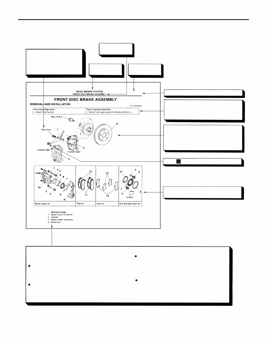
Component diagram
A diagram of the component parts is pro-
vided near the front of each section in order
to give the reader a better understanding of
the installed condition of component parts.
Mark denotes nonreusable part.
Repair kit or parts sets are shown.
(Only very frequently used parts are shown.)
Removal steps :
The part designation number corresponds to
the number in the illustration to indicate remov-
al steps.
Disassembly steps :
The part designation number corresponds to
the number in the illustration to indicate disas-
sembly steps.
Installation steps :
Specified in case installation is impossible in
reverse order of removal steps. Omitted if
installation is possible in reverse order of re-
moval steps.
Reassembly steps :
Specified in case installation is impossible in
reverse order of removal steps. Omitted if
reassembly is possible in reverse order of dis-
assembly steps.
Maintenance and servicing procedures
The numbers provided within the diagram indicate the
sequence for maintenance and servicing procedures.
AE
>>A<<
>>B<<
35A-19
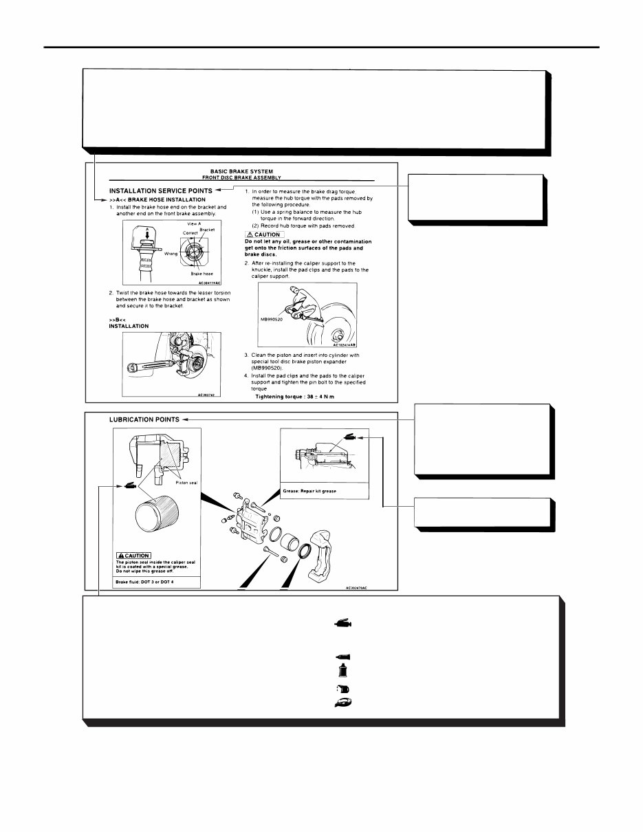
AC509265
Classifications of major maintenance / service points
When there are major points relative to maintenance and servicing procedures (such as essential maintenance
and service points, maintenance and service standard values, information regarding the use of special tools, etc.).
These are arranged together as major maintenance and service points and explained in detail.
<<A>> : Indicates that there are essential points for removal or disassembly.
>>A<< : Indicates that there are essential points for installation or reassembly.
Operating procedures,
cautions, etc. on removal,
installation, disassembly and
reassembly are described
The title of the page
(following the page on which
the diagram of component
parts is presented) indicating
the locations of lubrication and
sealing procedures.
Indicates (by symbols) where
lubrication is necessary.
AF
BRAKE CALIPER ASSEMBLY
35A-21
Symbols for lubrication, sealants and adhesives
Symbols are used to show the locations for lubrication
and for application of sealants and adhesives.
These symbols are included in the diagram of compo-
nent parts or on the page following the component
parts page. The symbols do not always have accomp-
anying text to support that symbol.
: Grease
(Multi-purpose grease unless there is a brand
or type specified)
: Sealant or adhesive
: Automatic transmission fluid, brake fluid, power
steering fluid or air conditioning compressor oil
: Engine oil or gear oil
: Adhesive tape or butyl rubber tape
HOW TO USE THIS MANUAL
GENERAL
00-5

HOW TO USE TROUBLESHOOTING/INSPECTION SERVICE POINTS
GENERAL
00-6
HOW TO USE TROUBLESHOOTING/INSPECTION SERVICE
POINTS
CONTENTS OF TROUBLESHOOTING
M1001013300794
CAUTION
During diagnosis, a diagnosis code associated
with other system may be set when the ignition
switch is turned on with connector(s) discon-
nected. On completion, confirm all systems for
diagnosis code(s). If diagnosis code(s) are set,
erase them all.
WARNING
Since the radiator fan rotates during CAN
bus line diagnostics, make sure that no one
is servicing the engine compartment before
diagnosing the CAN bus line. Since the CAN
communication stops when diagnosing the
CAN bus line, the ETACS-ECU detects the
time-out of the engine-ECU, and activates
the radiator fan to prevent overheating as
fail-safe.
Troubleshooting of electronic control systems for
which the M.U.T.-III can be used follows the basic
outline described below. Even in systems for which
the M.U.T.-III cannot be used, some of these sys-
tems still follow this outline.
1. STANDARD FLOW OF DIAGNOSIS TROUBLESHOOTING
Troubleshooting sections are based on the diagnostic flow as below. If the diagnostic flow is different from
that given below, or if additional explanation is required, the details of such differences or additions will also
be listed.
HOW TO USE TROUBLESHOOTING/INSPECTION SERVICE POINTS
GENERAL
00-7
Diagnosis method
AC501888
Gathering information
from the customer.
Check trouble symptom.
Reoccurs
Does not reoccur
CAN bus diagnosis chart* CAN bus diagnosis*
Read the diagnosis code. Read the diagnosis code.
After taking note of the
malfunction code, erase the
diagnosis code memory.
Recheck trouble symptom.
Read the diagnosis codes.
How to treat past
trouble*
Refer to the INSPECTION CHART
FOR DIAGNOSIS CODES
(Refer to applicable group).
How to treat past
trouble*
Refer to the INSPECTION CHART
FOR TROUBLE SYMPTOMS
(Refer to applicable group).
INTERMITTENT MALFUNCTIONS*
Diagnosis code
displayed.
(Current trouble)*
Diagnosis code
displayed.
(Current trouble)*
No diagnosis
code.
No diagnosis
code.
Diagnosis code
displayed.
(Past trouble)*
Diagnosis code
displayed.
(Past trouble)*
No diagnosis code
or communication
with M.U.T.-III not
possible
Diagnosis code
displayed.
OK
NG
2 1
3
3 3
3
4
4
5
• *
1
: For how to diagnose CAN bus lines, refer to GROUP 54C .
• *
2
: For the CAN bus diagnosis chart, refer to GROUP 54C .
• *
3
: When the M.U.T.-III detects a diagnosis code, its display informs users whether a mechanical problem
currently exists or whether it existed before. The message for the former state identifies it as a "Active"
and the message for the latter identifies it as a "Stored".
• *
4
: For how to treat past trouble, refer to P.00-15.
• *
5
: For how to cope with intermittent malfunctions, refer to P.00-14.
2. SYSTEM OPERATION AND SYMPTOM
VERIFICATION TESTS
If verification of the symptom(s) is difficult, proce-
dures for checking operation and verifying symptoms
are shown.
3. DIAGNOSIS FUNCTION
Details specific to individual systems are described.
4. DIAGNOSIS CODE CHART
Diagnosis codes and diagnostic items are shown.
5. DIAGNOSIS CODE PROCEDURES
Indicates the inspection procedures corresponding to
each diagnosis code (Refer to How to Use Inspection
Procedures P.00-9).
6. TROUBLE SYMPTOM CHART
If there are trouble symptoms even though the
M.U.T.-III does not find any diagnosis codes, Inspec-
tion procedures for each trouble symptom will be
found by means of this chart.
HOW TO USE TROUBLESHOOTING/INSPECTION SERVICE POINTS
GENERAL
00-8
7. SYMPTOM PROCEDURES
Indicates the inspection procedures corresponding to
each symptoms classified in the Symptom Chart
(Refer to How to Use Inspection Procedures P.00-9).
8. SERVICE DATA REFERENCE TABLE
Inspection items and normal judgment values have
been provided in this chart as reference information.
9. ACTUATOR TEST TABLE
The Actuator Test item numbers, inspection items,
and judgment values have been provided in this
chart as reference information.
10. CHECK AT ECU TERMINALS
Terminal numbers for the ECU connectors, inspec-
tion items, and judgment values have been provided
in this chart as reference information.
11. INSPECTION PROCEDURE BY USING
AN OSCILLOSCOPE
When there are inspection procedures using an
oscilloscope, these are described here.
DIAGNOSIS FUNCTION
M1001013400865
The diagnosis function retrieves diagnosis code and
service data by M.U.T.-III and enables the perform-
ance of the actuator test.
• DIAGNOSIS CODE
• Service data sent
• Actuator test
• Diagnosis deletion using M.U.T.-III
• Freeze frame data
• Status indication by diagnosis code
• ECU information display
NOTE: If a diagnosis code is set, the "status indica-
tion by diagnosis code" informs users whether a
mechanical problem currently exists (current trouble)
or whether it existed before but normal operation has
been restored (past trouble).
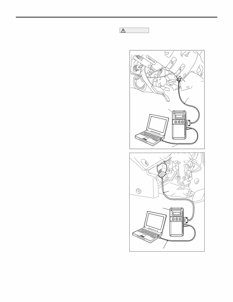
HOW TO READ DIAGNOSIS CODE
CAUTION
Before connecting or disconnecting the M.U.T.-
III, turn the ignition switch to the "LOCK" (OFF)
position.
AC509179 AB
Diagnosis
connector
MB991827
MB991824
MB991910
<LH drive vehicles>
AC501413AC
Diagnosis
connector
MB991827
MB991824
MB991910
<RH drive vehicles>
Connect the M.U.T.-III to the 16-pin diagnosis con-
nector, and read the diagnosis code.
NOTE: For details on how to use the M.U.T.-III, refer
to the "M.U.T.-III operation manual."
1. Ensure that the ignition switch is at the "LOCK"
(OFF) position.
2. Start up the personal computer.

HOW TO USE TROUBLESHOOTING/INSPECTION SERVICE POINTS
GENERAL
00-9
3. Connect special tool M.U.T.-III USB cable
MB991827 to V.C.I. (MB991824) and the personal
computer.
4. Connect special tool M.U.T.-III main harness A
(MB991910) to the V.C.I.
5. Connect the M.U.T.-III main harness A to the
diagnosis connector of the vehicle.
6. Turn the V.C.I. power switch to the "ON" position.
NOTE: When the V.C.I. is energized, the V.C.I.
indicator lamp will be illuminated in a green col-
our.
7. Start the M.U.T.-III system on the personal
computer and turn the ignition switch to the "ON"
position.
8. Read the diagnosis code.
NOTE: When storing the diagnosis code as refer-
ence information, the freeze frame data obtains the
data when the diagnosis code is confirmed, and then
stores the ECU status of that time. By analysing
each data using M.U.T.-III, troubleshooting can be
carried out efficiently.
9. Disconnecting the M.U.T.-III is the reverse of the
connecting sequence, making sure that the
ignition switch is at the "LOCK" (OFF) position.
ERASING DIAGNOSIS CODE
CAUTION
Before connecting or disconnecting the M.U.T.-
III, turn the ignition switch to the "LOCK" (OFF)
position.
Connect the M.U.T.-III to the diagnosis connector,
and erase the diagnosis code. The procedure is the
same as "How to Read Diagnosis Code ."
HOW TO USE THE INSPECTION
PROCEDURES
M1001013500345
The causes of many of the problems occurring in electric circuitry are generally the connectors, components,
the ECU, the wiring harnesses between connectors, in that order. These inspection procedures follow this
order. They first try to discover a problem with a connector or a defective component.
You're Reading a Preview
What's Included?
Fast Download Speeds
Online & Offline Access
Access PDF Contents & Bookmarks
Full Search Facility
Print one or all pages of your manual
$31.99
Viewed 95 Times Today


Secure transaction
What's Included?
Fast Download Speeds
Online & Offline Access
Access PDF Contents & Bookmarks
Full Search Facility
Print one or all pages of your manual
$31.99
Get instant access to the Complete Factory Service Repair Workshop Manual without any extra fees or expiry dates. This Professional Manual is suitable for both professional Mechanics and Technicians, as well as DIY enthusiasts. It covers all repairs, servicing, and troubleshooting procedures with detailed photos, diagrams, step-by-step instructions, and highly detailed exploded diagrams & pictures to ensure every job is completed correctly.
Print out a single page or the entire manual as per your choice. This Manual can be used on multiple computers without any limitations or trial periods, and it does not expire or require any renewal fees. It is fully compatible with all Windows & MAC Computers.


