00-2 SRS SERVICE PRECAUTIONS . . . . 00-50 SUPPORT LOCATIONS FOR LIFTING AND JACKING . . . . . . . . . . . . . . . . . . . . . . 00-54
HOW TO USE THIS MANUAL GENERAL 00-3 HOW TO USE THIS MANUAL M1001000103302 SCOPE OF MAINTENANCE, REPAIR AND SERVICING EXPLANATIONS This manual provides explanations, etc. concerning procedures for the inspection, maintenance, repair and servicing of the subject model. Note, however, that for engine and transmission-related component parts, this manual covers only on-vehicle inspec- tions, adjustments, and the removal and installation procedures for major components. For detailed infor- mation concerning the inspection, checking, adjust- ment, disassembly and reassembly of the engine, transmission and major components after they have been removed from the vehicle, please refer to sepa- rate manuals covering the engine and the transmis- sion. ON-VEHICLE SERVICE "On-vehicle Service" is procedures for performing inspections and adjustments of particularly important locations with regard to the construction and for maintenance and servicing, but other inspection (for looseness, play, cracking, damage, etc.) must also be performed. INSPECTION Under this title are presented inspection and check- ing procedures to be performed by using special tools and measuring instruments and by feeling, but, for actual maintenance and servicing procedures, visual inspections should always be performed as well. DEFINITION OF TERMS STANDARD VALUE Indicates the value used as the standard for judging the quality of a part or assembly on inspection or the value to which the part or assembly is corrected and adjusted. It is given by tolerance. LIMIT Shows the standard for judging the quality of a part or assembly on inspection and means the maximum or minimum value within which the part or assembly must be kept functionally or in strength. It is a value established outside the range of standard value. REFERENCE VALUE Indicates the adjustment value prior to starting the work (presented in order to facilitate assembly and adjustment procedures, and so they can be com- pleted in a shorter time). DANGER, WARNING, AND CAUTION DANGER, WARNING, and CAUTION call special attention to a necessary action or to an action that must be avoided. The differences among DANGER, WARNING, and CAUTION are as follows: • If a DANGER is not followed, the result is severe bodily harm or even death. • If a WARNING is not followed, the result could be bodily injury. • If a CAUTION is not followed, the result could be damage to the vehicle, vehicle components or service equipment. INDICATION OF TIGHTENING TORQUE Tightening torques (units: N⋅m) are set to take into account the central value and the allowable toler- ance. The central value is the target value, and the allowable tolerance provides the checking range for tightening torques. If bolts and nuts are not provided with tightening torques. MODEL INDICATIONS The following abbreviations are used in this manual for identification of model types. 2500:Indicates an engine with the 2,477mL <4D56> diesel engine. 2WD:Indicates the 2-wheel drive vehicles. 4WD:Indicates the 4-wheel drive vehicles. A/C:Indicates the air conditioner. A/T:Indicates the automatic transmission. DOHC: Indicates an engine with the double over- head camshaft. M/T:Indicates the manual transmission.
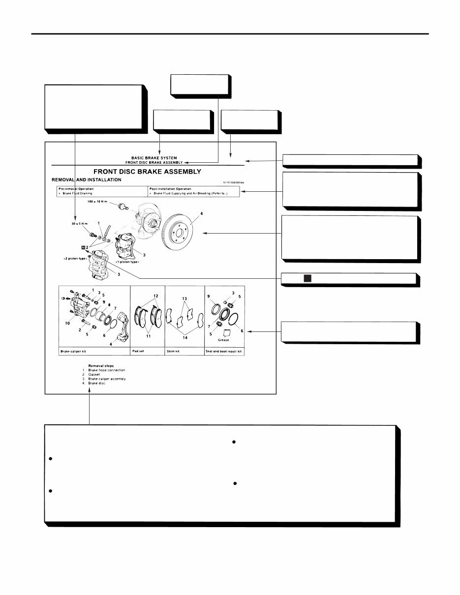
HOW TO USE THIS MANUAL GENERAL 00-4 EXPLANATION OF MANUAL CONTENTS AC311238 N Denotes tightening torque. For bolts and nuts which do not have a tightening torque listed, refer to the "Standard Parts tightening-torque Table" Indicates the group title. Indicates the section title. Indicates the group number. Indicates the page number. Indicates procedures to be performed be- fore the work in that section is started, and procedures to be performed after the work in that section is finished. Component diagram A diagram of the component parts is pro- vided near the front of each section in order to give the reader a better understanding of the installed condition of component parts. Mark denotes nonreusable part. Repair kit or parts sets are shown. (Only very frequently used parts are shown.) Removal steps : The part designation number corresponds to the number in the illustration to indicate remov- al steps. Disassembly steps : The part designation number corresponds to the number in the illustration to indicate disas- sembly steps. Installation steps : Specified in case installation is impossible in reverse order of removal steps. Omitted if installation is possible in reverse order of re- moval steps. Reassembly steps : Specified in case installation is impossible in reverse order of removal steps. Omitted if reassembly is possible in reverse order of dis- assembly steps. Maintenance and servicing procedures The numbers provided within the diagram indicate the sequence for maintenance and servicing procedures. AE >>A<< >>B<< 35A-19
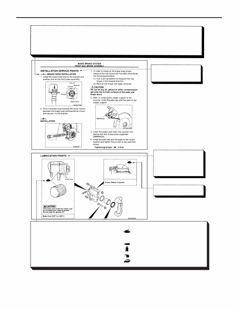
AC509265 Classifications of major maintenance / service points When there are major points relative to maintenance and servicing procedures (such as essential maintenance and service points, maintenance and service standard values, information regarding the use of special tools, etc.). These are arranged together as major maintenance and service points and explained in detail. <<A>> : Indicates that there are essential points for removal or disassembly. >>A<< : Indicates that there are essential points for installation or reassembly. Operating procedures, cautions, etc. on removal, installation, disassembly and reassembly are described The title of the page (following the page on which the diagram of component parts is presented) indicating the locations of lubrication and sealing procedures. Indicates (by symbols) where lubrication is necessary. AF BRAKE CALIPER ASSEMBLY 35A-21 Symbols for lubrication, sealants and adhesives Symbols are used to show the locations for lubrication and for application of sealants and adhesives. These symbols are included in the diagram of compo- nent parts or on the page following the component parts page. The symbols do not always have accomp- anying text to support that symbol. : Grease (Multi-purpose grease unless there is a brand or type specified) : Sealant or adhesive : Automatic transmission fluid, brake fluid, power steering fluid or air conditioning compressor oil : Engine oil or gear oil : Adhesive tape or butyl rubber tape HOW TO USE THIS MANUAL GENERAL 00-5
HOW TO USE TROUBLESHOOTING/INSPECTION SERVICE POINTS GENERAL 00-6 HOW TO USE TROUBLESHOOTING/INSPECTION SERVICE POINTS CONTENTS OF TROUBLESHOOTING M1001013300794 CAUTION During diagnosis, a diagnosis code associated with other system may be set when the ignition switch is turned on with connector(s) discon- nected. On completion, confirm all systems for diagnosis code(s). If diagnosis code(s) are set, erase them all. WARNING Since the radiator fan rotates during CAN bus line diagnostics, make sure that no one is servicing the engine compartment before diagnosing the CAN bus line. Since the CAN communication stops when diagnosing the CAN bus line, the ETACS-ECU detects the time-out of the engine-ECU, and activates the radiator fan to prevent overheating as fail-safe. Troubleshooting of electronic control systems for which the M.U.T.-III can be used follows the basic outline described below. Even in systems for which the M.U.T.-III cannot be used, some of these sys- tems still follow this outline. 1. STANDARD FLOW OF DIAGNOSIS TROUBLESHOOTING Troubleshooting sections are based on the diagnostic flow as below. If the diagnostic flow is different from that given below, or if additional explanation is required, the details of such differences or additions will also be listed.
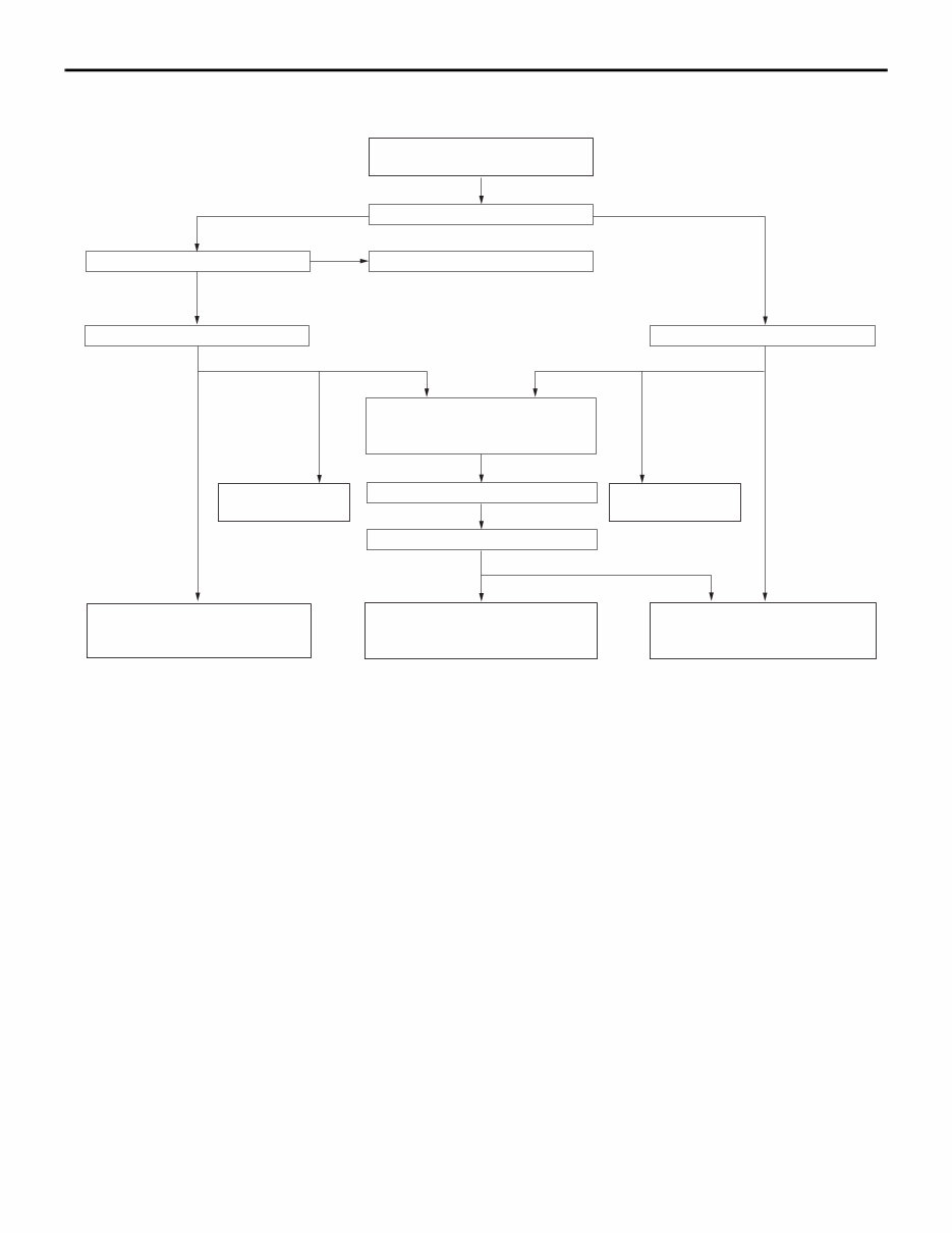
HOW TO USE TROUBLESHOOTING/INSPECTION SERVICE POINTS GENERAL 00-7 Diagnosis method AC501888 Gathering information from the customer. Check trouble symptom. Reoccurs Does not reoccur CAN bus diagnosis chart* CAN bus diagnosis* Read the diagnosis code. Read the diagnosis code. After taking note of the malfunction code, erase the diagnosis code memory. Recheck trouble symptom. Read the diagnosis codes. How to treat past trouble* Refer to the INSPECTION CHART FOR DIAGNOSIS CODES (Refer to applicable group). How to treat past trouble* Refer to the INSPECTION CHART FOR TROUBLE SYMPTOMS (Refer to applicable group). INTERMITTENT MALFUNCTIONS* Diagnosis code displayed. (Current trouble)* Diagnosis code displayed. (Current trouble)* No diagnosis code. No diagnosis code. Diagnosis code displayed. (Past trouble)* Diagnosis code displayed. (Past trouble)* No diagnosis code or communication with M.U.T.-III not possible Diagnosis code displayed. OK NG 2 1 3 3 3 3 4 4 5 • * 1 : For how to diagnose CAN bus lines, refer to GROUP 54C . • * 2 : For the CAN bus diagnosis chart, refer to GROUP 54C . • * 3 : When the M.U.T.-III detects a diagnosis code, its display informs users whether a mechanical problem currently exists or whether it existed before. The message for the former state identifies it as a "Active" and the message for the latter identifies it as a "Stored". • * 4 : For how to treat past trouble, refer to P.00-15. • * 5 : For how to cope with intermittent malfunctions, refer to P.00-14. 2. SYSTEM OPERATION AND SYMPTOM VERIFICATION TESTS If verification of the symptom(s) is difficult, proce- dures for checking operation and verifying symptoms are shown. 3. DIAGNOSIS FUNCTION Details specific to individual systems are described. 4. DIAGNOSIS CODE CHART Diagnosis codes and diagnostic items are shown. 5. DIAGNOSIS CODE PROCEDURES Indicates the inspection procedures corresponding to each diagnosis code (Refer to How to Use Inspection Procedures P.00-9). 6. TROUBLE SYMPTOM CHART If there are trouble symptoms even though the M.U.T.-III does not find any diagnosis codes, Inspec- tion procedures for each trouble symptom will be found by means of this chart.
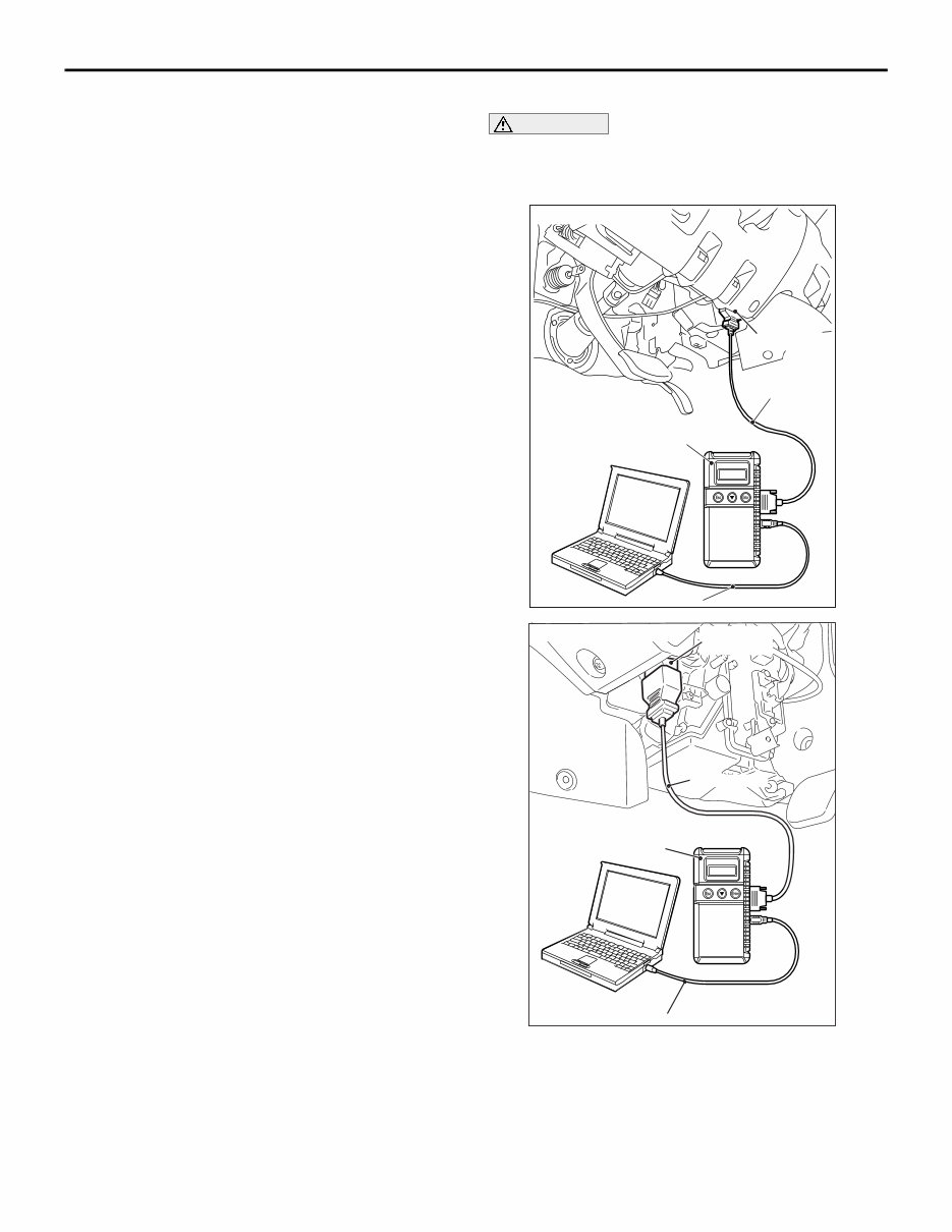
HOW TO USE TROUBLESHOOTING/INSPECTION SERVICE POINTS GENERAL 00-8 7. SYMPTOM PROCEDURES Indicates the inspection procedures corresponding to each symptoms classified in the Symptom Chart (Refer to How to Use Inspection Procedures P.00-9). 8. SERVICE DATA REFERENCE TABLE Inspection items and normal judgment values have been provided in this chart as reference information. 9. ACTUATOR TEST TABLE The Actuator Test item numbers, inspection items, and judgment values have been provided in this chart as reference information. 10. CHECK AT ECU TERMINALS Terminal numbers for the ECU connectors, inspec- tion items, and judgment values have been provided in this chart as reference information. 11. INSPECTION PROCEDURE BY USING AN OSCILLOSCOPE When there are inspection procedures using an oscilloscope, these are described here. DIAGNOSIS FUNCTION M1001013400865 The diagnosis function retrieves diagnosis code and service data by M.U.T.-III and enables the perform- ance of the actuator test. • DIAGNOSIS CODE • Service data sent • Actuator test • Diagnosis deletion using M.U.T.-III • Freeze frame data • Status indication by diagnosis code • ECU information display NOTE: If a diagnosis code is set, the "status indica- tion by diagnosis code" informs users whether a mechanical problem currently exists (current trouble) or whether it existed before but normal operation has been restored (past trouble). HOW TO READ DIAGNOSIS CODE CAUTION Before connecting or disconnecting the M.U.T.- III, turn the ignition switch to the "LOCK" (OFF) position. AC509179 AB Diagnosis connector MB991827 MB991824 MB991910 <LH drive vehicles> AC501413AC Diagnosis connector MB991827 MB991824 MB991910 <RH drive vehicles> Connect the M.U.T.-III to the 16-pin diagnosis con- nector, and read the diagnosis code. NOTE: For details on how to use the M.U.T.-III, refer to the "M.U.T.-III operation manual." 1. Ensure that the ignition switch is at the "LOCK" (OFF) position. 2. Start up the personal computer.
HOW TO USE TROUBLESHOOTING/INSPECTION SERVICE POINTS GENERAL 00-9 3. Connect special tool M.U.T.-III USB cable MB991827 to V.C.I. (MB991824) and the personal computer. 4. Connect special tool M.U.T.-III main harness A (MB991910) to the V.C.I. 5. Connect the M.U.T.-III main harness A to the diagnosis connector of the vehicle. 6. Turn the V.C.I. power switch to the "ON" position. NOTE: When the V.C.I. is energized, the V.C.I. indicator lamp will be illuminated in a green col- our. 7. Start the M.U.T.-III system on the personal computer and turn the ignition switch to the "ON" position. 8. Read the diagnosis code. NOTE: When storing the diagnosis code as refer- ence information, the freeze frame data obtains the data when the diagnosis code is confirmed, and then stores the ECU status of that time. By analysing each data using M.U.T.-III, troubleshooting can be carried out efficiently. 9. Disconnecting the M.U.T.-III is the reverse of the connecting sequence, making sure that the ignition switch is at the "LOCK" (OFF) position. ERASING DIAGNOSIS CODE CAUTION Before connecting or disconnecting the M.U.T.- III, turn the ignition switch to the "LOCK" (OFF) position. Connect the M.U.T.-III to the diagnosis connector, and erase the diagnosis code. The procedure is the same as "How to Read Diagnosis Code ." HOW TO USE THE INSPECTION PROCEDURES M1001013500345 The causes of many of the problems occurring in electric circuitry are generally the connectors, components, the ECU, the wiring harnesses between connectors, in that order. These inspection procedures follow this order. They first try to discover a problem with a connector or a defective component.
Get ready to tackle truck repairs with the 2005-2014 Mitsubishi Triton Service & Repair Manual. This comprehensive manual equips you with the manufacturer's recommended troubleshooting charts and replacement procedures, making it an invaluable resource for both professional mechanics and DIY enthusiasts.
Containing step-by-step instructions, clear images, and exploded-view illustrations, this manual covers every aspect of fixing problems and conducting regular maintenance on your truck. It's a convenient alternative to traditional bound manuals, allowing easy access to specific information without the hassle of flipping through numerous pages.
Whether you prefer digital access or a physical copy, this .pdf format manual is printable and compatible with various electronic devices, including PC & Mac computers, Android and Apple smartphones & tablets. It's a must-have for maintaining your truck's reliability and saving on repairs.
Format: .pdf
Printable: Yes
Language: English
Compatibility: Pretty much any electronic device, incl. PC & Mac computers, Android and Apple smartphones & tablets, etc.
Requirements: Adobe Reader (free)
Recently Viewed
5,521,897Happy Clients
2,594,462eManuals
1,120,453Trusted Sellers
15Years in Business
Price:
Actual Price:
2005-2014 Mitsubishi Triton Service & Repair Manual