1996-2007 Mitsubishi Triton Service & Repair Manual
What's Included?
Lifetime Access
Fast Download Speeds
Offline Viewing
Access Contents & Bookmarks
Full Search Facility
Print one or all pages of your manual
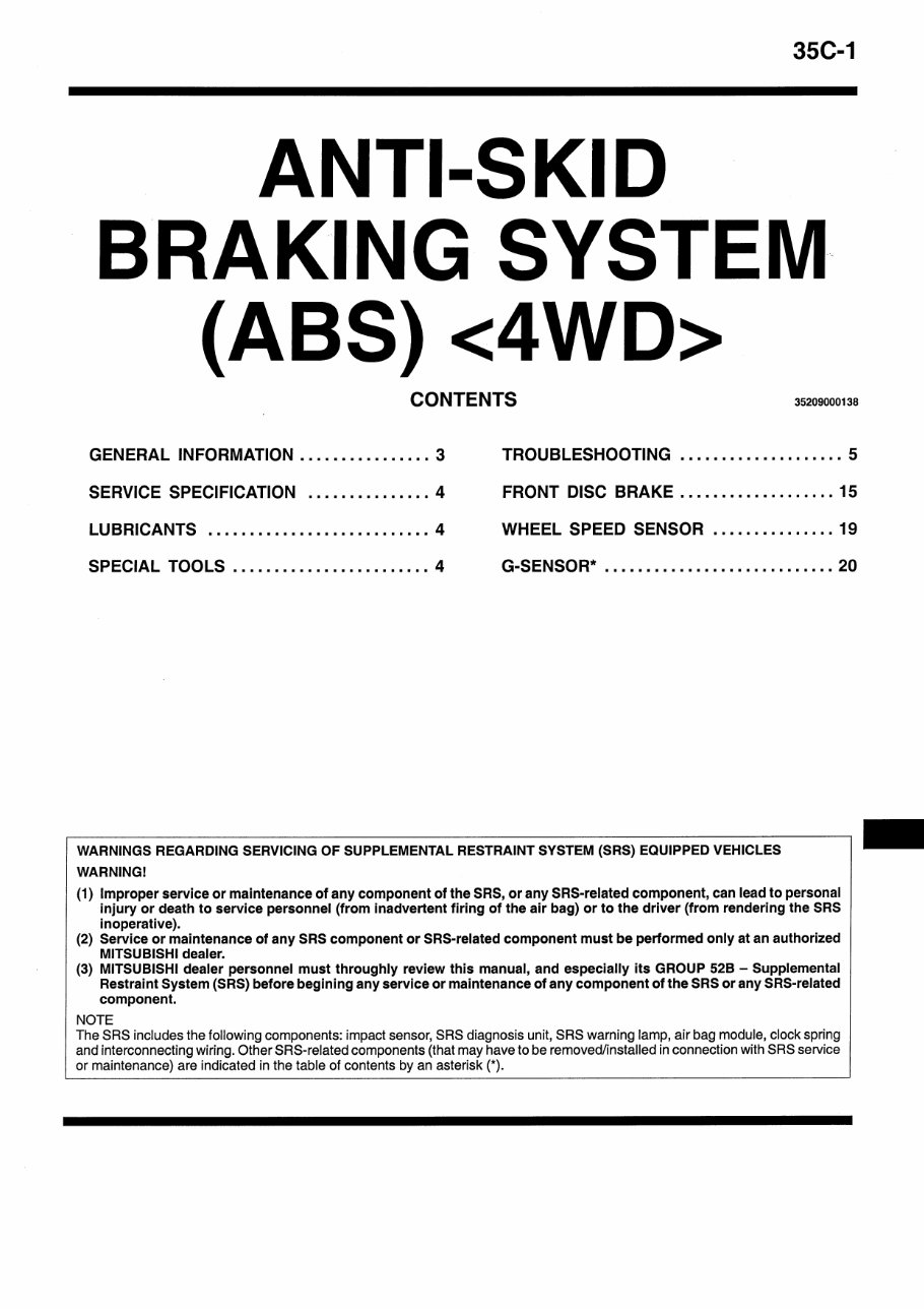
ANTI-SKID BRAKING SYSTEM (ABS) <4WD>
35C-2 For the items below, refer to GROUP 35A. SEALANTS ON-VEHICLE SERVICE Brake Pedal Check and Adjustment Stop Lamp Switch Inspection Brake Booster Operating Test Check Valve Operation Check Brake Booster Vacuum Switch Check Load Sensing Spring Length Check and Adjustment Load Sensing Proportioning Valve Function Test Front Disc Brake Rotor Check Brake Lining Thickness Check Brake Drum Inside Diameter Check Brake Lining and Brake Drum Connection Check BRAKE PEDAL LOAD SENSING PROPORTIONING VALVE REAR DRUM BRAKE For the items below, refer to GROUP 35B. ON-VEHICLE SERVICE Bleeding Disc Brake Pad Check and Replacement Wheel Speed Sensor Output Voltage Check Hydraulic Unit Check Solenoid Valve Check Motor Operation Check Motor Relay and Valve Relay Continuity Check Remedy for a Flat Battery MASTER CYLINDER AND BRAKE BOOSTER HYDRAULIC UNIT ABS-ECU
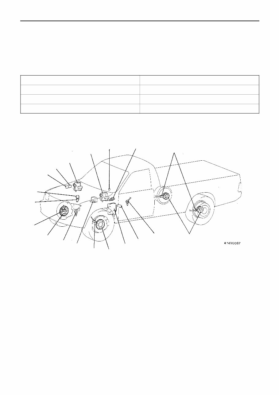
ABS <4WD> – General Information 35C-3 GENERAL INFORMATION 35200010130 The ABS consists of wheel speed sensors, stop lamp switch hydraulic unit and the ABS-ECU. If a problem occurs in the system, the malfunctioning system can be identified by means of the diagnosis function, and the trouble symptom memory will not be erased even if the ignition switch is turned to OFF. (However, it will be erased if the battery is disconnected.) In addition, reading of diagnosis codes and data list and actuator of testing are possible using the MUT-II. Items Specifications Speed sensor Magnet coil type Front rotor teeth 47 Rear rotor teeth 47 CONSTRUCTION DIAGRAM NOTE * 1 : For R.H. drive vehicles, those parts are installed at the right side. * 2 : Diesel-powered vehicles – L.H. drive vehicles. * 3 : Except diesel-powered vehicles – L.H. drive vehicles. 1 2 3* 1 4* 1 5 6 7* 1 8* 1 9* 2 10 11 12 13 14 9* 3 6 5 6 5 1. ABS valve relay 2. ABS motor relay 3. ABS warning lamp 4. Stop lamp switch 5. Rotor 6. Wheel speed sensor 7. ABS-ECU 8. Diagnosis connector 9. Hydraulic unit 10. G-sensor 11. 4WD position detection switch 12. Free wheel engage switch 13. Rear differential lock-ECU 14. 4WD indicator-ECU
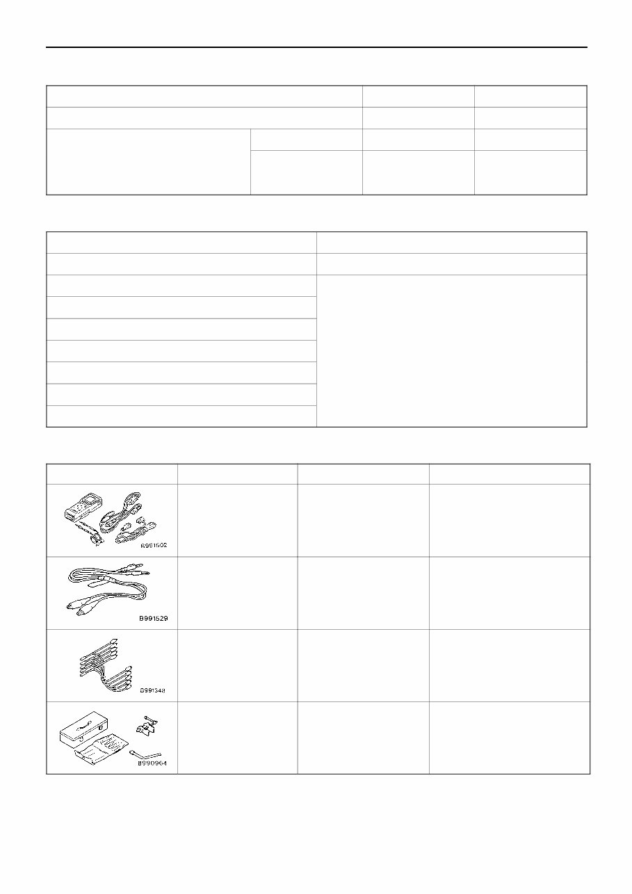
ABS <4WD> – Service Specification/Lubricants/Special Tools 35C-4 SERVICE SPECIFICATION 35200030143 Items Standard value Limit Front disc brake pad thickness mm 10 2.0 G-sensor output voltage V When installed 2.4 – 2.6 – When removed with arrow mark facing down 3.4 – 3.6 – LUBRICANTS 35200040030 Items Specified lubricant Brake fluid DOT3 or DOT4 Brake piston seal Repair kit grease Guide pin boot inner surfaces Lock pin boot inner surfaces Piston boot mounting grooves Brake piston boot inner surfaces Lock pin bush inner surfaces Piston cup surface SPECIAL TOOLS 35200060142 Tool Number Name Use MB991502 MUT-II sub assembly For checking of ABS (Diagnosis code display when using the MUT-II) MB991529 ABS check harness For checking of ABS (Diagnosis code display when using the ABS warning lamp) MB991348 Test harness set For checking of G-sensor MB990964 MB990520 Brake tool set Pushing-in of the brake piston
ABS <4WD> – Troubleshooting 35C-5 TROUBLESHOOTING 35101110143 STANDARD FLOW OF DIAGNOSTIC TROUBLESHOOTING Refer to GROUP 00 – How to Use Troubleshooting/Inspection Service Points. NOTES WITH REGARD TO DIAGNOSIS The phenomena listed in the following table are not abnormal. Phenomenon Explanation of phenomenon System check sound When starting the engine, a thudding sound can sometimes be heard coming from inside the engine compartment, but this is because the system operation check is being performed, and is not an abnormality. ABS operation sound 1. Sound of the motor inside the ABS hydraulic unit operation. (whine) 2. Sound is the generated along with vibration of the brake pedal. (scraping) 3. When ABS operates, sound is generated from the vehicle chassis due to repeated brake application and release. (Thump: suspension; squeak: tyres) ABS operation (Long braking distance) For road surfaces such as snow-covered roads and gravel roads, the braking distance for vehicles with ABS can sometimes be longer than that for other vehicles. Accordingly, advise the customer to drive safely on such roads by lowering the vehicle speed and not being too overconfident. Shock during system operation check Shock may be felt when the brake pedal is depressed slightly at a low driving speed. This occurs due to ABS operation check (check at a vehicle speed of 8 km/h after starting), and does not indicate any malfunction. Diagnosis detection condition can vary depending on the diagnosis code. Make sure that checking requirements listed in the “Comment” are satisfied when checking the trouble symptom again. DIAGNOSIS FUNCTION 35201120108 DIAGNOSIS CODES CHECK Read a diagnosis code by the MUT-II or ABS warning lamp. (Refer to GROUP 00 – How to Use Troubleshooting/Inspection Service Points.) ERASING DIAGNOSIS CODES Refer to GROUP 00 – How to Use Troubleshooting/Inspection Service Points.
ABS <4WD> – Troubleshooting 35C-6 INSPECTION CHART FOR DIAGNOSIS CODES 35201130163 Inspect according to the inspection chart that is appropriate for the malfunction code. Diagnosis code No. Inspection item Diagnosis content Reference page 11 Front right wheel speed sensor Open or short circuit Refer to GROUP 35B – Troubleshooting. 12 Front left wheel speed sensor 13 Rear right wheel speed sensor 14 Rear left wheel speed sensor 15 Wheel speed sensor Abnormal output signal Refer to GROUP 35B – Troubleshooting. 16 Power supply system Refer to GROUP 35B – Troubleshooting. 21 Front right wheel speed sensor Abnormal Refer to GROUP 35B – Troubleshooting. 22 Front left wheel speed sensor 23 Rear right wheel speed sensor 24 Rear left wheel speed sensor 25 Free wheel engage switch 35C-7 26 4WD position detection switch 35C-8 27 Rear differential lock detection switch 35C-9 32 G-sensor system 35C-10 33 Stop lamp switch system Refer to GROUP 35B – Troubleshooting. 41 Front right solenoid valve Refer to GROUP 35B – Troubleshooting. 42 Front left solenoid valve 43 Rear solenoid valve 51 Valve relay Refer to GROUP 35B – Troubleshooting. 53 Motor relay, motor Refer to GROUP 35B – Troubleshooting. 63 ABS-ECU Refer to GROUP 35B – ABS-ECU. (Replace the ABS-ECU ) 64 (Re lace the ABS-ECU.)
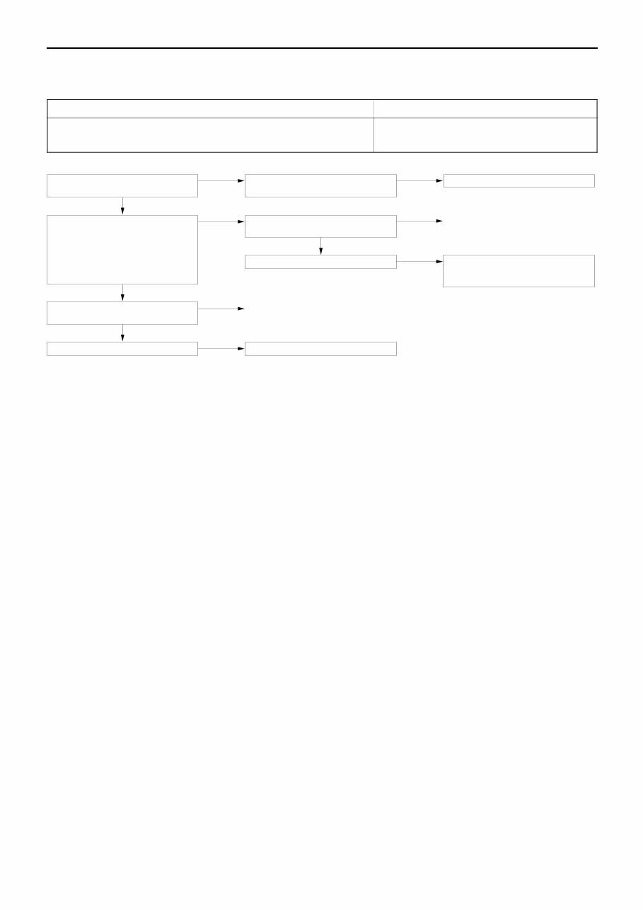
ABS <4WD> – Troubleshooting 35C-7 INSPECTION PROCEDURE CLASSIFIED BY DIAGNOSIS CODES For diagnosis code numbers other than those listed below, refer to GROUP 35B – Troubleshooting. Code No. 25 Free wheel engage switch Probable cause ABS-ECU determines that an open circuit exists in the free wheel engage switch system. D Malfunction of wiring harness or connector D Malfunction of 4WD indicator-ECU D Malfunction of ABS-ECU Does the 4WD indicator lamp operate normally? No 4WD indicator-ECU check. (Refer to GROUP 22 – 4WD indicator-ECU.) NG Replace the 4WD indicator-ECU. Yes Measure at ABS-ECU connector C-64. D Disconnect the connector and measure at the harness side. D Ignition switch ON D Voltage between 45 and body earth OK: System voltage <when in 2WD> or 0 V <when in 4WD> NG Check the following connectors. C-64 and A-02 NG Repair OK Check trouble symptom. NG Check the harness between free wheel engage switch and the ABS-ECU, and repair if necessary. OK Check the following connector. C-64 NG Repair OK Check trouble symptom. NG Replace the ABS-ECU.
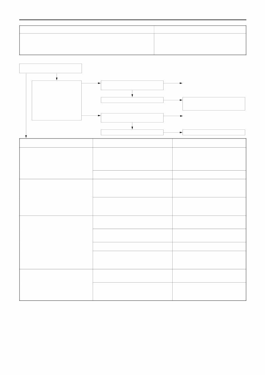
ABS <4WD> – Troubleshooting 35C-8 Code No. 26 4WD position detection switch Probable cause This code is output at the following times: ABS-ECU determines that an open circuit exists in the 4WD detection switch system. The free wheel engage switch is off and the 4WD detection switch is on at a vehicle speed of 15km/h or more for 5 seconds or more. D Malfunction of wiring harness or connector D Malfunction of free wheel engage switch D Malfunction of 4WD indicator-ECU D Malfunction of 4WD position detection switch D Malfunction of ABS-ECU No OK Check trouble symptom. NG Check the harnesses between 4WD position detection switch and the ABS- ECU, and repair if necessary. OK Check the following connector. C-64 NG Repair OK Check trouble symptom. NG Replace the ABS-ECU. Yes Measure at ABS-ECU connec- tor C-64. D Disconnect the connector and measure at the harness side. D Ignition switch ON D Transfer lever:2H D Voltage between 35 and body earth OK: System voltage NG Check the following connector. C-64 NG Repair Does the 4WD indicator lamp operate normally? Trouble symptom Main cause Remedy Even when the transfer shift lever is in the ”4H” position, the 4WD front wheel indicator lamp does not illuminate. Broken harness wire between the 4WD indicator-ECU and the free-wheel engage switch, or broken earth wire from the free wheel engage switch Repair the harness. Free wheel engage switch is defective. Replace the switch. Even when the transfer shift lever is in the ”4H” position, the free wheel differential indicator lamp does not illuminate Broken harness wire between the 4WD indicator-ECU and the 4WD position detection switch Repair the harness. illuminate. Broken wire in the 4WD indicator-ECU circuit 4WD indicator-ECU inspection (Re- fer to GROUP 22 – 4WD indicator- ECU.) Free wheel differential indicator lamp illuminates regardless of the position of the transfer shift lever Short in the harness wire in the 4WD position detection switch circuit Repair the harness. position of the transfer shift lever. 4WD position detection switch is defective. Replace the switch. Short in the ABS-ECU circuit Replace the ABS-ECU. Short in the 4WD indicator-ECU circuit 4WD indicator-ECU inspection (Re- fer to GROUP 22 – 4WD indicator- ECU.) No indicator is illuminated Power circuit in the 4WD indicator-ECU is defective. Repair the harness. 4WD indicator-ECU is defective. 4WD indicator-ECU inspection (Re- fer to GROUP 22 – 4WD indicator- ECU.) NOTE When checking a short in the ABS-ECU circuit, remove the ABS-ECU connector and check if the 4WD indicator returns to normal. If it returns to normal, the ABS-ECU is defective. Furthermore, if the ABS-ECU is normal, then the 4WD indicator-ECU will be defective.
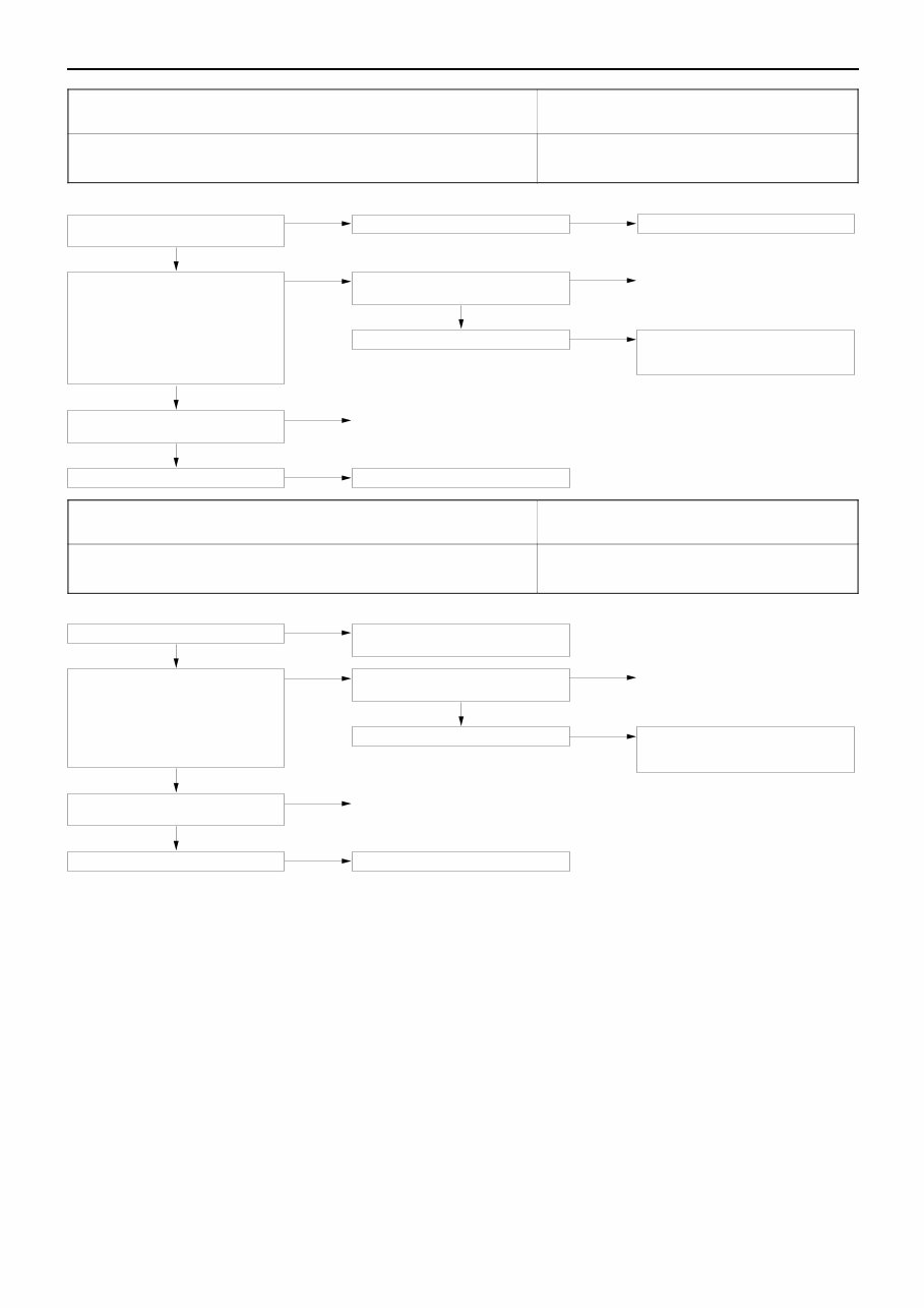
ABS <4WD> – Troubleshooting 35C-9 Code No. 27 Rear differential lock detection switch <Vehicles with rear differential lock> Probable cause The ABS-ECU determines that an open circuit occurs in rear differential detection switch system. D Malfunction of wiring harness or connector D Malfunction of rear differential lock-ECU D Malfunction of ABS-ECU Does the 4WD indicator lamp (rear dif- ferential lamp) operate normally? No Rear differential lock-ECU check. NG Replace the rear differential lock-ECU. Yes Measure at the ABS-ECU connector C-64. D Disconnect the connector and measure at the harness side. D Ignition switch: ON D Rear differential lock switch: OFF D Voltage between 46 and body earth OK: System voltage NG Check the following connectors. C-88, C-86, C-02 and C-64 NG Repair OK Check trouble symptom. NG Check the harness between rear differ- ential detection switch and the ABS- ECU, and repair if necessary. OK Check the following connector. C-64 NG Repair OK Check trouble symptoms. NG Replace the ABS-ECU. Code No. 27 Rear differential lock detection switch <Vehicles without rear differential lock> Probable cause For vehicles without rear differential lock, battery positive voltage is applied to the ABS-ECU terminal No. 46. This code is output when this line is interrupted. D Malfunction of wiring harness or connector D Malfunction of ABS-ECU Is the fuse No. 7 normal? No Replace the fuse after eliminating the cause of the blowout. Yes Measure at the ABS-ECU connector C-64. D Disconnect the connector and measure at the harness side. D Ignition switch ON D Voltage between 46 and body earth OK: System voltage NG Check the following connectors. C-88, C-86, C-02 and C-64 NG Repair OK Check trouble symptoms. NG Check the harness between fuse No. 7 inside the junction block and the ABS- ECU, and repair if necessary. OK Check the following connector. C-64 NG Repair OK Check trouble symptoms. NG Replace the ABS-ECU.
These comprehensive manuals are essential resources for anyone working with the third generation Mitsubishi L200 Triton (1996-2007), also known as Mitsubishi Storm, Mitsubishi Strada, or Mitsubishi Warrior. Whether you are a professional mechanic or a DIY enthusiast, these manuals provide over 300MB of workshop service information, supplements, and service bulletins. They also include full detail electrical wiring diagrams in a true type clear format, not a scanned version.
It's important to note that the manual for 2006-2007 is only compatible with Internet Explorer 6 & 5, and not with IE 7.
The manual CD covers a wide range of topics, including general information, engine specifications, lubrication, fuel systems, cooling systems, intake and exhaust systems, engine electrical systems, emission control, clutch, manual and automatic transmissions, axles, wheels, tires, suspension, brakes, steering, body, interior, supplemental restraint system (SRS), chassis electrical, and heating, air conditioning, and ventilation systems.
Recently Viewed
5,521,897Happy Clients
2,594,462eManuals
1,120,453Trusted Sellers
15Years in Business
Price:
Actual Price:
1996-2007 Mitsubishi Triton Service & Repair Manual