

1997-2002 Mitsubishi L200 MK Triton 2WD-4WD Ute Service & Repair Manual
What's Included?
Fast Download Speeds
Offline Viewing
Access Contents & Bookmarks
Full Search Facility
Print one or all pages of your manual
GENERAL
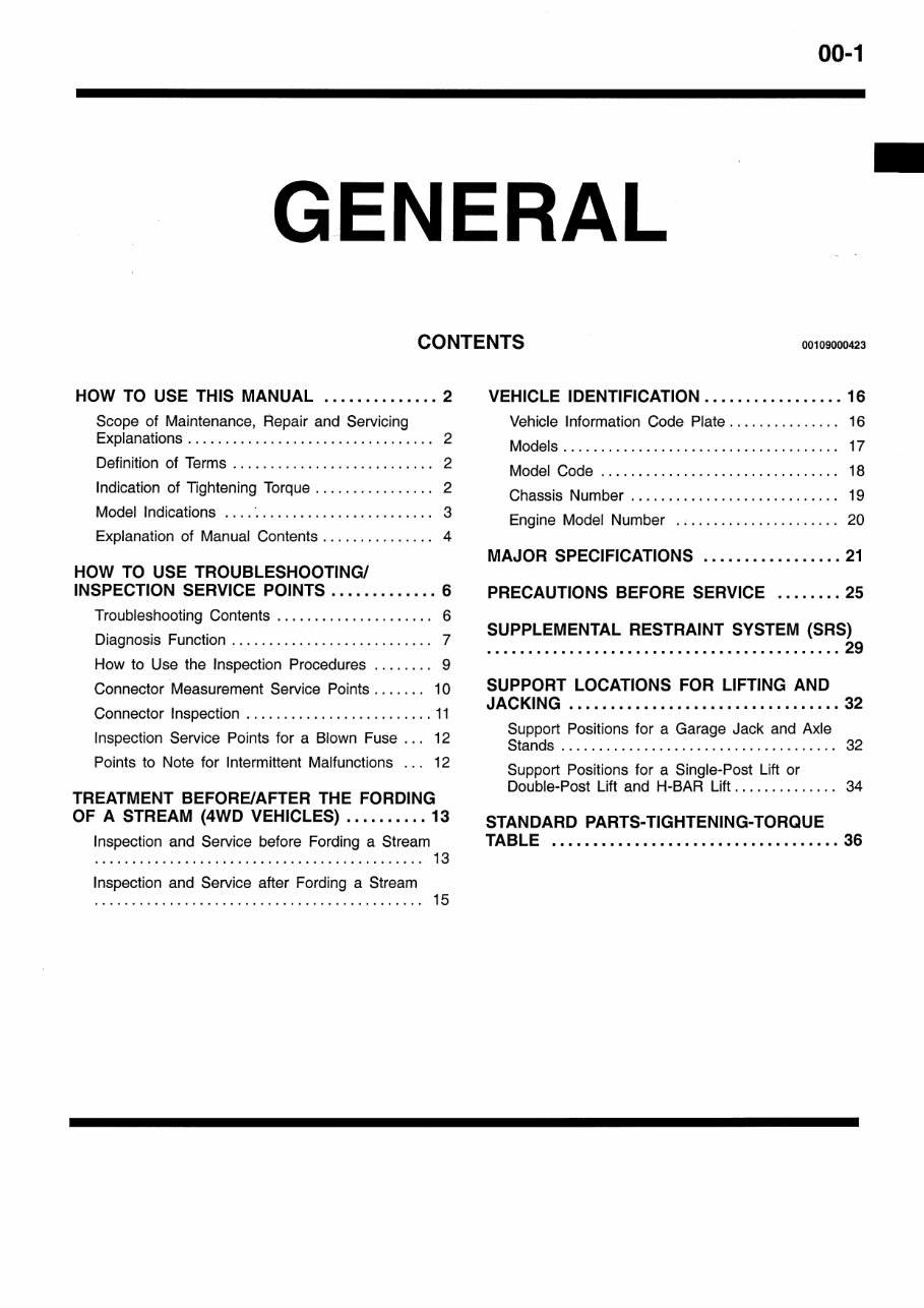

GENERAL – How to Use This Manual 00-2
HOW TO USE THIS MANUAL 00100010210
SCOPE OF MAINTENANCE, REPAIR
AND SERVICING EXPLANATIONS
This manual provides explanations, etc. concerning
procedures for the inspection, maintenance, repair
and servicing of the subject model. Note, however,
that for engine and transmission-related component
parts, this manual covers only on-vehicle
inspections, adjustments, and the removal and
installation procedures for major components.
For detailed information concerning the inspection,
checking, adjustment, disassembly and reassembly
of the engine, transmission and major components
after they have been removed from the vehicle,
please refer to separate manuals covering the
engine and the transmission.
ON-VEHICLE SERVICE
“On-vehicle Service” is procedures for performing
inspections and adjustments of particularly
important locations with regard to the construction
and for maintenance and servicing, but other
inspection (for looseness, play, cracking, damage,
etc.) must also be performed.
INSPECTION
Under this title are presented inspection and
checking procedures to be performed by using
special tools and measuring instruments and by
feeling, but, for actual maintenance and servicing
procedures, visual inspections should always be
performed as well.
DEFINITION OF TERMS
STANDARD VALUE
Indicates the value used as the standard for judging
the quality of a part or assembly on inspection
or the value to which the part or assembly is
corrected and adjusted. It is given by tolerance.
LIMIT
Shows the standard for judging the quality of a
part or assembly on inspection and means the
maximum or minimum value within which the part
or assembly must be kept functionally or in strength.
It is a value established outside the range of
standard value.
REFERENCE VALUE
Indicates the adjustment value prior to starting the
work (presented in order to facilitate assembly and
adjustment procedures, and so they can be
completed in a shorter time).
CAUTION
Indicates the presentation of information particularly
vital to the worker during the performance of
maintenance and servicing procedures in order to
avoid the possibility of injury to the worker, or
damage to component parts, or a reduction of
component or vehicle function or performance, etc.
INDICATION OF TIGHTENING TORQUE
The tightening torque shown in this manual is a
basic value with a tolerance of ±10% except the
following cases when the upper and lower limits
of tightening torque are given.
(1) The tolerance of the basic value is within ±10%.
(2) Special bolts or the like are in use.
(3) Special tightening methods are used.

GENERAL – How to Use This Manual 00-3
MODEL INDICATIONS
The following abbreviations are used in this manual for classification of model types.
M/T: Indicates the manual transmission, or models equipped with the manual transmission.
A/T: Indicates the automatic transmission, or models equipped with the automatic transmission.
SOHC: Indicates an engine with the single overhead camshaft, or a model equipped with such
an engine.
MPI: Indicates the multi-point injection, or engines equipped with the multi-point injection.
DIESEL: Indicates a diesel engine, or models equipped with such an engine.
2WD: Indicates the rear wheel-drive vehicles.
4WD: Indicates the 4 wheel-drive vehicles.
GENERAL – How to Use This Manual 00-4
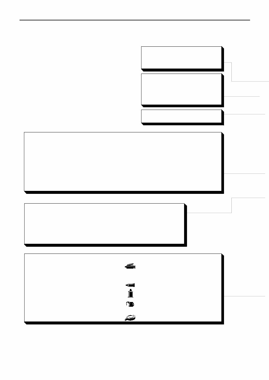
EXPLANATION OF MANUAL CONTENTS
Indicates procedures to be performed
before the work in that section is started,
and procedures to be performed after
the work in that section is finished.
Indicates (by symbols) where lubrica-
tion is necessary.
Maintenance and Servicing Procedures
The numbers provided within the diagram indi-
cate the sequence for maintenance and servic-
ing procedures.
D Removal steps:
The part designation number corresponds
to the number in the illustration to indicate
removal steps.
D Disassembly steps:
The part designation number corresponds
to the number in the illustration to indicate
disassembly steps.
D Installation steps:
Specified in case installation is impossible
in reverse order of removal steps. Omitted
if installation is possible in reverse order of
removal steps.
D Reassembly steps:
Specified in case reassembly is impossible
in reverse order of disassembly steps.
Omitted if reassemby is possible in reverse
order of disassembly steps.
Classifications of Major Maintenance/Service Points
When there are major points relative to maintenance and servicing procedures
(such as essential maintenance and service points, maintenance and service stan-
dard values, information regarding the use of special tools, etc.), these are ar-
ranged together as major maintenance and service points and explained in detail.
AA" : Indicates that there are essential points for removal or disassembly.
"AA : Indicates that there are essential points for installation or reassembly.
Symbols for Lubrication, Sealants and Adhesives
Information concerning the locations for lubrica-
tion and for application of sealants and adhe-
sives is provided, by using symbols, in the dia-
gram of component parts or on the page follow-
ing the component parts page, and explained.
: Grease
(multipurpose grease unless there is
a brand or type specified)
: Sealant or adhesive
: Brake fluid or automatic transmission fluid
: Engine oil, gear oil or air conditioner
compressor oil
: Adhesive tape or butyl rubber tape
Component Diagram
A diagram of the component parts is
provided near the front of each section
in order to give a reader a better under-
standing of the installed condition of
component parts.
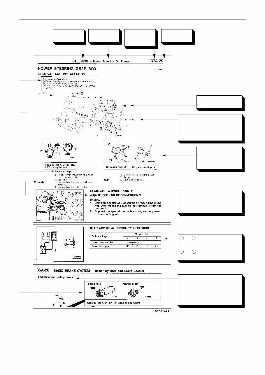
GENERAL – How to Use This Manual 00-5
Denotes tightening torque.
For bolts and nuts which do not
have a tightening torque listed,
refer to the “Standard Parts-
tightening-torque Table”.
indicates that there is
a continuity between the termi-
nals.
indicates terminals to
which battery voltage is applied.
Indicates the
section title.
Indicates the
group num-
ber.
Indicates the
page number.
Indicates the
group title.
Denotes non-reus-
able part.
Repair kit or set parts
are shown. (Only very
frequently used parts
are shown.)
Operating procedures, cau-
tions, etc. on removal, installa-
tion, disassembly and reas-
sembly are described.
The title of the page (following
the page on which the diagram
of component parts is pres-
ented) indicating the locations of
lubrication and sealing proce-
dures.
GENERAL – How to Use Troubleshooting/Inspection Service Points 00-6
HOW TO USE TROUBLESHOOTING/INSPECTION SERVICE
POINTS 00100020091
Troubleshooting of electronic control systems for which the MUT-II can be used follows the basic outline
described below. Furthermore, even in systems for which the MUT-II cannot be used, part of these systems
still follow this outline.
TROUBLESHOOTING CONTENTS
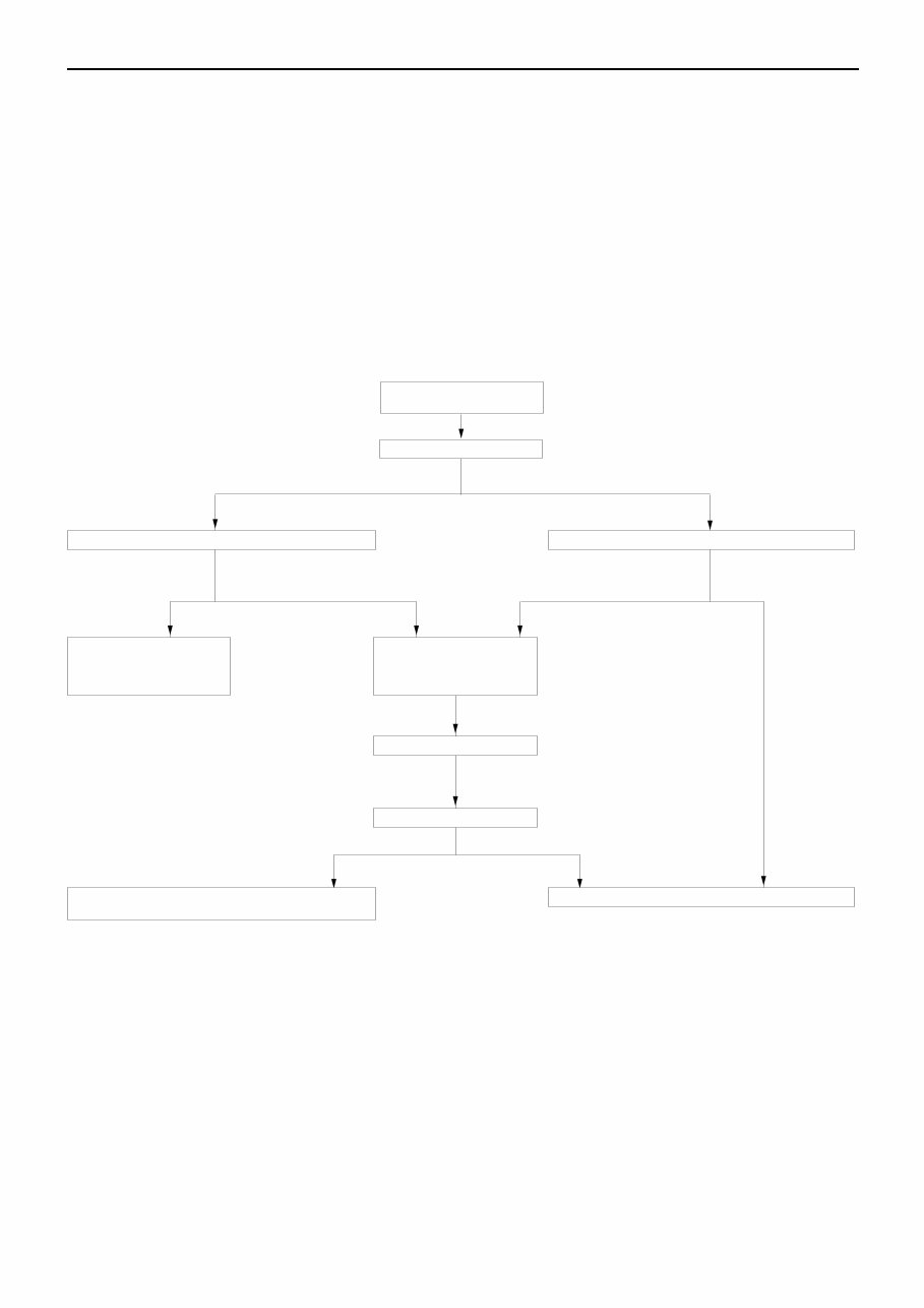
1. STANDARD FLOW OF DIAGNOSIS TROUBLESHOOTING
The troubleshooting sections follow the basic diagnosis flow which is given below. If the diagnosis
flow is different from that given below, or if additional explanation is required, the details of such
differences or additions will also be listed.
Diagnosis method
Gathering information
from the customer.
Check trouble symptom.
Reoccurs Does not reoccur.
Read the diagnosis code
No diagnosis code
or communication
with MUT-II not
possible
Refer to the INSPECTION
CHART FOR TROUBLE
SYMPTOMS (Refer to
applicable group.)
Diagnosis code
displayed.
Read the diagnosis code
Diagnosis code
displayed.
No diagnosis
code
After taking note of the
malfunction code, erase
the diagnosis code
memory
Recheck trouble symptom.
Diagnosis code
displayed.
Read the diagnosis codes.
No diagnosis
code
Refer to the INSPECTION CHART FOR DIAGNOSIS
CODES (Refer to applicable group.)
INTERMITTENT MALFUNCTIONS (Refer to P.00-12.)
2. SYSTEM OPERATION AND SYMPTOM VERIFICATION TESTS
If verification of the trouble symptoms is difficult, procedures for checking operation and verifying
trouble symptoms are shown.
3. DIAGNOSIS FUNCTION
Details which are different from those in the “Diagnosis Function” section on the next page are listed.
GENERAL – How to Use Troubleshooting/Inspection Service Points 00-7
4. INSPECTION CHART FOR DIAGNOSIS CODES
5. INSPECTION PROCEDURE FOR DIAGNOSIS CODES
Indicates the inspection procedures corresponding to each diagnosis code. (Refer to P.00-9 for how
to read the inspection procedures.)
6. INSPECTION CHART FOR TROUBLE SYMPTOMS
If there are trouble symptoms even though the results of inspection using the MUT-II show that all
diagnosis codes are normal, inspection procedures for each trouble symptom will be found by means
of this chart.
7. INSPECTION PROCEDURE FOR TROUBLE SYMPTOM
Indicates the inspection procedures corresponding to each trouble symptoms classified in the Inspection
Chart for Trouble Symptoms. (Refer to P.00-9 for how to read the inspection procedures.)
8. SERVICE DATA REFERENCE TABLE
Inspection items and normal judgement values have been provided in this chart as reference information.
9. CHECK AT ECU TERMINALS
Terminal numbers for the ECU connectors, inspection items and standard values have been provided
in this chart as reference information.
10. INSPECTION PROCEDURES USING AN OSCILLOSCOPE
When there are inspection procedures using an oscilloscope, these are listed here.
DIAGNOSIS FUNCTION
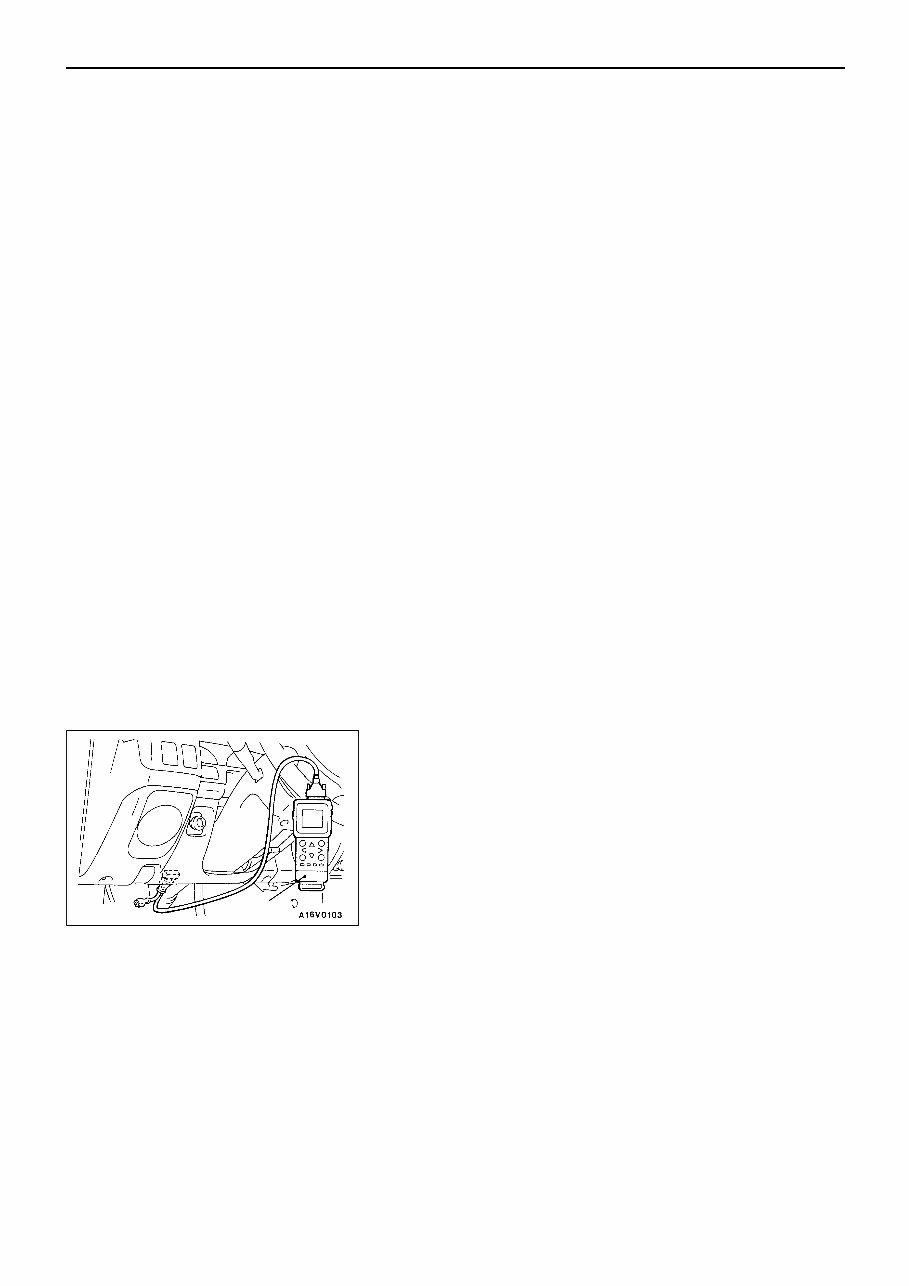
METHOD OF READING DIAGNOSIS CODES
WHEN USING THE MUT-II
Connect the MUT-II to the diagnosis connector and take a
reading of the diagnosis codes.
Caution
Turn off the ignition switch before connecting or
disconnecting the MUT-II.
MUT-II
GENERAL – How to Use Troubleshooting/Inspection Service Points 00-8
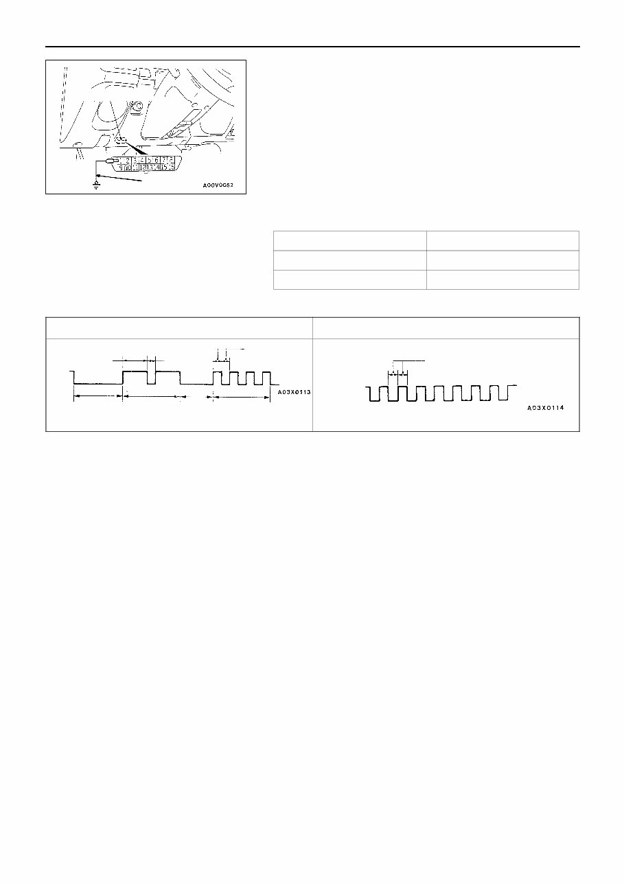
WHEN USING THE WARNING LAMP
1. Use the special tool to earth No.1 terminal (diagnosis
control terminal) of the diagnosis connector.
2. To check ABS system, remove the valve relay.
NOTE
That is because the valve relay is off and the warning
lamp remains illuminated if there is a fault in the ABS
system.
3. Turn off the ignition switch.
4. Read out a diagnosis code by observing how the warning
lamp flashes.
Applicable systems
System name Warning lamp name
MPI Engine warning lamp
ABS ABS warning lamp
Indication of diagnosis code by warning lamp
When the diagnosis code No.24 is output When no diagnosis code is output*
On
Off
1.5 s 0.5 s
0.5 s
Pause
time 3 s
Tens
signal
Place
division
2 s
Units
signal
On
Off
0.5 s
NOTE
*: Even if the ABS system is normal, removing the valve relay causes the diagnosis code No.51 to
be output.
METHOD OF ERASING DIAGNOSIS CODES
WHEN USING THE MUT-II
Connect the MUT-II to the diagnosis connector and erase the diagnosis code.
Caution
Turn off the ignition switch before connecting or disconnecting the MUT-II.
WHEN NOT USING THE MUT-II
(1) Turn the ignition switch to OFF.
(2) After disconnecting the battery cable from the battery (–) terminal for 10 seconds or more, reconnect
the cable.
(3) After the engine has warmed up, run it at idle for about 15 minutes.
Diagnosis connector
MB991529
GENERAL – How to Use Troubleshooting/Inspection Service Points
00-9
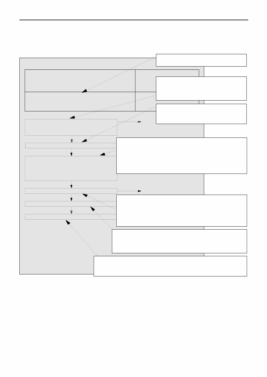
HOW TO USE THE INSPECTION PROCEDURES
The causes of a high frequency of problems occurring in electronic circuitry are generally the connectors,
components, the ECU and the harnesses between connectors, in that order. These inspection procedures
follow this order, and they first try to discover a problem with a connector or a defective component.
D Indicator does not turn on or off even if control
mode switch is pressed.
D Indicator switch should not be illuminated is
illuminated.
Probable cause
OK
OK
OK
Measure at switch connector A-44
D Disconnect the connector, and measure at the harness
side.
D Voltage between terminal 6 – earth and terminal 8 –
earth
OK: Approx. 5V
OK
NG
Check the following connector. A-44 Repair
OK
Check trouble symptom.
Replace the ECS-ECU.
In the above cases, the ECS switch circuit is defective or the indicator
circuit is defective.
CHECKING PROCEDURE 4
2. Indicates inspection carried out using the
MUT-II.
Indicates the operation and inspection proce-
dures.
Indicates the OK judgement conditions.
3. Detailed inspection procedures (methods)
such as component inspection and circuit
inspection are listed on a separate page, and
are given here for reference.
5. Inspect the contact condition at each connector terminal.
(Refer to Connector Inspection Service Points.)
The connector position can be located in the wiring diagram in the
electrical wiring manual by means of this symbol.
Caution
After carrying out connector inspection, always be sure to
reconnect the connector as it was before.
6. Confirm that there are trouble symptoms. If trouble symptoms have
disappeared, the connector may have been inserted incorrectly and the
trouble symptom may have disappeared during inspection.
If it seems that trouble symptoms still remain, proceed to the next page of
instructions.
7. If trouble symptoms still remain up to this stage, there is a possibility that there is an
open or short circuit in the harness between the connectors, so check the harness.
Alternatively, the cause may be a defective ECU, so try replacing the ECU and check
if the trouble symptom disappears.
NG
ECU switch component inspection (Refer to P.3-44.)
NG
1. Comments on the diagnosis code or trouble
symptom above.
MUT-II Data list
17 Control mode selection switch
OK: Voltage changes between approx. 0V ! approx.
2.5V ! approx. 5V when the switch is operated.
4. Indicates voltage and resistance to be measured at a particular
connector.
(Refer to Connector Measurement Service Points.)
The connector position can be located in the wiring diagram in the
electrical wiring manual by means of this symbol.
Indicates operation and inspection procedures, inspection terminals
and inspection conditions.
Indicates the OK judgement conditions.
HARNESS INSPECTION
Check for an open or short circuit in the harness between the terminals which were defective according
to the connector measurements. Carry out this inspection while referring to the electrical wiring manual.
Here, “Check harness between power supply and terminal xx” also includes checking for blown fuses.
For inspection service points when there is a blown fuse, refer to “Inspection Service Points for a Blown
Fuse.”
MEASURES TO TAKE AFTER REPLACING THE ECU
If the trouble symptoms have not disappeared even after replacing the ECU, repeat the inspection procedure
from the beginning.
You're Reading a Preview
What's Included?
Fast Download Speeds
Offline Viewing
Access Contents & Bookmarks
Full Search Facility
Print one or all pages of your manual
$33.99
Viewed 82 Times Today


Secure transaction
What's Included?
Fast Download Speeds
Offline Viewing
Access Contents & Bookmarks
Full Search Facility
Print one or all pages of your manual
$33.99
This repair service manual is designed for the Mitsubishi L200 MK Triton 2WD-4WD UTE, covering the years 1997-2002. It provides comprehensive information on the following engines:
- 4G63 2.0L PETROL
- 4G64 2.4L PETROL
- 6G72/4 3.0-3.5L V6 PETROL
- 4D56 2.5L DIESEL
- 4M40 2.8L TURBO DIESEL
- 4M41 3.2L TURBO DIESEL
This manual covers both 2WD and 4WD configurations, including UTE and DUALCAB models. It includes detailed information on various aspects, such as:
- General
- Engine Petrol-Diesel
- Engine Lubrication
- Fuel System Petrol and Diesel
- Engine Cooling System
- Intake and Exhaust
- Engine Electrical System
- Engine and Emission Control
- Clutch Mechanism
- Manual Transmission 2wd-and 4wd
- Automatic Transmission 4speed Auto
- Propeller Shaft
- Front Axle 2-4wd
- Rear Axle
- Wheel and Tyre
- Engine Mounts
- Front Suspension
- Rear Suspension
- Service Brakes and ABS
- Parking Brakes
- Power Steering
- Body-Ute-Dualcab
- Exterior Fittings
- Interior and Supplemental Restraint Systems
- Chassis Electrical System
- Anti-Skid braking system (ABS) 2WD
- Anti-Skid braking system (ABS) 4WD
- Heater
- Air Conditioner
- Ventilation
Whether you are a professional mechanic or a DIY enthusiast, this manual provides the essential technical information required for repair and maintenance of the Mitsubishi L200 MK Triton 2WD-4WD UTE from 1997 to 2002.


