Service Manual CONQUEST L Volume-l -~~~~~~- Engine, - Chassis & Body ._ FoREWoRD . ,. “” 1.“. This Service Manual has been prepared with the latest service information available at the time of publication. It is subdivided into various group categories and each section contains diagnosis, disassembly, repair, and installation procedures along with complete specifications and tightening references. Use, of this manual will aid in properly performG-rg any .servicing’ necessary to maintain or restore the high levels of performance and reliability designed jnto these outstanding vehicles. -.. ‘..,Z Introduction and Master Troubleshooting ***-**0*-**0**~~* Lubrication and Maintenance ........ mnt Suspension .................................. ..... ~ . h, Rear Axle ............................................ E- Service Brakes - Parking ........ ........................ m Clutch .................................................... m- i Cooling .......................................... -f .... m-~ sic - Engine -’ 5 ?L. -- .................................................... 0 -jj-“. .-y; ,.+.,,i ‘&I ,?;.“I,: -;.q ‘- ~ ; *l .:.>;:q; < .I- E . Intake and Exhaust System -, ............ _I ---; mi# Fuel System ................ <....................... 5 L-- -- mimp ia= Propeller Shaft and Universal Joints .................-........i.r......-..r.i .........r... ;===-% &I ,b .~ .b -- Rear Suspension ..................... . ........... mr . Body .................................................... 2. :_ .I J!!i!B , .c:. .’+ : ; ‘$ i_.... Heaters and Air Conditioning ........ WZ A- _r ; Chrysler Motors reserves the right to make changes in design or~to. make additions to or improvements in its prodlicts without imposing- any obligations upon jtself to install them on its products previously manufactured,* @ 1987 Mitsubishi Motors Corp&ation Printed in Japan Emission Control Systems ............ pz; I__
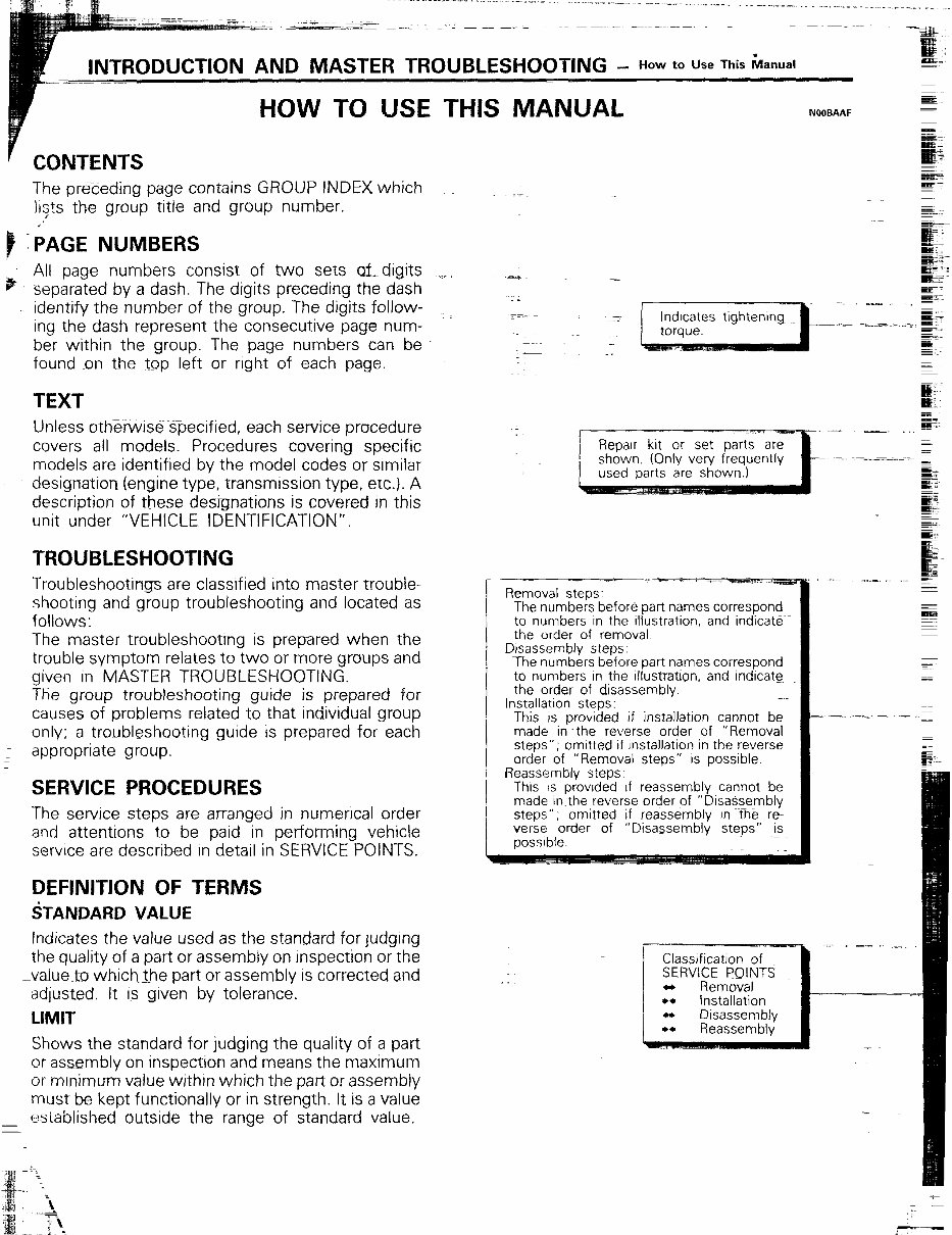
_ How to Use This Manual HOW TO USE THIS MANUAL ’ CONTENTS The preceding page contains GROUP INDEX which lists the group title and group number. *’ - iAGE NUMBERS p All page numbers consist of two sets &digits separated by a dash. The digits preceding the dash -identify the number of the group. The digits follow- ing the dash represent the consecutive page num- ber within the group. The page numbers can be found on the top left or right of each page. TEXT Unless otherwise specified, each service procedure covers all models. Procedures covering specific models are identified by the model codes or similar designation (engine type, transmission type, etc.). A description of these designations is covered in this unit under “VEHICLE IDENTIFICATION”. TROUBLESHOOTING Troubleshootings are classified into master trouble- shooting and group troubleshooting and located as follows: The master troubleshooting is prepared when the trouble symptom relates to two or more groups and given in MASTER TROUBLESHOOTING. The group troubleshooting guide is prepared for causes of problems related to that individual group only; a troubleshooting guide IS prepared for each I appropriate group. SERVICE PROCEDURES The service steps are arranged in numencal order and attentions to be paid in performing vehicle service are described in detail in SERVICE POINTS. DEFINITION OF TERMS STANDARD VALUE Indicates the value used as the standard for judging the quality of a part or assembly on inspection or the -_value~to which the part or assembly is corrected and adjusted. It is given by tolerance. LIMIT Shows the standard for judging the quality of a part or assembly on inspection and means the maximum or minimum value within which the part or assembly must be k_ept functionally or in strength. It is a value ~~ esiablished outside the range of standard value. Repair kit or set parts are shown. (Only very frequently used parts are shown.) Removal steps: The numbers before part names correspond to numbers In the illustration. and indicate the order of removal. Disassembly steps. The numbers before part names correspond to numbers In the illustration, and indicate the order of disassembly. Installation steps: This is provided if installation cannot be made in the reverse order of “Remov& steps”; omitted if rnstallation in the reverse order of “Removal steps” is possible. Reassembly steps: This IS provrded if reassembly cannot be made In the reverse order of “Disa$sembly- steps” ; omitted If reassembly in the r& verse order of “Disassembly steps” is possible. Classification of SERVICE POINTS - Removal * Disassembl
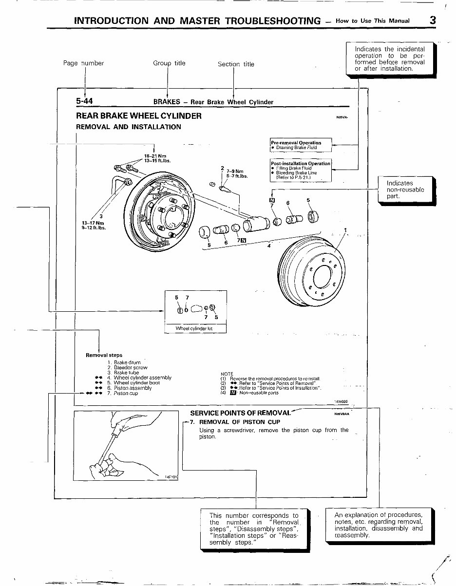
INTRODUCTION AND MASTER TROUBLESHOOTING - How *o “se This Ma”ua’ 3 Page number Group title I I Sectipn title i I BRAKES - Rear Brake Wheel Cvlinder Indicates the incidental operation to be. per- formed before removal or after installation. I - - REAR BRAKE WHEEL CYLINDER N05”A- REMOVAL AND INSTALLATION . Dravvng Brake Fluid 18-21 Nm ,..-/ 13-15ft.lbs. Post-installation Operation pi2jijq-J 1 Wheel cylinder kit I Removal steps 1. Brakedrum 2. Bleeder screw 3. Brake tube *+ 4. Wheel cylinder assembly +e 5. Wheel cyhnder boot l * 6. Piston assembly - l * l * 7. Piston cup NOTE (1) Reverse the removal procedures to reinstall. (2) a*: Refer to “Service Points of Removal”. (3) *a: Refer to “Service Points of Installation”. 14) p Non-reusable parts SERVICE POINTS OF REMOVAL/ NOWBAI 7. REMOVAL OF PISTON CUP Using a screwdriver, remove the piston cup from the I This number corresponds to the number in “Removal. steps”, ” Disassembly steps”, “installation steps” or “Reas- sembly steps.” Indicates non-reusable part. installation. disassembly and
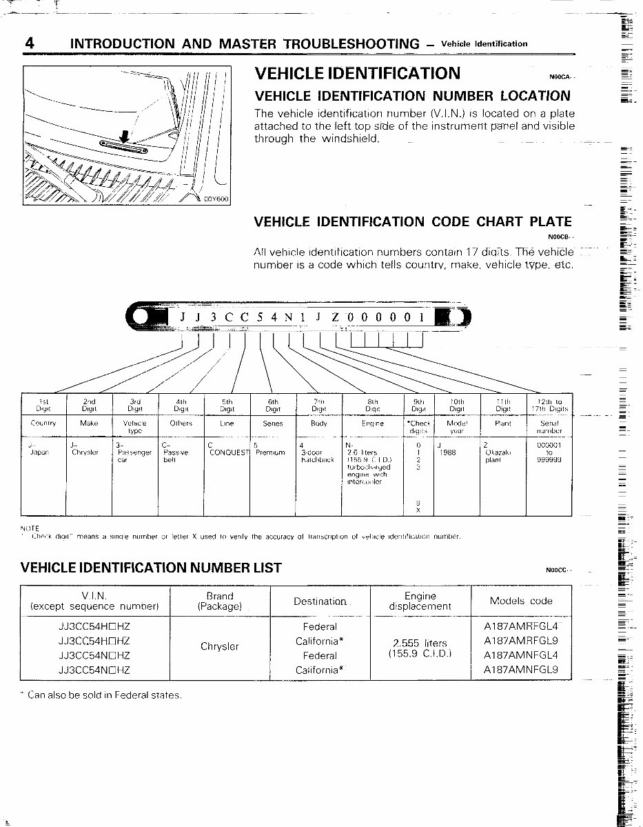
INTRODUCTION AND MASTER TROUBLESHOOTING - Vehicte Identification VEHICLE IDENTIFICATION NOOCA- VEHICLE IDENTIFICATION NUMBER LOCATION The vehicle identification number (V.I.N.) is located on a plate attached to the left top side of~the instrument panel and visible through the windshield. VEHICLE IDENTIFICATION CODE CHART PLATE NOOCB- - All vehicle identitication numbers contain 17 diaits. The vehicle = ~~ number IS a code which tells countrv, make, vehicle type, etc. ~~~~ I 0 J 2 000001 : 1988 Okazakl plant 99E399 3 C’hwk dealt” means a wale number or letter X used lo venfv the accuracy of trarwxptlon of vrlllcle Identifvzatlon number VEHICLE IDENTIFICATION NUMBER LIST V.I.N. Brand (except sequence number) (Package) DeStinatiQn JJ3CC54HOHZ Federal JJXC64HOHZ Chrysler California* JJ3CC54NOHZ Federal JJ3CC54NCIHZ California’ - Can also be sold In Federal states, NOOCC- - Engine displacement Models code 2.555 liters (155.9 C.I.D.) Al 87AMRFGL4 Al 87AMRFGL9 Al 87AMNFGL4 Al 87AMNFGL9
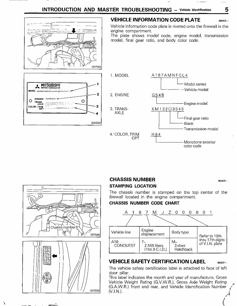
INTRODUCTION AND MASTER TROUBLESHOOTING - Vehicle identification 5 VEHICLE INFORMATION CODE PiATE NOOCD- - Vehicle information code plate is riveted onto the firewall in the engine compartment. The plate shows model code, engine model, transmission model, final gear ratio, and body color code. 1. MODEL 2. ENGINE 3. TRANS- AXLE 4:COLOR, TRIM OPT A187AMNFGL4 ---lIT~:;:l,,n,,i G54B I Engine model KM 132Cl3545 -iI T-L Final gear ratio Blank Transmission model H84 I I Monotone exterior color code CHASSIS NUMBER NOOCE- . STAMPING LOCATION The chassis number is stamped on the top center of the firewall located in the engine compartment. CHASSIS NUMBER CODE CHART A187MJZ000001 Vehicle line Engine displacement Body type Refer to 10th A18- 7- M- thru 17th digits CONQUEST 2.555 liters 2-door of V.I.N. plate (155.9 C.I.D.) Hatchback VEHICLE SAFETY CERTIFICATION LABEL NOOCF- - The vehicle safety certification label is attached to face of left door pillar. This label indicates the month and year of manufacture, Gross Vehicle Weight Rating (G.V.W.R.), Gross Axle Weight Rating [(&k$/.R.) front and rear, and Vehicle Identification Number F~ . . . . i x I
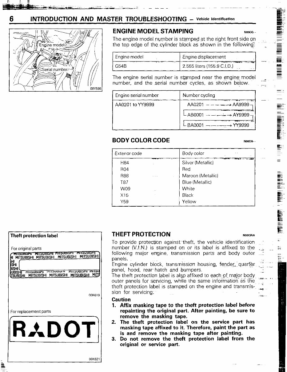
6 INTRODUCTION AND MASTER TROUBLESHOOTING - Vehicle identification Theft protection label For ori$nal parts OOK619 For replacement parts OOK621 ENGINE MODEL STAMPING NOOCG.. The engine model number is stmped at the right front side on the top edge of the cylinder block as shown in the followlng: .Engine displacement The engine serial number is samped near the engin model number, and the serial number cycles, as shown below. Engine serial number BODY COLOR CODE Exterior code R04 R88 T87 wo9 x15 Y59 e. NOOCH- . K’ Red Maroon (Metallic) Blue (Metallic) White Black Yellow NOOClAA To provide protection against -theft, the vehicle identification number (V.I.N.) is stamped on or its label is affixed ta t_he following major engine, transmission parts arrd body outer panels- Engine cylinder b&k, transmission housing, @rtder,Tquar@r panel, hood, rear hatch and bumpers. The theft protection label is aIS_o affixed to each=pf major bociy outer panels for servicing, while the same information as Ihe theft protection label is stamped on the engine and tfansmis sion for servicing: Caution 1. Affix masking tape to the theft protection label before repainting the original part. After painting, be sure to remove the masking tape. 2. The theft protection label on the service part has masking tape affixed to it. Therefore, paint the part as is and remove the masking tape after painting. 3. Do not remove the theft protection label from the original or service part.
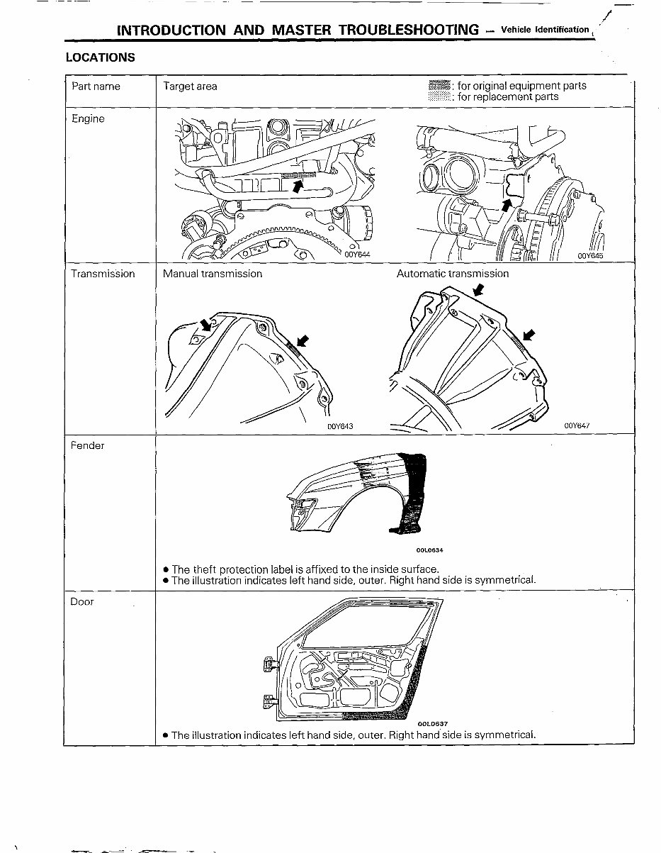
INTRODUCTION AND MASTER TROUBLESHOOTING - Vehicle Identification I ’ LOCATIONS OOLO634 l The theft protection label is affixed to the inside surface. l The illustration indicates left hand side, outer. Right hand side is symmetrical.
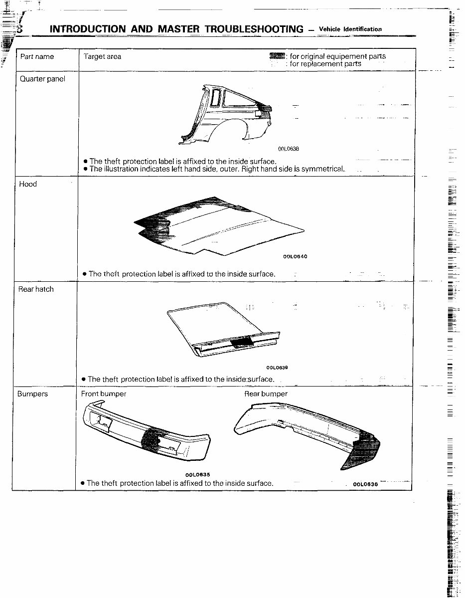
INTRODUCTION AND MASTER TROUBLESl400TING - Vehicle kkntification Part name Quarter panel Hood Rear hatch 3umpers Target area : for original equipement parts : for replacement pares - 00L0638 l The theft protection label is affixed to the inside surface. l The illustration indicates left hand side, outer. Right hand sideis symmetrical. OOL0640 l The theft protection label is affixed to the inside surface. OOL0639 l The theft protection label is affixed to the insidesurface. _ -__ i ~-~ Front bumper Rear bumper 0OL0635 D The theft protection label is affixed to the inside surface. OOL0636
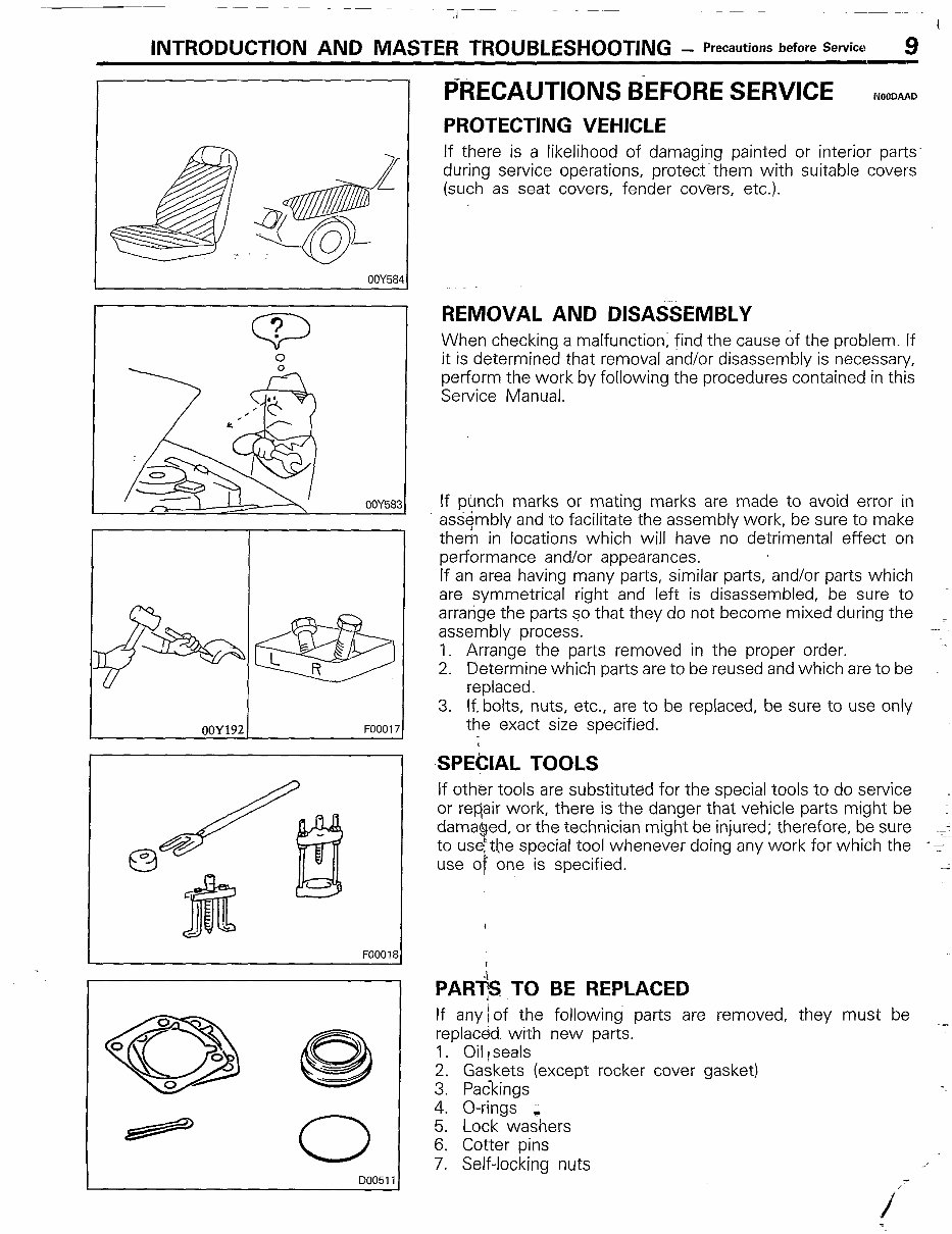
.I I INTRODUCTION AND MASTER TROUBLESHOOTING - Precautions before Service 9 OOY684 P ? 0 0 ,,’ s &fig .a< I OOY58? FOOOll 0 000511 OOY192 FOO017 3 PRECAUTIONS BEFORE SERVICE NOODAAD PROTECTING VEHICLE If there is a likelihood of damaging painted or interior parts during service operations, protects them with suitable covers (such as seat covers, fender covers, etc.). REMOVAL AND DISASSEMBLY When checking a malfunction; find the cause of the problem. If it is determined that removal and/or disassembly is necessary, perform the work by following the procedures contained in this Service Manual. If punch marks or mating marks are made to avoid error in assembly and to facilitate the assembly work, be sure to make them in locations which will have no detrimental effect on performance and/or appearances. If an area having many parts, similar parts, and/or parts which are symmetrical right and left is disassembled, be sure to arrange the parts so that they do not become mixed during the assembly process. 1. Arrange the parts removed in the proper order. 2. Determine which parts are to be reused and which are to be replaced. 3. If. bolts, nuts, etc., are to be replaced, be sure to use only the exact size specified. ,SPE(XAL TOOLS If other tools are substituted for the special tools to do service or repair work, there is the danger that vehicle parts might be damaged, or the technician might be injured; therefore, be sure to use$he special tool whenever doing any work for which the -s -- use of one is specified. PAR+ TO BE REPLACED If any rof the following parts are removed, they must be ~_ replaced with new parts. 1. Oil rseals 2. Gaskets (except rocker cover gasket) 3. Packings 4. O-rings 5. Lock wa:hers 6. Cotter pins 7. Self-locking nuts i
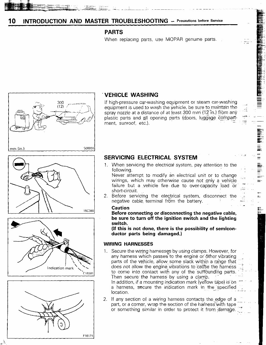
-----; -li_w - I-A.. i IO INTRODUCTION AND MASTER TROUBLESHOOTING - Precautions before Service PARTS When replacrng parts, use MCIPAR genurne parts. mm (in.) so0059 16C38( Indication ‘mark \ -\ \ L -cl6381 F16171 =VEHICLE WASHING If high-pressure car-washing equipment or steam car-washing equipment is used to wash the vehicle, be sure to maintain the :: spray nozzle at a distance of at Jeast 300 mm (12in.I from any ‘; ~~~ ;~~ plastic parts and al! opening parts (doors, !u.rgg&e @mparJ ~ ment, sunroof, etc.). ---=;-- mz% =j_- c- .- a= mw- w - SERVICING ELECTRICAL SYSTEM - 1. When servicing the electrical system, pay attention to the following. sI Never attempt. to modify an electrical unit or to change --_r G- wirings, which may otherwise cause not only a .vehicle Fe failure but a vehicle fire due to over-capacity !oad %r Z short-circuit. 2. Before servicing the- electrical system, disconnect the ‘I., z negative cables terminal fErn the battery. ’ :Z Caution _z G Before connecting or disconnecting the negative cable, be sure to turn off the ignition switch and the lighting switch. (If this is not done, there is the possibility of semicon- ductor parts being damaged.) WIRING HARNESSES 1. Secure the wiring harness9 by using clamps. However, for any harness which passes to the engine or’other vibrating parts of the vehicle, allowmVsome slack within a raj-rge that ‘= does not allow the engine_vibrations to cauEe the-harness 11: ~- to come into .contact with any of the su~F8undEig pa~rts. e - Then secure the harness- by using a clamp. ’ -em-- In addition, if a mounting indication mark (yeflow Gpe) is on c_ a harness, secure the indication mark in the-;specified -1 location. 2. If any section of a wiring harness contacts theedge of a ~-_ part, or a corner, wrap the section of the harnesswith tape or something similar in order to protect it ~from damage. _I_ .-
This workshop manual is a comprehensive guide for working on MITSUBISHI STARION-CONQUEST vehicles. It provides step-by-step instructions, clear pictures, exploded view illustrations, schematics, and specifications to assist both professional mechanics and DIY enthusiasts in their projects. The manual covers MITSUBISHI STARION TURBO (AUSTRALIAN) JA-JB-JC VOL 1 AND 2, as well as CHRYSLER CONQUEST TURBO (AMERICAN) VOLUME 1 AND 2. It includes both models in a single file for easy reading and printing. This manual encompasses the entire vehicle, from front to back, and covers all aspects comprehensively. It is designed for 2.0L and 2.6L engines, including turbocharger systems, and caters to both automatic and manual transmissions. Additionally, it includes a buyer's guide and owner's manual for added convenience.