

1999-2006 Mitsubishi Pajero NM Service & Repair Manual
What's Included?
Fast Download Speeds
Offline Viewing
Access Contents & Bookmarks
Full Search Facility
Print one or all pages of your manual

DIESEL FUEL
<4D5-STEP III>
Click on the applicable bookmark to selected the required model year.

13E-1
DIESEL FUEL
<4D5-STEP III>
CONTENTS
GENERAL 2 .................................
Outline of Change 2 ............................
GENERAL INFORMATION 2 ...................
SERVICE SPECIFICATIONS 4 .................
SEALANT 4 ..................................
SPECIAL TOOLS 5 ...........................
TROUBLESHOOTING 6 .......................
ON-VEHICLE SERVICE 55 ....................
Injection Nozzle Check and Adjustment 55 .........
Injection Timing Check and Adjustment 55 .........
Idle Speed Check and Adjustment 55 .............
Accelerator Pedal Position Sensor (APS)
Adjustment 56 .................................
Control Relay Continuity Check 57 ................
Accelerator Pedal Position Sensor (APS)
Check 57 ......................................
Idle Switch Check 58 ............................
Boost Air Temperature Sensor (Intake Air
Temperature Sensor) Check 58 ..................
Engine Coolant Temperature Sensor Check 59 .....
Evacuation of Water from Fuel Filter 59 ............
Fuel Filter Cartridge Replacement 60 ..............
Evacuation of Air from Fuel Line 60 ...............
EGR Valve Position Sensor Check 60 .............
Fuel Injection Pump Check 61 ....................
Throttle Solenoid Valve Check 62 .................
Throttle Actuator Check 63 ......................
Variable Geometry Solenoid Valve Check 63 .......
EGR Control Solenoid Valve Check 63 ............
FUEL INJECTION NOZZLE 64 .................
FUEL INJECTION PUMP 64 ...................
CRANKSHAFT POSITION SENSOR 66 .........
ENGINE-ECU 66 .............................

DIESEL FUEL <4D5-step III>- General/General Information 13E-2
GENERAL
OUTLINE OF CHANGE
An electronically-controlled injection pump has been added in order to comply with Regulation STEP
III. Due to this, the following service procedures have been added.
GENERAL INFORMATION
The electronically-controlled fuel injection system consists of sensors which detect the condition of the
diesel engine, an engine-ECU which controls the system based on signals from these sensors, and actuators
which operate according to control commands from the engine-ECU.
The engine-ECU carries out operations such as fuel injection rate control, fuel injection timing control
and idle up control. In addition, the engine-ECU is equipped with several self-diagnosis functions which
make troubleshooting easier in the event that a problem develops.
FUEL INJECTION RATE CONTROL
The fuel injection completion timing is controlled by means of a solenoid-type spill valve to ensure that
the optimum amount of fuel is supplied to the engine in accordance with gradual changes in the engine
running condition.
Before fuel injection starts, the solenoid-type spill valve is on (energized), so that the valve is closed.
As the plunger turns and rises, fuel is sent out under pressure, and when the fuel flow rate reaches
the target value for fuel injection, the solenoid-type spill valve turns off. When the solenoid-type spill
valve turns off, the fuel under high pressure inside the plunger is leaked out into the pump chamber
and fuel injection is completed.
FUEL INJECTION TIMING CONTROL
The position of the injection pump timer piston is controlled so that fuel injection is carried out at the
optimum timing in accordance with the engine running condition.
The timer piston position is determined by duty control of the timing control solenoid valve which is located
in the line between the high-pressure chamber and the low-pressure chamber of the timer piston.
The fuel injection timing is advanced by increasing the control duty of the timing control solenoid valve.
IDLE SPEED CONTROL
Controlling the fuel injection rate in accordance with the engine running condition maintains the idle speed
at the optimum condition.
SELF-DIAGNOSIS FUNCTION
D When an abnormality is detected in any of the sensors or actuators, the engine warning lamp illuminates
to warn the driver.
D When an abnormality is detected in any of the sensors or actuators, a diagnosis code number
corresponding to the problem which occurred is output.
D The RAM data relating to the sensors and actuators which is stored in the engine-ECU can be read
using the MUT-II. In addition, the actuators can be force-driven under certain conditions.
OTHER CONTROL FUNCTIONS
1. Power Supply Control
When the ignition switch is turned to ON, the relay turns on and power is supplied to components
such as the timing control solenoid valve.
2. Intake Air Throttle Control
When the engine-ECU detects an abnormality in any of the sensors or actuators, the throttle valve
is half opened to restrict the amount of intake air in order to prevent the vehicle from running away.
3. A/C Relay Control
Turns the compressor clutch of the A/C ON and OFF
4. Condenser Fan Motor Relay Control
Controls the condenser fan motor relay based on the A/C switch, engine coolant temperature and
vehicle speed input signals.
5. Glow Control
Refer to GROUP 16.
6. EGR Control
Refer to GROUP 17.
DIESEL FUEL <4D5-step III>- General Information 13E-3
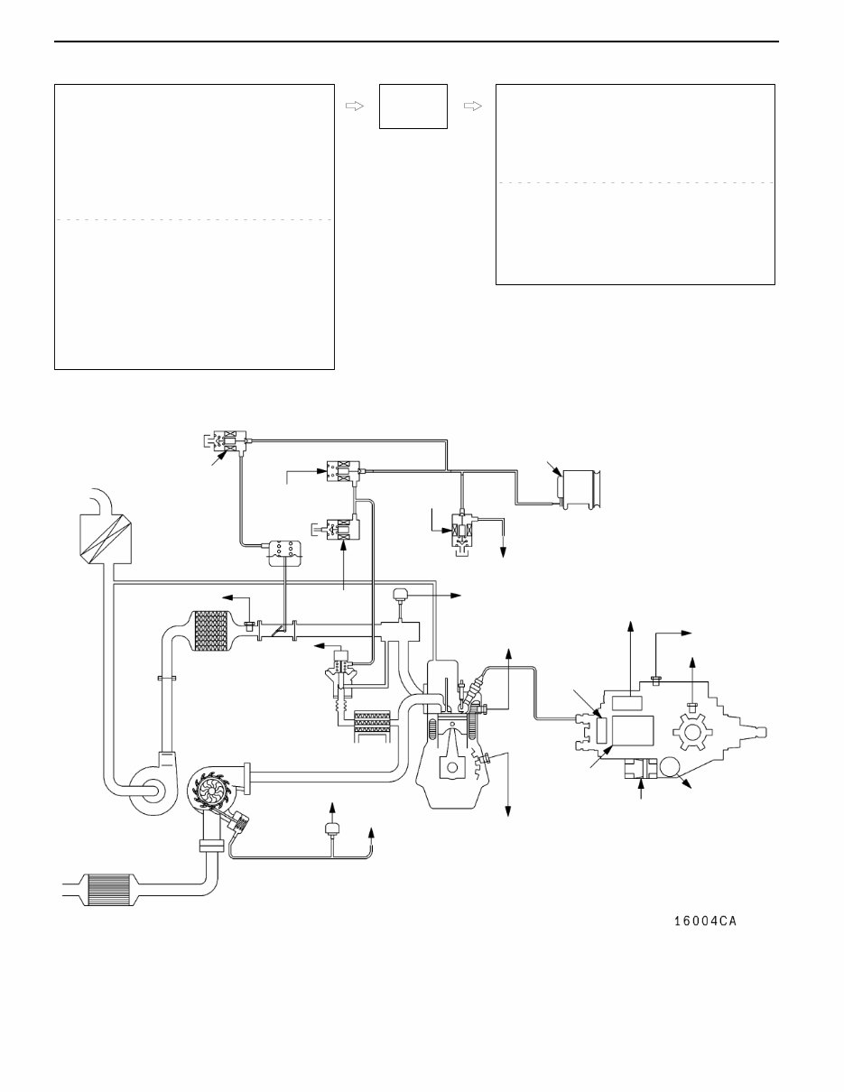
CONTROL SYSTEM DIAGRAM
L1. Pump speed sensor
L2. Crank angle sensor
L3. Engine coolant temperature sensor
L4. Boost pressure sensor
L5. Fuel temperature sensor
L6. Boost air temperature sensor
L7. Control sleeve position sensor
L8. Timer piston position sensor
L9. EGR valve position sensor
L10. Variable geometry control pressure sensor
D Accelerator pedal position sensor (main)
D Accelerator pedal position sensor (sub)
D Idle switch
D Power supply
D Ignition switch-IG
D Ignition switch-ST
D Vehicle speed sensor
D A/C switch
D A/C relay switch
D Injection volume adjusting ROM
D Barometric pressure sensor (ECU built-in)
l1. GE actuator (electronic governor)
l2. Timing control valve
l3. EGR control solenoid valve No. 1
l4. EGR control solenoid valve No. 2
l5. Throttle solenoid valve
l6. Fuel cut solenoid valve
l7. Variable geometry solenoid valve
D Control relay
D A/C relay
D Condenser fan relay
D Glow indicator lamp
D Glow plug relay
D Engine warning lamp
D Diagnosis output
Engine-
ECU
L8 Timer piston
position
sensor
L2 Crank angle
sensor
L9 EGR
valve position
sensor
L10 Variable geometry control
pressure sensor
L6 Boost air
temperature sensor
L4 Boost pressure
sensor
L3 Engine coolant
temperature sensor
L7 Control
sleeve
position
sensor
l7
Variable geometry
solenoid valve
l3
EGR control
solenoid valve No. 1
l1 GE actuator
l5 Throttle solenoid valve
l6 Fuel cut
solenoid
valve
Vacuum pump
Alternator
To variable
geometry actuator
l2 Timing control
valve
Catalytic converter
Variable
geometry
actuator
Variable geometry
turbocharger
Throttle
actuator
EGR valve
To variable geome-
try solenoid valve
L1 Pump speed
sensor
L5 Fuel
temperature
sensor
l4 EGR control
solenoid
valve No. 2
DIESEL FUEL <4D5-step III>- Service Specifications/Sealant 13E-4
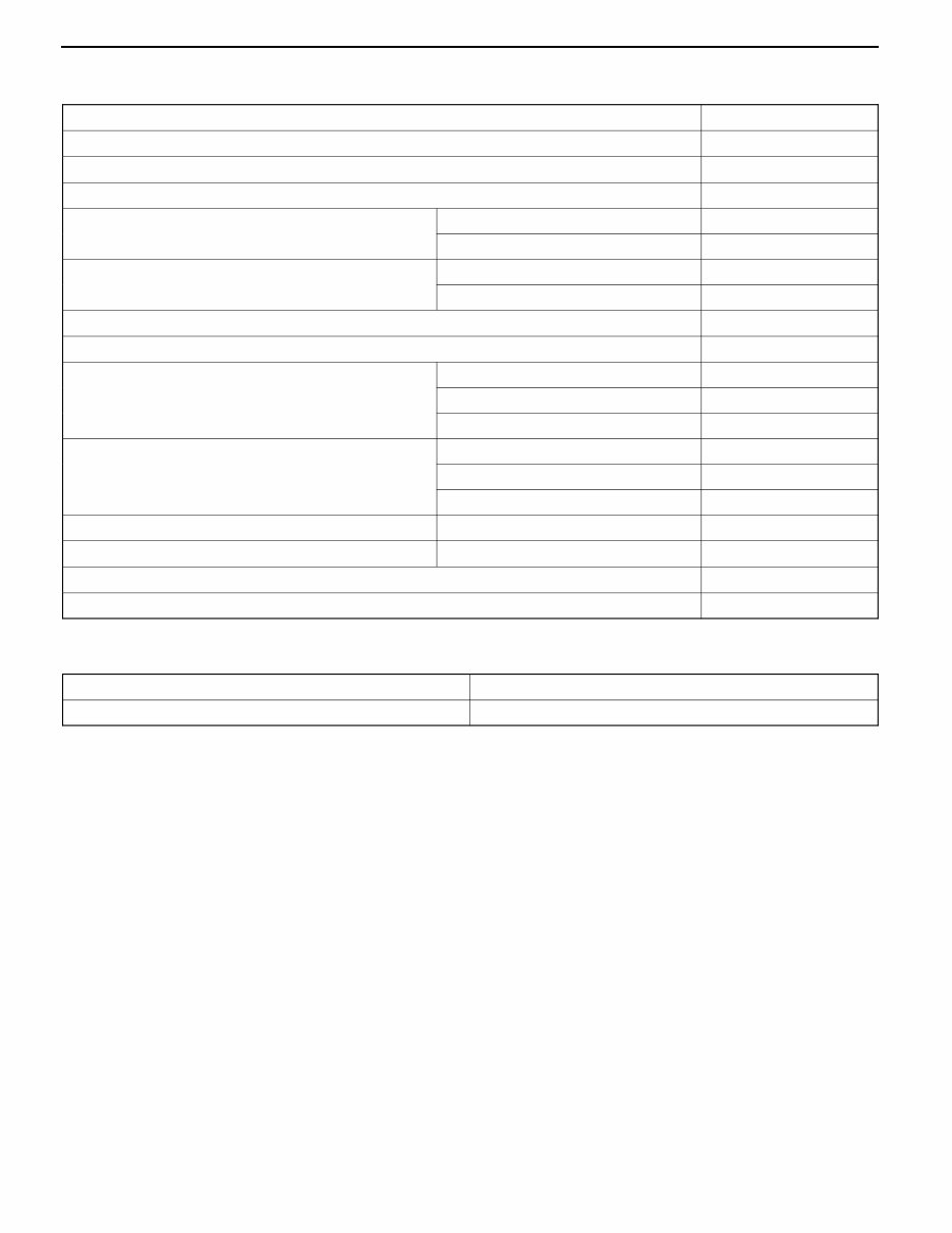
SERVICE SPECIFICATIONS
Item Standard value
Fuel injection initial pressure kPa 14,710 - 15,490
Accelerator pedal position sensor reference voltage V 0.985 - 1.085
Accelerator pedal position sensor resistance kΩ 3.5 - 6.5
Boost air temperature sensor (Intake air temperature
) it kΩ
When the temperature is 20_C 2.3 - 3.0
sensor) resistance kΩ
When the temperature is 80_C 0.30 - 0.42
Engine coolant temperature sensor resistance kΩ When the temperature is 20_C 2.1 - 2.7
When the temperature is 80_C 0.26 - 0.36
Fuel cut solenoid valve resistance Ω 6.8 - 9.2
Timing control valve resistance Ω 10.8 - 11.2
Timer piston position sensor resistance Ω Connector terminals No. 1 - No. 2 160 - 168
Connector terminals No. 1 - No. 3 80 - 84
Connector terminals No. 2 - No. 3 80 - 84
Control sleeve position sensor resistance Ω Connector terminals No. 4 - No. 12 11.2 - 12.4
Connector terminals No. 4 - No. 8 5.6 - 6.2
Connector terminals No. 8 - No. 12 5.6 - 6.2
GE actuator (electronic governor) resistance Ω Connector terminals No. 6 - No. 10 0.64 - 0.72
Fuel temperature sensor resistance kΩ Connector terminals No. 7 - No. 11 1.4 - 2.6
Pump speed sensor resistance kΩ 1.36 - 1.84
Throttle solenoid valve resistance Ω 36 - 44
SEALANT
Item Specified sealant
Engine coolant temperature sensor 3M Nut Locking Part No. 4171 or equivalent
DIESEL FUEL <4D5-step III>- Special Tools 13E-5
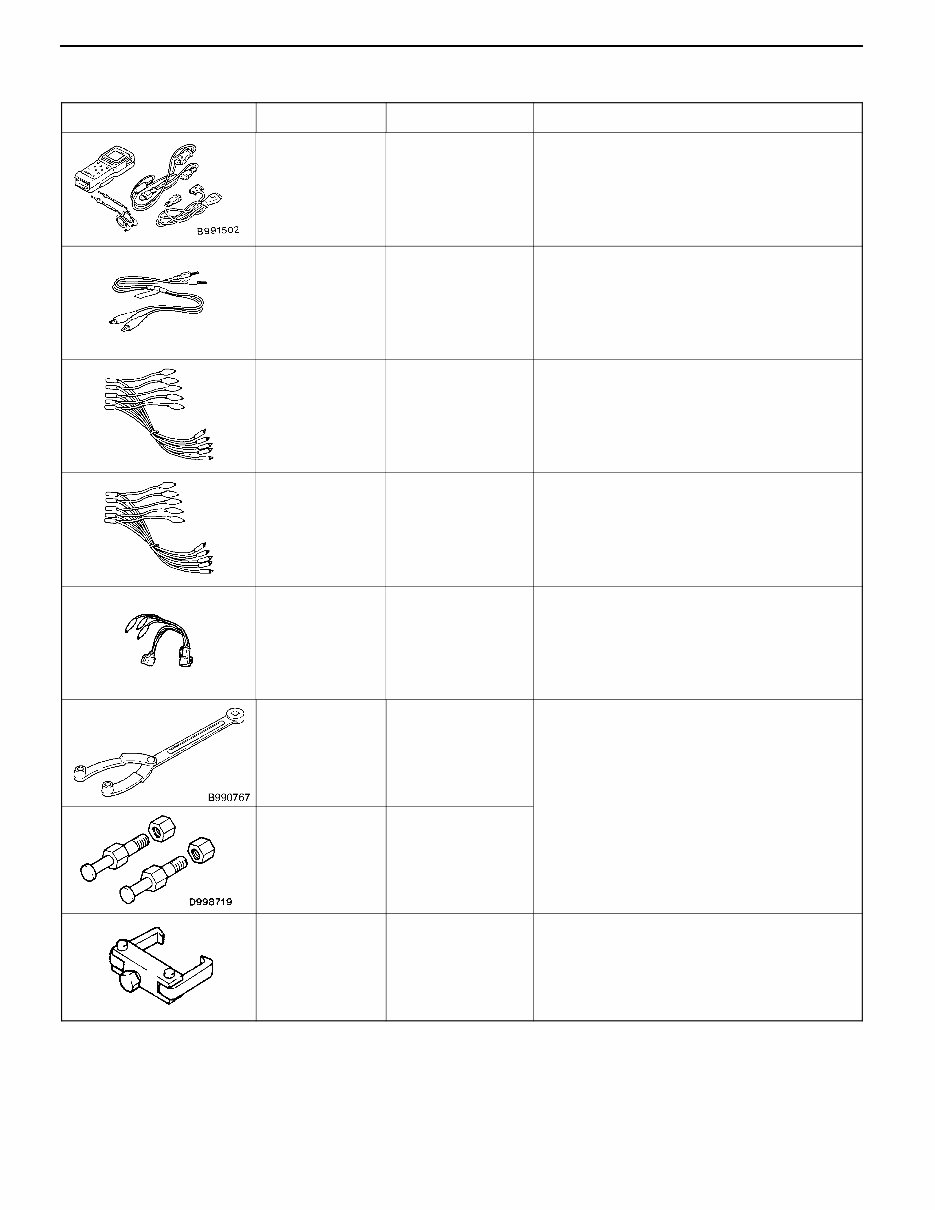
SPECIAL TOOLS
Tools Number Name Application
MB991502 MUT-II sub
assembly
Electronically controlled fuel injection system
check
MB991529 Diagnosis code
check harness
Diagnosis code reading
MB991348 Test harness set D Boost pressure sensor check
D Variable geometry control pressure sensor
check
MB991658 Test harness set D APS adjustment
D Inspection using an analyzer
MD998478 Test harness
(3-pin, square)
D Crank angle sensor check
D Inspection using an analyzer
MB990767 End yoke holder Holding the fuel injection pump sprocket
MD998719 Crankshaft pulley
holder pin
MD998388 Injection pump
sprocket puller
Fuel injection pump sprocket removal
DIESEL FUEL <4D5-step III>- Troubleshooting 13E-6
TROUBLESHOOTING
STANDARD FLOW OF DIAGNOSTIC
TROUBLESHOOTING
Refer to GROUP 00 - How to Use Troubleshooting/Inspection
Service Points.
NOTE
When replacing the engine-ECU, replace immobilizer-ECU
and ignition key as well at the same time.
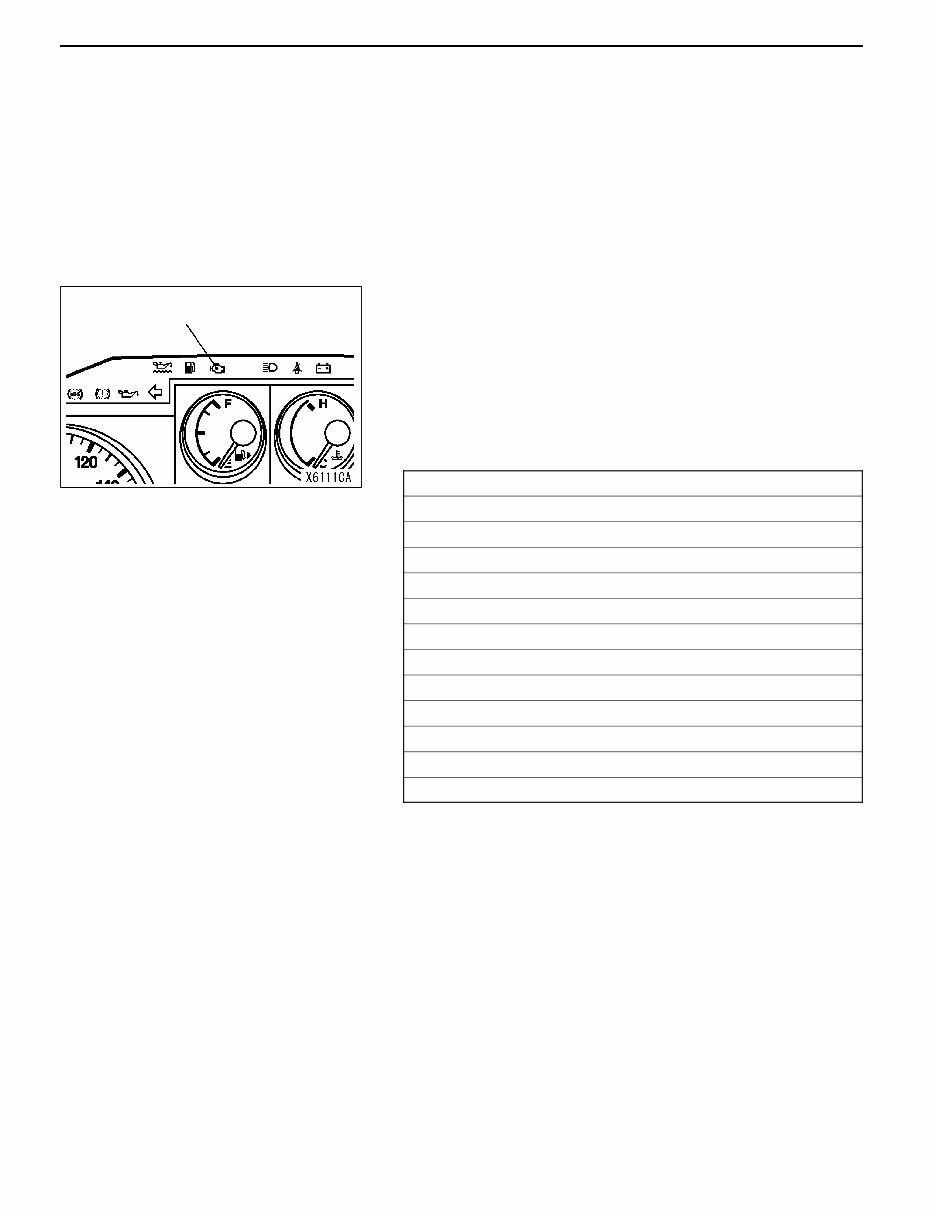
DIAGNOSIS FUNCTION
ENGINE WARNING LAMP (CHECK ENGINE LAMP)
Engine warning lamp is lit when any abnormality takes place
in the item related to electronically controlled fuel injection
system shown in the following table.
If the malfunction indicator lamp has been on and/or is lit
when the engine is in operation, check the diagnosis output.
Engine warning lamp check items
Accelerator pedal position sensor (main)
Accelerator pedal position sensor (sub)
Boost pressure sensor (Boost sensor)
Crank angle sensor
Control sleeve position sensor
Timer piston position sensor
Throttle solenoid valve
GE actuator
Variable geometry control pressure sensor
Barometric pressure sensor
Timing control valve
Idle switch
Engine-ECU
METHOD OF ERASING AND ERASING DIAGNOSIS
CODES
Refer to GROUP 00 - How to Use Troubleshooting/Inspection
Service Points.
INSPECTION USING MUT -II DATA LIST AND
ACTUATOR TESTING
1. Carry out inspection by means of the data list and the
actuator test function.
If there is an abnormality, check and repair the chassis
harnesses and components.
2. After repairing, re-check using MUT-II and check that
the abnormal input and output have returned to normal
as a result of the repairs.
3. Erase the diagnosis code memory.
4. Remove the MUT-II.
5. Start the engine again and carry out a road test to confirm
that the problem has disappeared.
Engine warning lamp
(check engine lamp)

DIESEL FUEL <4D5-step III>- Troubleshooting 13E-7
FAIL-SAFE, BACKUP FUNCTIONS
When abnormalities in the major sensors are detected by diagnosis functions, pre-set control logic operates
to maintain a safe driving condition for the vehicle.
Diagnosis item Control features in malfunction
Accelerator pedal position sensor D Accelerator pedal released (idle switch ON)
Acceleration opening degree = 0 %
D Accelerator pedal applied (idle switch OFF)
Engine controlled at low speed
Acceleration opening degree = 30 % fixed
D Void EGR control
Idle switch Void idling speed control.
Engine speed sensor D Engine controlled at low speed
D Void EGR control
D Void variable geometry turbocharger control
Boost air temperature sensor D Maintain the intake air temperature at 50_C.
D Void EGR control
Vehicle speed sensor D Void idling speed control.
D Void EGR control
Engine coolant temperature sensor D Maintain the engine coolant temperature at 80_C (However, the system
assumes the coolant temperature as 0_C).
D Void EGR control
Control sleeve position sensor D Engine controlled at low speed
D Void EGR control
D Void variable geometry turbocharger control
Timer piston position sensor D Injection timing stabilizing control
D Void EGR control
Barometric pressure sensor (ECU
built-in)
D Keep the barometric pressure at 101 kPa.
D Void EGR control
D Void variable geometry turbocharger control
Fuel temperature sensor Maintain the fuel temperature at 40_C.
Boost pressure sensor D Keep the boost pressure as barometric pressure (101 kPa).
D Void EGR control
D Void variable geometry turbocharger control
Injection volume adjusting ROM Void correction.
GE actuator D Engine controlled at low speed
D Void EGR control
D Void variable geometry turbocharger control
Over boost D Void variable geometry turbocharger control
D Engine controlled at low fuel injection
Timing control valve D Injection timing stabilizing control
D Void EGR control
EGR valve position sensor Void EGR control
Variable geometry control pressure
sensor
D Void EGR control
D Void variable geometry turbocharger control

DIESEL FUEL <4D5-step III>- Troubleshooting 13E-8
INSPECTION CHART FOR DIAGNOSIS CODES
Code No. Diagnosis item Reference
page
11 Accelerator pedal position sensor (main) system 13E-9
12* Boost pressure sensor system 13E-10
13 Barometric pressure sensor (ECU built-in) system 13E-11
14 Fuel temperature sensor system 13E-11
15 Engine coolant temperature sensor system 13E-12
16 Boost air temperature sensor system 13E-12
17 Vehicle speed sensor system 13E-13
18 Pump speed sensor system 13E-14
21 Crank angle sensor system 13E-15
23 Idle switch (accelerator pedal position sensor built-in) system 13E-16
25* Timer piston position sensor system 13E-17
26* Control sleeve position sensor system 13E-18
27 Accelerator pedal position sensor (sub) system 13E-19
41* Throttle solenoid valve system 13E-20
43 Timing control valve system 13E-21
46 Injection volume adjusting ROM system 13E-22
48* GE actuator (in the middle of control sleeve position sensor inoperative) system 13E-23
49* Over boost (variable geometry control pressure sensor system malfunction) 13E-24
51 EGR valve position sensor system 13E-25
52 Variable geometry control pressure sensor system 13E-26
54 Immobilizer system 13E-27
Caution
If the above-mentioned diagnosis code number with the asterisks can be displayed along with another
code number in parentheses simultaneously, check the other code number before replacing the
engine-ECU.
12 (41, 49), 26 (48), 25 (43), 41 (12, 49), 48 (26), 49 (12, 41)
DIESEL FUEL <4D5-step III>- Troubleshooting 13E-9
INSPECTION PROCEDURE FOR DIAGNOSIS CODE
Code No. 11 Accelerator pedal position sensor (main)
system
Probable cause
Range of Check
D Ignition switch: ON, accelerator pedal position sensor (sub) operative, except
for during engine cranking
Set Conditions
D Accelerator pedal position sensor output voltage is as below for 1 second:
Sub side: 0.2 V or more, less than 2.5 V
Main side: 4.5 V or more
or
Sub or main side: less than 0.2 V
Range of Check
D Ignition switch: ON, except for during engine cranking
Set Conditions
D The output voltage of accelerator pedal position sensor (main and sub) for
0.2 second is 0.2 V or higher, or lower than 4.5 V and the difference in
sensor output voltage between the main and sub is 1 V or higher, or idle
switch: ON, and sensor main output voltage is 1.875 V or higher.
D Accelerator pedal position sensor inoperative
D Accelerator pedal position sensor open circuit,
short circuit, or connector contact inoperative
D Engine-ECU inoperative
NG
OK
OK
Measure at D-135 accelerator pedal position
sensor connector
D Disconnect the connector and measure
at the harness side.
D Voltage between 2 and earth
(Ignition switch: ON)
OK: 4.5 - 5.5 V
D Continuity between 1 and earth
OK: Continuity
NG
Check the following connector: D-113
NG
Repair
OK
OK
Repair
NG
Accelerator pedal position sensor check
(Refer to P.13E-57.)
Replace
Check the trouble symptoms.
Replace the engine-ECU.
NG
Check the trouble symptoms.
NG
Replace the engine-ECU.
NG
Repair Check the following connectors:
D-113, D-135
OK
NG
NG
Check the following connector: D-113
NG
Repair
OK
Check the harness between the
engine-ECU and the accelerator pedal
position sensor connector.
OK
Measure at D-113 engine-ECU connector
D Connect the connector.
D Voltage between 84 and the earth
(Ignition switch: ON)
OK: 0.9 - 1.1 V
(Throttle lever idling position)
4.1 V or higher
(Throttle lever fully opened position)
Check the harness between the
engine-ECU and the accelerator pedal
position sensor connector.
NG
Repair
NG NG NG NG NG
Check the trouble symptoms.
OK
Replace the engine-ECU.
You're Reading a Preview
What's Included?
Fast Download Speeds
Offline Viewing
Access Contents & Bookmarks
Full Search Facility
Print one or all pages of your manual
$33.99
Viewed 96 Times Today


Secure transaction
What's Included?
Fast Download Speeds
Offline Viewing
Access Contents & Bookmarks
Full Search Facility
Print one or all pages of your manual
$33.99
This workshop repair manual is for the MITSUBISHI PAJERO NM from 1999 to 2006 and covers the following engines:
- 3.5L 6G74GDI V6 ENGINE
- 2.5L 4D56 TD ENGINE
- 3.2L 4M41 Di-D ENGINE
The transmission covered includes:
- 5 SPEED MANUAL V5MT1/V5M31
- 5 SPEED AUTOMATIC V5A51
The manual includes detailed information on the following:
- GENERAL INFORMATION
- ENGINE
- ENGINE LUBRICATION
- FUEL
- ENGINE COOLING
- INTAKE AND EXHAUST
- ENGINE ELECTRICAL
- EMISSION AND ENGINE CONTROL
- CLUTCH
- AUTOMATIC TRANSMISSION
- MANUAL TRANSMISSION
- PROPELLER SHAFT
- FRONT AXLE
- REAR AXLE
- WHEEL AND TYRE
- POWER PLANT MOUNT
- FRONT SUSPENSION
- REAR SUSPENSION
- SERVICE BRAKES
- PARKING BRAKES
- STEERING
- BODY
- EXTERIOR
- INTERIOR
- SRS
- HEATING AND VENTILATION
- AIR CONDITIONING
- CIRCUIT DIAGRAM
This comprehensive manual is available in .PDF format and features detailed exploded views. It is the same manual used by technicians for vehicle repairs. The manual includes complete step-by-step procedures with pictures and diagrams, and it is fully printable, allowing for the selection of specific pages or the entire manual. It is an illustrated manual suitable for repairs, maintenance, and servicing needs.


