GENERAL INFORMATION ENGINE MECHANICAL 11A-2 GENERAL INFORMATION M1111000102222 Item Euro 5 Except Euro 5 Total displacement mL 2,477 Bore × Stroke mm 91.1 × 95.0 Compression ratio 16.5 17 Combustion chamber Direct injection type Camshaft arrangement DOHC Number of valve Inlet 8 Exhaust 8 Valve timing Inlet Opening BTDC 13° BTDC 20° Closing ABDC 30° ABDC 40° Exhaust Opening BBDC 38° Closing ATDC 22° Fuel system Common rail fuel injection Rocker arm Double roller type SERVICE SPECIFICATIONS M1111000302118 Item Standard value Limit A/C compressor drive belt tension (When checked) Vibration frequency Hz 222.5 − 251.0 − Tension N 363 − 462 − Deflection mm (Reference) 6.8 − 8.0 − A/C compressor drive belt tension (When adjusted) Vibration frequency Hz 222.5 − 251.0 − Tension N 363 − 462 − Deflection mm (Reference) 6.8 − 8.0 − A/C compressor drive belt tension (When replaced) Vibration frequency Hz 259.8 − 300.0 − Tension N 495 − 660 − Deflection mm (Reference) 5.1 − 6.4 − Alternator and power steering oil pump drive belt tension <Except Euro5> Vibration frequency Hz (Reference) 107 − 151 − Tension N (Reference) 196 − 392 − Alternator and power steering oil pump drive belt tension <Euro5> Vibration frequency Hz (Reference) 87 − 123 − Tension N (Reference) 196 − 392 − Valve clearance (at cold) [indicates clearance between cam and roller] mm Intake valve 0.09 − Exhaust valve 0.14 −
SEALANTS ENGINE MECHANICAL 11A-3 SEALANTS M1111000500956 Item Specified Sealant Remark Semi-circular packing 3M ATD Part No. 8660 or exact equivalent Semi-drying sealant Front left camshaft bearing cap Oil seal case assembly ThreeBond 1207F (Mitsubishi Genuine Part No. 1000A992) or exact equivalent Idle speed r/min Euro 5-M/T 600 ± 50 − Euro 5-A/T 650 ± 50 − Except Euro 5-2WD-except high rider 650 ± 50 − Except Euro 5-high rider and 4WD 700 ± 50 − Compression pressure (at engine speed of 250 r/min) kPa Euro 5 2,400 Minimum 1,650 Except Euro 5 2,500 Minimum 1,750 Compression pressure difference of all cylinder kPa − Maximum 300 Timing belt B tension mm 4 − 5 Timing belt auto tensioner rod protrusion amount mm 2.3 − 7.6 Item Standard value Limit
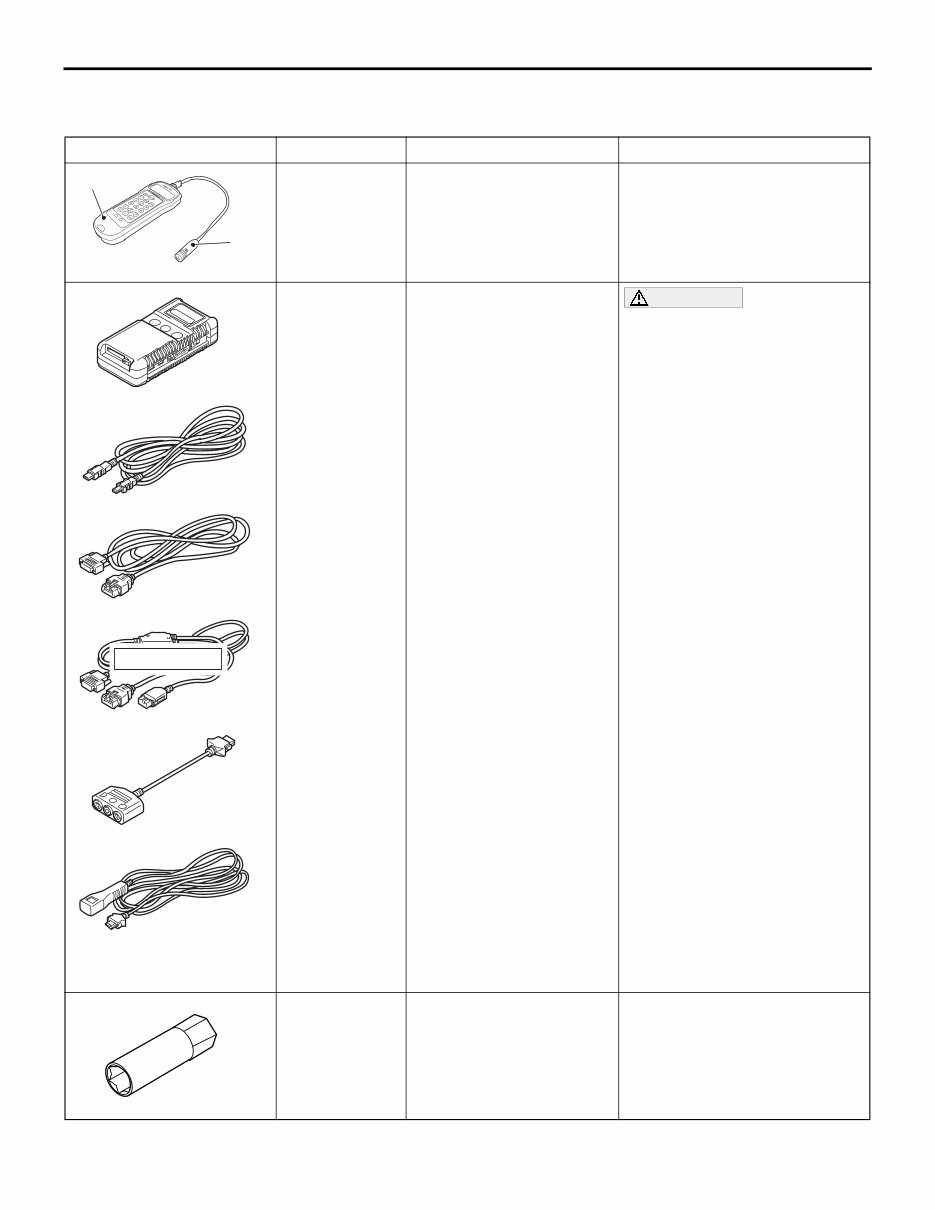
SPECIAL TOOLS ENGINE MECHANICAL 11A-4 SPECIAL TOOLS M1111000602799 Tool Number Name Use B992080 a b MB992080 a: MB992081 b: MB992082 Belt tension meter set a: Belt tension meter b: Microphone assembly Drive belt tension check MB991910 MB991826 MB991955 MB991911 MB991824 MB991827 MB991825 a b c d e f DO NOT USE MB991955 a: MB991824 b: MB991827 c: MB991910 d: MB991911 e: MB991825 f: MB991826 M.U.T.-III sub assembly a: Vehicle communication interface (V.C.I.) b: M.U.T.-III USB cable c: M.U.T.-III main harness A (Vehicles with CAN communication system) d: M.U.T.-III main harness B (Vehicles without CAN communication system) e: M.U.T.-III adapter harness f: M.U.T.-III trigger harness CAUTION For vehicles with CAN communication, use M.U.T.-III main harness A to send simulated vehicle speed. If you connect M.U.T.-III main harness B instead, the CAN communication does not function correctly. • Checking the idle speed • Erasing diagnosis code MB992046 MB992046 Valve adjusting socket Adjustment of valve clearance
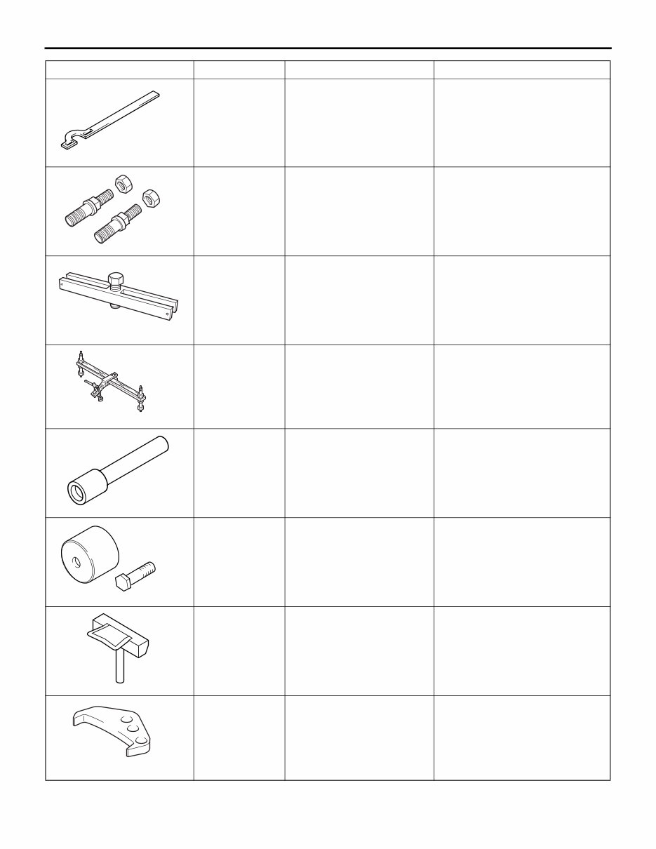
MB991800 SPECIAL TOOLS ENGINE MECHANICAL 11A-5 MB991800 Pulley holder Holding the crankshaft pulley B992100 MB992100 Crank pulley holder • Holding the crankshaft pulley • Crankshaft pulley removal B992099 MB992099 Crank pulley puller Crankshaft pulley removal MD998772 MD998772 Valve spring compressor Compressing valve spring MB991999 Valve stem seal installer Valve stem seal installation D998713 MD998713 Camshaft oil seal installer Camshaft oil seal installation D998727 MD998727 Oil pan FIPG cutter Oil pan removal MB991883 MB991883 Flywheel stopper • Supporting the flywheel assembly <M/T> • Supporting the inertia ring assembly <A/T> Tool Number Name Use
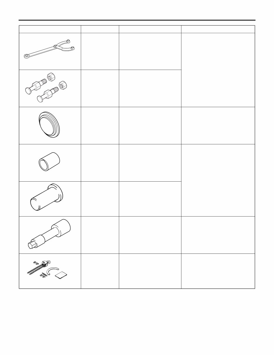
B990767 SPECIAL TOOLS ENGINE MECHANICAL 11A-6 MB990767 Front hub and flange yoke holder Holding the camshaft sprocket D998719 MD998719 Pin MB992147 Oil seal installer Crankshaft rear oil seal installation D998383 MD998383 Crankshaft front oil seal guide Crankshaft front oil seal installation D998382 MD998382 Crankshaft front oil seal installer MD998051 Cylinder head bolt wrench Removal and installation of cylinder head bolt B991683 MB991683 Sling chain set Removal and installation of engine assembly Tool Number Name Use
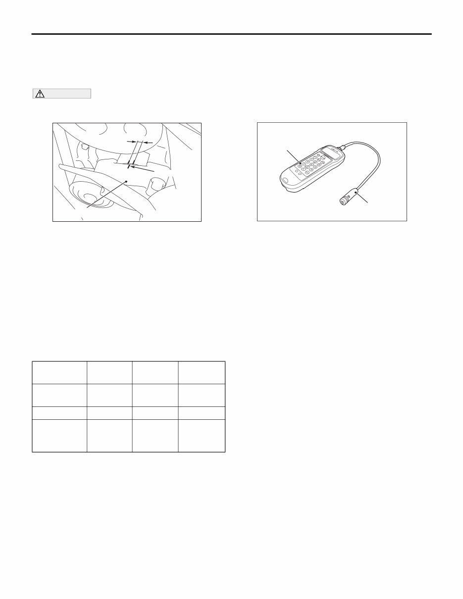
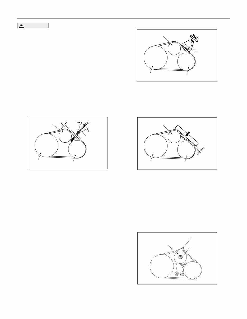
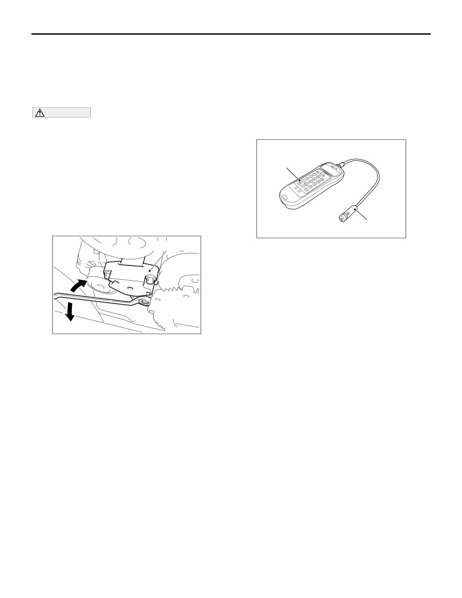
ON-VEHICLE SERVICE ENGINE MECHANICAL 11A-7 ON-VEHICLE SERVICE ALTERNATOR AND POWER STEERING OIL PUMP DRIVE BELT TENSION CHECK M1111001200033 CAUTION Check the drive belt tension after turning the crankshaft clockwise one turn or more. AC501803AB Indicator mark A Auto tensioner 1. Make sure that the indicator mark is within the area marked with A in the illustration. 2. If the mark is out of the area, replace the drive belt. (Refer to P.11A-17). NOTE: The drive belt tension check is not neces- sary as auto tensioner is adopted. A/C COMPRESSOR DRIVE BELT TENSION CHECK AND ADJUSTMENT M1111001000363 Check the drive belt tension by the following proce- dures. STANDARD VALUE: Item When checked When adjusted When replaced Vibration frequency Hz 222.5 − 251.0 222.5 − 251.0 259.8 − 300.0 Tension N 363 − 462 363 − 462 495 − 660 Deflection mm (Reference) 6.8 − 8.0 6.8 − 8.0 5.1 − 6.4 WHEN THE VIBRATION FREQUENCY IS MEASURED (SPECIAL TOOL MB992080 IS USED): RECOMMENDATION NOTE: The vibration frequency measuring method is recommended for check and adjustment of the drive belt tension. AC507219 AB MB992082 MB992081 Belt tension meter set (MB992080) 1. Connect special tool microphone assembly (MB992082) to special tool belt tension meter (MB992081) of special tool belt tension meter set (MB992080). 2. Press the "POWER" button to turn on the power supply. 3. Press the numeral key of "1" and check that "No.1" appears on the upper left of the display. NOTE: This operation is to temporarily set the preset data such as the belt specifications, because if the measurement is taken without input of the belt specifications, conversion to tension value (N) cannot be made, resulting in judgement of error. 4. Press "Hz" button twice to change the display to the frequency display (Hz).
ON-VEHICLE SERVICE ENGINE MECHANICAL 11A-8 CAUTION • The temperature of the surface of the belt should be as close to normal temperature as possible. • Do not let any contaminants such as water or oil get onto the microphone. • If strong gusts of wind blow against the microphone or if there are any loud sources of noise nearby, the values measured by the microphone may not correspond to actual values. • If the microphone is touching the belt while the measurement is being made, the values measured by the microphone may not corre- spond to actual values. • Do not take the measurement while the vehi- cle's engine is running. AC903689 15˚ 15˚ MB992080 (Microphone) 10 – 15 mm AB Tensioner pulley Crankshaft pulley A/C compressor pulley 5. Hold special tool MB992080 to the middle of the belt between the pulleys (at the place indicated by arrow) where it does not contact the belt (approximately 10 − 15 mm away from the rear surface of the belt) so that it is perpendicular to the belt (within an angle of ± 15 °). 6. Press the "MEASURE" button. 7. Gently tap the middle of the belt between the pulleys (the place indicated by the arrow) with your finger as shown in the illustration, and check that the vibration frequency of the belt is within the standard value. NOTE: To take the measurement repeatedly, fillip the belt again. WHEN USING THE TENSION GAUGE AC506003AB Tensioner pulley Crankshaft pulley A/C compressor pulley Tension gauge Use a belt tension gauge in the middle of the belt between the pulleys shown in the figure (at the place indicated by the arrow) to check that the belt tension is within the standard value. BELT DEFLECTION CHECK AC506004AB Tensioner pulley Crankshaft pulley A/C compressor pulley Approximately 100N Deflection Apply approximately 100 N of pressure against the location between the pulleys shown by the arrow in the illustration and then measure the deflection. When the belt tension is adjusted by measuring the belt deflection, adjust it with a tool for vibration fre- quency measurement or tension measurement after- ward. BELT TENSION ADJUSTMENT If not within the standard value, adjust the belt ten- sion by the following procedure. AC505988 AB Adjusting bolt Locking nut Tensioner pulley 1. Loosen the locking nut of the tensioner pulley.
ON-VEHICLE SERVICE ENGINE MECHANICAL 11A-9 2. Use the adjusting bolt to adjust the belt tension. The tension will increase when turning the adjusting bolt clockwise, and decrease when turning anti-clockwise. 3. Tighten the locking nut. 4. Tighten the adjusting bolt. CAUTION When checking the belt tension, turn the crank- shaft clockwise one turn or more. 5. Check the belt tension, and readjust if necessary. AUTO-TENSIONER CHECK M1111003003216 OPERATION CHECK 1. Turn off the engine from the idle state then check to see that the drive belt is not protruding from the pulley width of the auto tensioner. 2. Remove the drive belt (Refer to P.11A-17). AC501804 AC507703 Auto tensioner AB 3. Install the tool to the auto tensioner, and check that no binding is present by turning the auto tensioner in the left and right directions. 4. If there are any problems in the procedure 1 or 3, replace the auto tensioner (Refer to P.11A-43). 5. Install the drive belt (Refer to P.11A-17). FUNCTION CHECK You can verify if the auto tensioner is defective or not by checking the drive belt tension. When the vibration frequency is measured (Special tool MB992080 is used): Recommendation 1. Check the drive belt tension (Refer to P.11A-7). 2. Measure the drive belt tension vibration frequency by the following procedures: AC507219 AB MB992082 MB992081 Belt tension meter set (MB992080) (1) Connect special tool microphone assembly (MB992082) to special tool belt tension meter (MB992081) of special tool belt tension meter set (MB992080). (2) Press the "POWER" button to turn on the power supply. (3) Press the numeral key of "1" and check that "No.1" appears on the upper left of the display. NOTE: This operation is to temporarily set the preset data such as the belt specifications, because if the measurement is taken without input of the belt specifications, conversion to tension value (N) cannot be made, resulting in judgement of error. (4) Press "Hz" button twice to change the display to the frequency display (Hz).
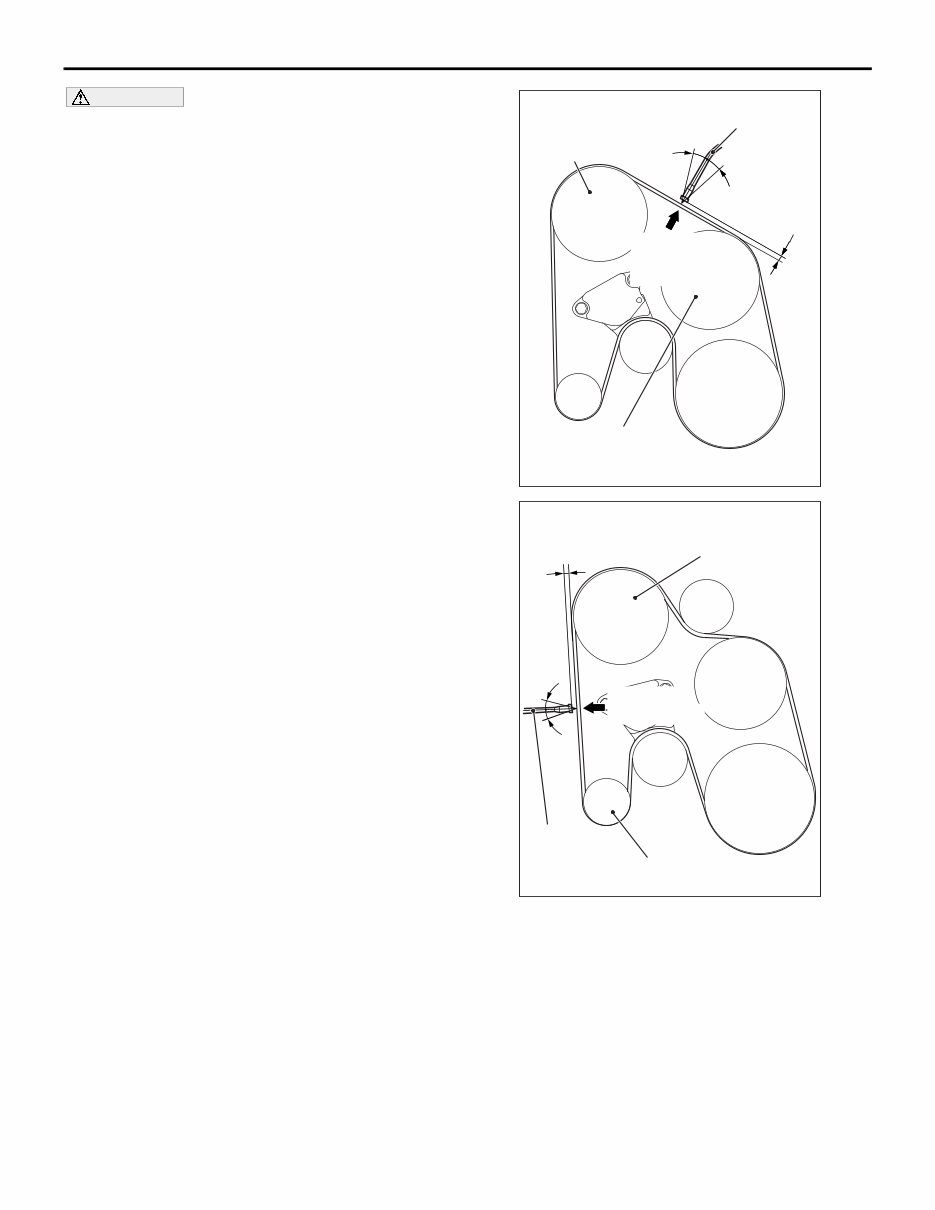
ON-VEHICLE SERVICE ENGINE MECHANICAL 11A-10 CAUTION • The temperature of the surface of the belt should be as close to normal temperature as possible. • Do not allow any contaminants such as water or oil to get onto the microphone. • If strong gusts of wind blow against the microphone or if there are any loud sources of noise nearby, the values measured by the microphone may not correspond to actual values. • If the microphone is touching the belt while the measurement is being made, the values measured by the microphone may not corre- spond to actual values. • Do not take the measurement while the vehi- cle's engine is running. AC805802 AF 15˚ 15˚ 10 – 15 mm Power steering oil pump pulley MB992080 (Microphone) <Except Euro5> Gentry tap with your finger Water pump pulley AC805654 AG 15˚ 15˚ 10 – 15 mm Alternator pulley Power steering oil pump pulley MB992080 (Microphone) Gentry tap with your finger <Euro5> (5) Hold special tool MB992080 to the middle of the belt between the pulleys (at the place indicated by arrow) where it does not contact the belt (approximately 10 − 15 mm away from the rear surface of the belt) so that it is perpendicular to the belt (within an angle of ± 15 °). (6) Press the "MEASURE" button.
This is the Official Service and Repair Manual for the 2006-2008 Mitsubishi Montero/Pajero/Shogun. It covers all models and engines within this range, providing detailed instructions for repair, maintenance, rebuilding, and refurbishing. The manual includes diagnostic procedures, repair instructions, and troubleshooting techniques enhanced by illustrations, diagrams, wiring schematics, and detailed specifications. All pages are printable, ensuring easy reference in the garage or workshop. This cost-effective manual is ideal for both DIY enthusiasts and experienced mechanics.
The manual covers an extensive range of service and repair topics, including:
Engine overhaul and performance testing
Brake system diagnostics and servicing
Sunroof and electrical system troubleshooting
Timing belt replacement and maintenance procedures
Trouble code analysis and resolution
Wiring diagrams and vacuum schematic layouts
Front end and alignment procedures
Suspension repairs and adjustments
Transmission removal, installation, and in-car servicing
Air conditioning service and diagnostics
Computer diagnostic codes and firing orders
Detailed model specifications and factory maintenance schedules
Serpentine belt routings and complete torque specifications
U-joint and CV-joint service procedures
Exploded diagrams, illustrations, and repair procedures
Model Specification: 2006-2008 Mitsubishi Montero/Pajero/Shogun Language: English File Format: PDF Total Pages: More than 5000 pages Requirements: Adobe Reader & Windows Zoom In/Out: Yes Instant Delivery: Yes Specifications: Fully Printable & Bookmarked Compatible: All Versions of Windows & Mac
This comprehensive manual is complete and intact, with no missing or corrupt pages or sections. It is bookmarked and searchable for easy navigation. Detailed illustrations, exploded diagrams, drawings, and photographs are included to clearly guide users through each service repair procedure. The manual is viewable on any computer, allowing for zooming and printing. Instant delivery eliminates shipping costs and waiting time, with immediate access provided upon payment via a secure processor. Major credit/debit cards and PayPal are accepted.
By utilizing this manual, individuals can perform repairs themselves and save money.
Recently Viewed
5,521,897Happy Clients
2,594,462eManuals
1,120,453Trusted Sellers
15Years in Business
Price:
Actual Price:
2006-2008 Mitsubishi Montero/Pajero/Shogun Service & Repair Manual