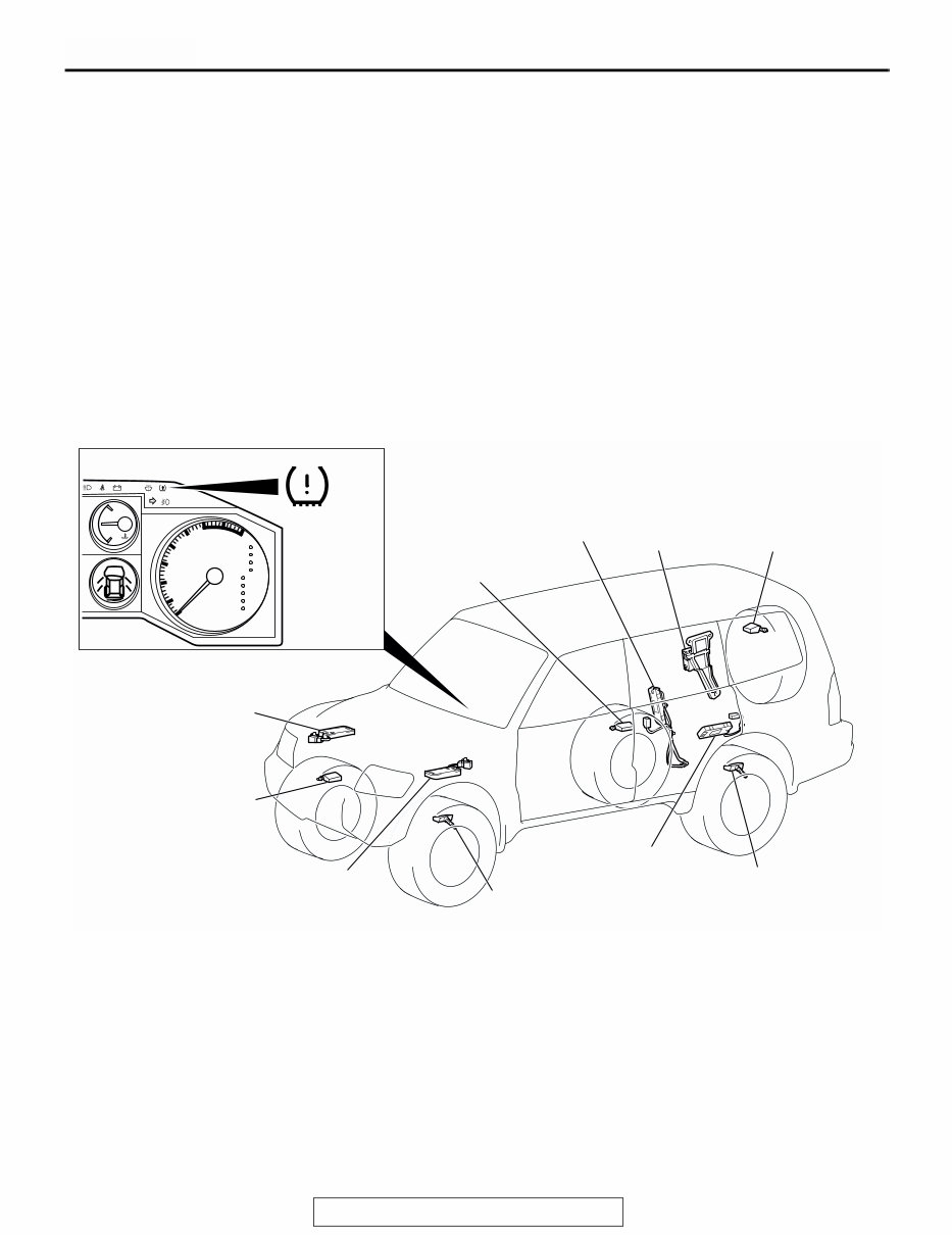
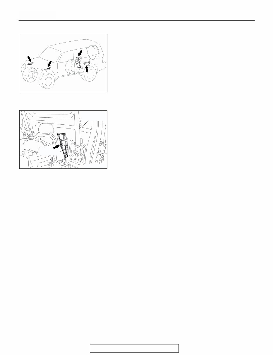
GENERAL DESCRIPTION TSB Revision WHEEL AND TIRE 31-2 GENERAL DESCRIPTION M1311000100093 FEATURE • Warns driver of low tire pressure by illuminating the TPMS warning light on the combination meter • Warns driver of TPMS problems by flashing the TPMS warning light on the combination meter TIRE PRESSURE MONITORING SYSTEM (TPMS) The Tire Pressure Monitoring System (TPMS) con- sists of five TPMS transmitters (tire pressure sensors and roll switches) installed in all tires, four TPMS antennas installed inside the wheel houses, a TPMS receiver installed inside the lower quarter trim (RH), and a TPMS warning light on the combination meter. Each TPMS antenna receives radio frequency signal output from the TPMS transmitter, the TPMS receiver interprets the signals and detects abnormal- ity of tire pressure and/or the system, and the TPMS warning light illuminates or flashes to alert. CONSTRUCTION DIAGRAM AC307575 AC205999 H C AT TEMP SRS P R N D 5 4 3 2 1 x1000r/min 2 3 4 5 6 7 8 1 0 AC307585 TPMS ANTENNA (FRONT: RH) TPMS RECEIVER TPMS TRANSMITTER (FRONT: RH) TPMS WARNING LIGHT TPMS ANTENNA (FRONT: LH) TPMS ANTENNA (REAR: RH) TPMS ANTENNA (REAR: LH) TPMS TRANSMITTER (FRONT: LH) TPMS TRANSMITTER (REAR: RH) TPMS TRANSMITTER (REAR: LH) TPMS TRANSMITTER (SPARE) AB NOTE: Each TPMS transmitter has a pressure sensor and roll switch.
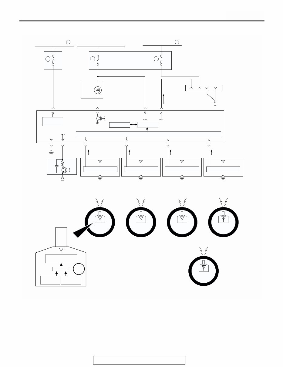
GENERAL DESCRIPTION TSB Revision WHEEL AND TIRE 31-3 CIRCUIT DIAGRAM • The TPMS receiver processes input signals from each TPMS transmitter as well as vehicle speed signals from the vehicle speed sensor. When the road tire pressure is low, it sends a warning sig- nal causing the TPMS warning light to be illumi- nated. When the TPMS has problems, it sends a warning signal causing the TPMS warning light to be flashed. • The TPMS transmitter includes a roll switch that senses tire rotation. The TPMS receiver can determine which tires are rotating (road tire) and stationary (spare tire). • For 3 seconds after the ignition switch is turned to the "ON" position, the TPMS receiver illuminates the TPMS warning light to check any breaks in the TPMS warning light circuit. AC307586 RELAY BOX JUNCTION BLOCK COMBINATION METER TPMS RECEIVER DATA LINK CONNECTOR FRONT TIRE (LH) FRONT TIRE (RH) REAR TIRE (LH) REAR TIRE (RH) IGNITION SWITCH (IG1) FUSIBLE LINK TPMS POWER SUPPLY GND RECEIVING CIRCUIT EEPROM VEHICLE SPEED SENSOR CPU TPMS TRANSMITTER TPMS ANTENNA (FRONT: LH) CONTROL CIRCUIT TPMS ANTENNA (FRONT: RH) CONTROL CIRCUIT TPMS ANTENNA (REAR: LH) CONTROL CIRCUIT CPU TRANSMISSION CIRCUIT SPARE TIRE 18 15A 6 10A 10 20A 2 FUSIBLE LINK 1 AB ANTENNA TPMS ANTENNA (REAR: RH) CONTROL CIRCUIT PRESSURE SENSOR ROLL SWITCH BATTERY
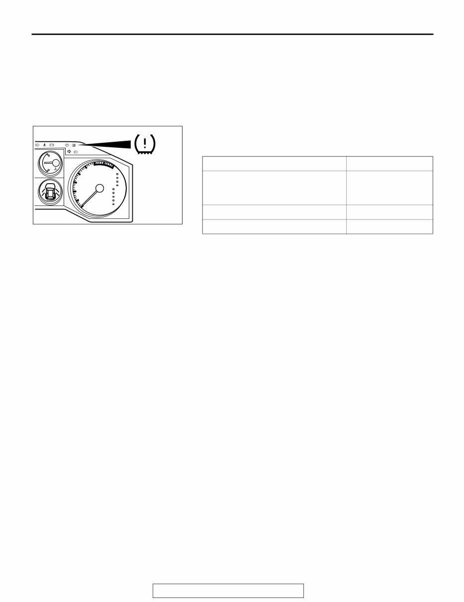
GENERAL DESCRIPTION TSB Revision WHEEL AND TIRE 31-4 • By connecting the scan tool to the data link con- nector, data stored in the TPMS receiver (data of tire pressure and tire pressure sensor ID, the alarm status and warning history, etc.) can be dis- played and the tire pressure sensor ID can be registered. TPMS WARNING LIGHT The TPMS warning light on the combination meter illuminates or flashes to alert the driver when signals are entered from the TPMS receiver. NOTE: . • Immediately after the tire pressure sensor ID has been rec- ognized, the TPMS receiver cannot recognize the road tires until the vehicle is driven for some time. Therefore, if the spare tire pressure is low, the TPMS warning light will illumi- nate. • The tire pressure monitoring is not applicable for the spare tire. Therefore, if the low-pressure road tire is used as a spare tire, the TPMS warning light will go out as soon as the TPMS receiver recognizes that. CIRCUMSTANCE WARNING LIGHT For 3 seconds after the ignition switch is turned to the "ON" position (warning light circuit self-check) Illuminates TPMS problems Flashes Low tire pressure of any road tire Illuminates AC205999 H C AT TEMP SRS P R N D 5 4 3 2 1 x1000r/min 2 3 4 5 6 7 8 1 0 AC307585
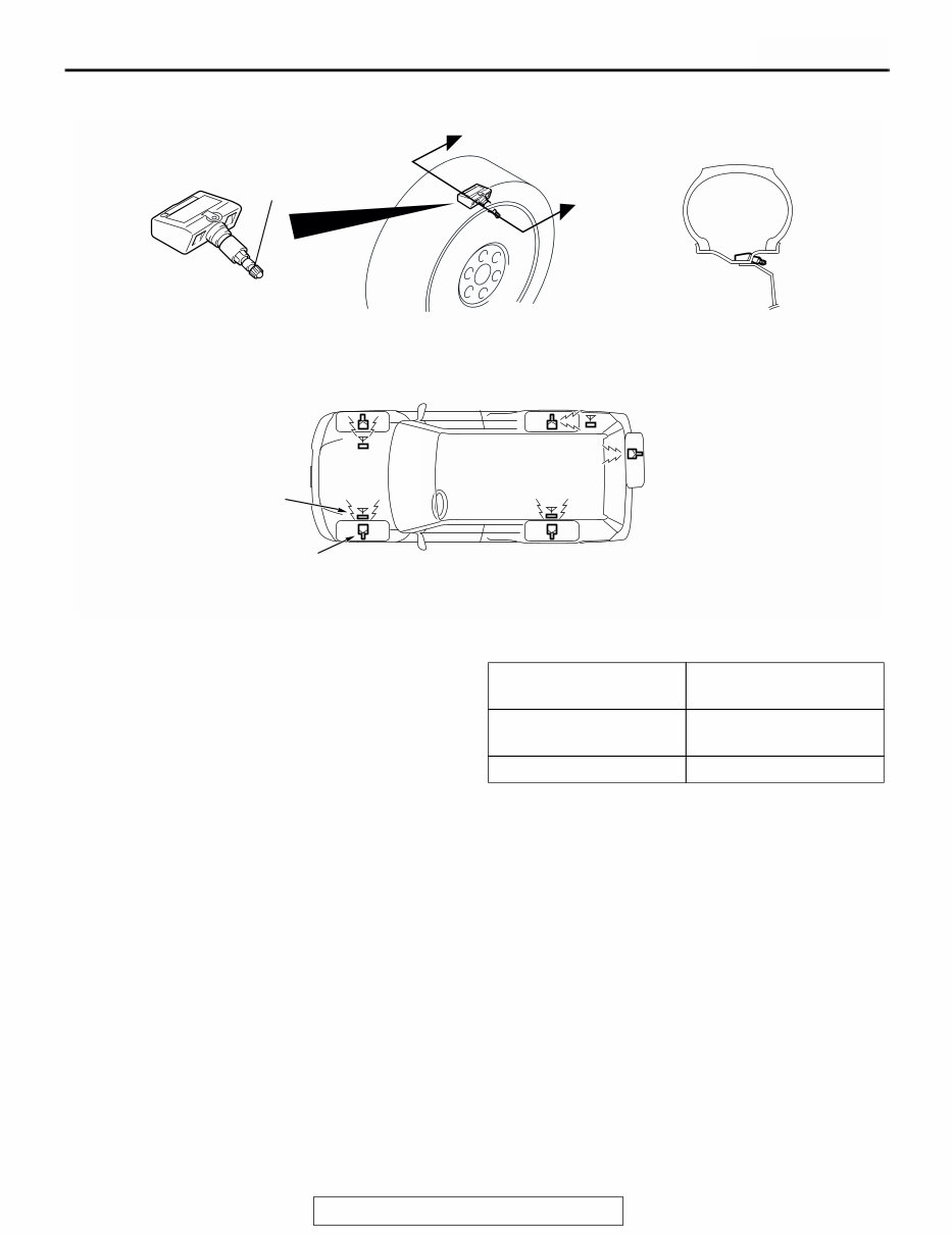
GENERAL DESCRIPTION TSB Revision WHEEL AND TIRE 31-5 TPMS TRANSMITTER (TIRE PRESSURE SENSOR) The TPMS transmitter combines the valve and tire pressure sensor in a single unit. The TPMS transmit- ters are mounted inside the tires (including the spare tire). The TPMS transmitter measures tire pressure directly with its tire pressure sensor and sends radio frequency signals to the antenna inside the wheel house. The TPMS transmitter includes a roll switch that senses tire rotation. The TPMS receiver can determine which tires are rotating (road tire) and sta- tionary (spare tire). NOTE: Use only genuine wheels. The use of non-genuine wheels may cause the improper instal- lation of the TPMS transmitters, possibly resulting in air leakage and damage to the TPMS transmitter. . TIRE PRESSURE SAMPLING TIMING Tire pressure sampling: Once every 30 sec- onds . DATA TRANSMISSION TIMING If a sampled pressure varies by ±10 kPa (1.5psi) from the last transmitted pressure value, an additional transmission will occur. NOTE: Vehicle moving = vehicle speed: approxi- mately 30 km/h (19 mph) or more <roll switch: ON> NOTE: Service period = First 15 minutes after vehi- cle stops <roll switch: OFF> NOTE: Vehicle stationary = Situations except vehicle moving and service period <roll switch: OFF> AC307594 AC307583 AC307584 AB VALVE TPMS TRANSMITTER (TIRE PRESSURE SENSOR) A SECTION A - A A TPMS ANTENNA TPMS TRANSMITTER VEHICLE STATUS TRANSMISSION TIMING At vehicle moving and service period once every 1 minute At vehicle stationary once every 1 hour
GENERAL DESCRIPTION TSB Revision WHEEL AND TIRE 31-6 TPMS ANTENNAS The TPMS for Montero has four TPMS antennas. Each TPMS antenna is installed inside the wheel house. The TPMS antenna receives radio frequency signal from the TPMS trans- mitter and sends it to the TPMS receiver via feeder cable. TPMS RECEIVER 1. The TPMS receiver is installed at the inner quarter panel (RH), and monitors the tire pressure of road tires except spare tire. The TPMS receiver receives a signal from a TPMS transmitter every one minute if the TPMS transmitter is revolving (i.e. it is embedded in road wheel tire). NOTE: The TPMS receiver detects automatically that the tire is "spare" tire (not on the road). Then the receiver ignores the spare tire. The spare tire transmitter sends a signal once every hour if it stationary (i.e. it is embedded in spare tire). 2. When the ignition switch is at the "LOCK" (OFF) position, The TPMS receiver should operate intermittently (supplies power to receiving circuit intermittently). 3. The TPMS receiver has the following functions: • SCAN TOOL (MUT-III) communication functions • Warning function . SCAN TOOL (MUT-III) COMMUNICATION FUNCTIONS The following functions can be performed by con- necting the scan tool to the data link connector and starting the MUT-III. • Diagnostic trouble code reading function (for DTC chart, refer to P.31-19.) • Service data reading function (for service data list, refer to P.31-84.) • Actuator testing function (for test item, refer to P.31-85.) • Tire pressure sensor ID registration function <TPMS special function (for data list, refer to P.31-85).> NOTE: If the TPMS transmitters or TPMS receiver are replaced, the tire pressure sensor ID for all tires must be registered in the TPMS receiver. • Tire pressure sensor check function <TPMS spe- cial function (for data list, refer to P.31-85).> The pressure sensor data can be displayed by using a magnet to send the signal from each TPMS transmitter. • Tire pressure sensor ID check function <TPMS special function (for data list, refer to P.31-85).> Each tire pressure sensor ID currently registered in the TPMS receiver is displayed. . WARNING FUNCTIONS The TPMS receiver determines the need for a warn- ing based on the input data from the TPMS antennas and the vehicle speed sensor signal from the vehicle speed sensor. When the TPMS receiver sends a warning signal (a TPMS warning light bulb check sig- nal, a tire pressure warning signal, or a TPMS warn- ing signal), the TPMS warning light on the combination meter is illuminated or flashed. Three seconds after the ignition switch is turned to the "ON" position, or if the problem is corrected, the TPMS warning light goes off. AC307347 AB TPMS ANTENNAS AC307592 AB TPMS RECEIVER THIRD SEAT BELT (RH)
GENERAL DESCRIPTION TSB Revision WHEEL AND TIRE 31-7 TPMS warning light bulb check signal <TPMS warning light: illuminated> • The TPMS receiver turns on the TPMS warning light for 3 seconds when the ignition switch is turned to the "ON" position. The driver can judge disconnection of the TPMS warning light if it does not come on. • After the 3 seconds illumination, the TPMS receiver turns off the TPMS warning light for 0.2 second, so that the mechanic can detect the fail- ure of the illumination circuit through the TPMS warning light ON in the tire pressure warning state. Tire pressure warning signal <TPMS warning light: illuminated> • When a received tire pressure sensor ID matches the registered tire pressure sensor ID in the TPMS receiver, and the received tire pressure value is lower than the threshold value, then the TPMS receiver considers it in the tire pressure warning state and outputs the warning and sets the diagnostic trouble code. • Also while the vehicle is parked (ignition switch: "LOCK" (OFF) position), the TPMS receiver mon- itors tire pressure. And it outputs the warning when the ignition switch is turned to the "ON" position, if the tire pressure is in the warning state. • When the received tire pressure sensor ID matches with the registered tire pressure sensor ID in the TPMS receiver, and the tire pressure value received is higher than the threshold value, the TPMS receiver clears the tire pressure warn- ing against the tire pressure sensor ID. If the tire warning is cleared for all the tires including the spare tire, the TPMS warning light will go out. TIRE PRESSURE THRESHOLD VALUES TPMS warning signal (EEPROM abnormality) <TPMS warning light: flashes> • The TPMS receiver checks EEPROM. When information in the EEPROM is considered abnor- mal due to tire pressure sensor ID deterioration, etc., the TPMS receiver outputs the warning and sets a diagnostic trouble code. TPMS warning signal (reception failure) <TPMS warning light: flashes> • The TPMS receiver outputs the warning signal and sets a diagnostic trouble code when the sig- nals matched with the registered tire pressure sensor IDs in the TPMS receiver were not received. • When the TPMS receiver receives normal signals for the tire pressure sensor ID that had reception failure problems, the TPMS receiver clears the warning. TPMS warning signal (TPMS transmitter battery voltage abnormality) <TPMS warning light: flashes> • The TPMS receiver is considered to be in system warning state due to TPMS transmitter low bat- tery voltage against its tire pressure sensor ID. The receiver outputs the warning signal and sets a diagnostic trouble code under the following conditions. The received tire pressure sensor ID matches the registered tire pressure sensor ID in the TPMS receiver, and function code Low Bat- tery is received consecutively. • The TPMS receiver clears the warning state against its tire pressure sensor ID under the fol- lowing conditions. The received tire pressure sensor ID matches with the registered tire pres- sure sensor ID in the TPMS receiver, and Normal Pressure function code is received consecu- tively. TPMS warning signal (vehicle speed signal abnormality) <TPMS warning light: flashes> • When vehicle speed input is always less than 5 km/h (3 mph), the TPMS receiver judges the sys- tem to be vehicle speed signal abnormality warn- ing and outputs the warning and set a diagnostic trouble code. • The warning will be cleared when vehicle speed signal is over 5 km/h (3 mph) for over 1 second with the ignition switch in the "ON" position. TPMS warning signal (Transmitter OFF mode) <TPMS warning light: flashes> • Transmitting signal of the TPMS transmitter should be stopped during transportation to dealer because it will break Japanese radio wave regu- lation. • OFF mode is canceled at dealer. So, output warning and set DTC 17 (Transmitter OFF Mode, ALL Tire) during transmitter OFF mode for reminding cancel of OFF mode. • When the TPMS receiver receives the signals from all registered tire pressure sensor, the TPMS receiver clears the warning. ITEM TIRE PRESSURE kPa (psi) Standard pressure at cold (reference) 200 (29) Alarm ON pressure 158 (23) or less Alarm OFF pressure 174 (25) or more
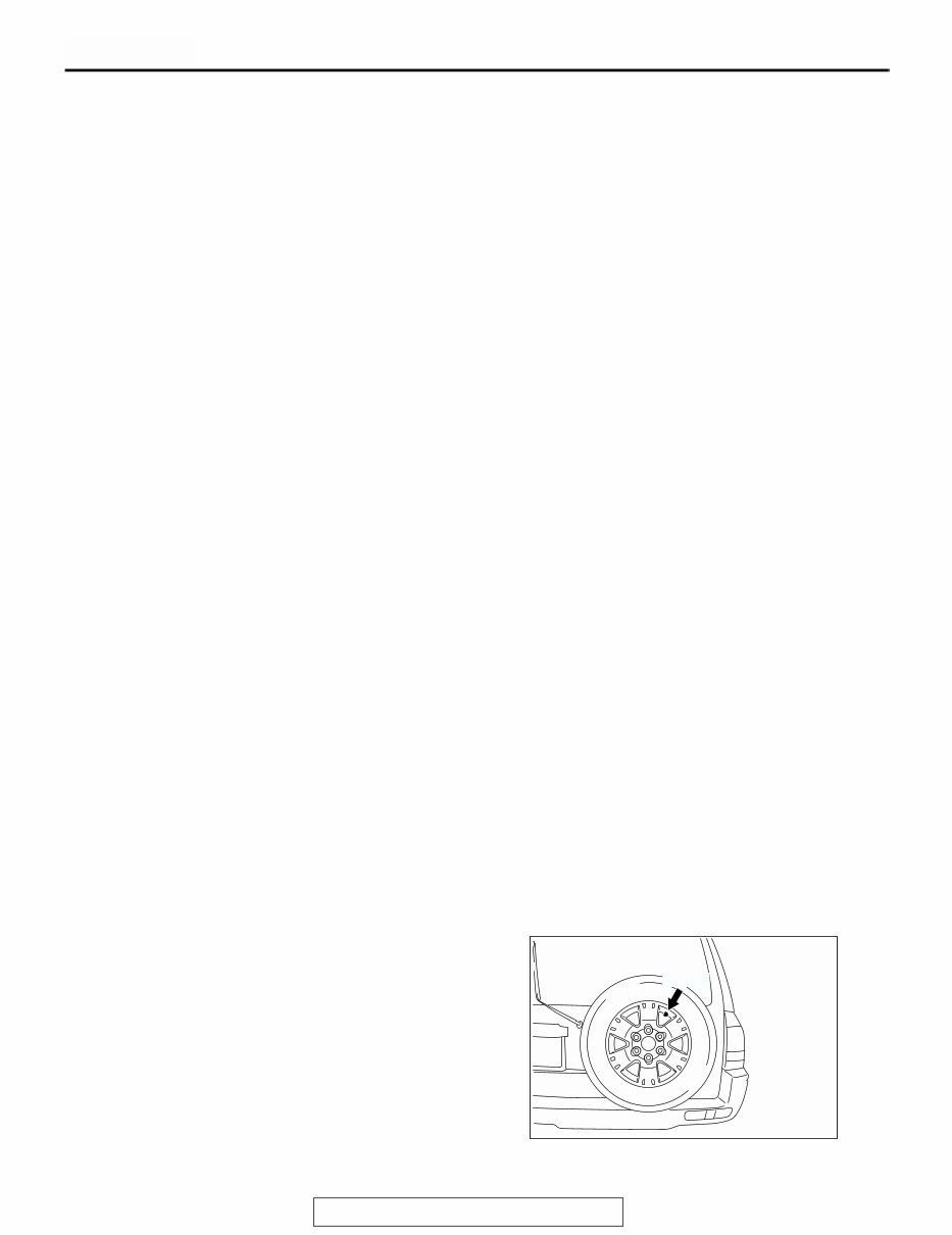
TIRE PRESSURE MONITORING SYSTEM (TPMS) SERVICE PRECAUTIONS TSB Revision WHEEL AND TIRE 31-8 TPMS OPERATIONAL CHARACTERISTICS • The TPMS receiver monitors the tire pressure of road tires except spare tire. • The TPMS transmitter includes a roll switch that senses tire rotation. The TPMS receiver can determine which tires are rotating (road tire) and stationary (spare tire). • The recommended cold tire pressure at normal condition for Montero is 200 kPa (29 psi). The TPMS warning light will turn ON and DTC 23/27/32/36/41/ will be stored in memory when the air pressure in any road tire is below 158 kPa (23.0 psi). • The TPMS warning light will turn OFF and the DTC 23/27/32/36/41 in memory will be eliminated when the tire pressure is increased to at least 174 kPa (25.25 psi). • Customers may experience what appears to be an "intermittent" tire pressure warning light because the air pressure in the tires normally fluctuates under various operating conditions: • In cold weather, tire pressure will become lower due to the ambient temperature, and the TPMS warning light will turn ON if tire pressure drops below 158 kPa (23.0 psi). The tire pressure will increase after driving (tires warm up), and the TPMS warning light will turn OFF. Regardless of the ambient temperature, set the tire pressure to 200 kPa (29 psi) with the tires cold [vehicle has been parked for at least three hours or driven less than 1.6 kilometers (one mile) after having been parked for three hours]. NOTE: Tire pressure changes at slightly less than 6.9 kPa (1 psi) per 5.5°C (10°F) of ambi- ent temperature change. For example, climates with seasonal temper- atures that vary from 32°C (90°F) in the sum- mer to -12°C (10°F) in the winter have a 44 degree Celsius (80 degrees Fahrenheit) tem- perature change. This can result in an approximate 55 kPa (8 psi) change in tire pressure. In this example: • If the tire pressure was set when the ambi- ent temperature was 32°C (90°F) in the summer, it can be about 145 kPa (21 psi) on the coldest day in the winter. This will cause the TPMS warning light to turn on. • If the tire pressure was set when the ambi- ent temperature was -12°C (10°F) in the winter, it can be about 255 kPa (37 psi) on the hottest day of the summer. This will create a rougher ride. The important point is that customers should have their tire pressure seasonally adjusted. TIRE PRESSURE MONITORING SYSTEM (TPMS) SERVICE PRECAUTIONS M1311004300022 • Transmitting signal of the TPMS transmitter should be stopped during transportation to dealer because it will break Japanese radio wave regu- lation. • OFF mode is canceled at dealer. So, output warning and set DTC 17 during transmitter OFF mode for reminding cancel of OFF mode. • Do not use an aerosol puncture-repair spray. Such a spray could damage the tire pressure sensor (TPMS transmitter). • Whenever the TPMS transmitters and/or TPMS receiver are replaced with new ones, the tire pressure sensor IDs must be registered into the TPMS. • Install the spare tire as shown. If the spare tire valve (TPMS transmitter) is not positioned as shown, the roll switch, which is incorporated in the TPMS transmitter, may operate. In that case, the system may determine the spare tire as a road tire incorrectly. • The use of non-genuine wheels may cause the improper installation of the TPMS transmitters, possibly resulting in air leakage and damage to the TPMS transmitter. AC307590 AB VALVE
TIRE PRESSURE MONITORING SYSTEM (TPMS) SERVICE PRECAUTIONS TSB Revision WHEEL AND TIRE 31-9 • When the tire is removed from the wheel, a spe- cial procedure must be observed to avoid the TPMS transmitter damage. Refer to "TPMS transmitter Removal and Installation (P.31-97)". • The grommet at base of valve stem should be replaced with a new one every five years or when the tire is replaced. For the replacement proce- dure, refer to "TPMS transmitter Removal and Installation (P.31-97)". • After the TPMS transmitter is replaced and the tires are inflated, retighten the valve nut (TPMS transmitter mounting nut) to the specified torque, refer to "TPMS transmitter Removal and Installa- tion (P.31-97)". • Replace the TPMS transmitter when the TPMS transmitter battery is discharged. The battery cannot be removed from the TPMS transmitter. Nominal service life of the battery is 10 years or 160,000 km (100,000 miles). • If the valve core and valve cap are replaced, use a genuine replacement part. The valve core is similar to a conventional one, but nickel plating was applied to avoid electric corrosion. • TPMS may not work normally in the following cir- cumstances: • A wireless facility or device using the same frequency with the TPMS transmitter is near the vehicle. • Snow or ice is stuck inside the wheel houses and /or on the wheels. • The TPMS transmitters battery is discharged. • Wheels other than Mitsubishi genuine wheels are being used. • Wheels that are not fitted with TPMS transmit- ters are being used. • Wheels whose tire pressure sensor IDs are not registered by the vehicle are being used. NOTE: Tire inflation pressures vary with the ambient temperature. If the vehicle is subjected to large varia- tions in ambient temperature, the tire inflation pres- sures may be under-inflated (causing the TPMS warning light to come on) when the ambient temper- ature is relatively low. If the TPMS warning light comes on, adjust the tire inflation pressure. NOTE: If any of the road wheel tires do not contain a TPMS transmitter, and the customer continues driv- ing, the TPMS warning light will flash.
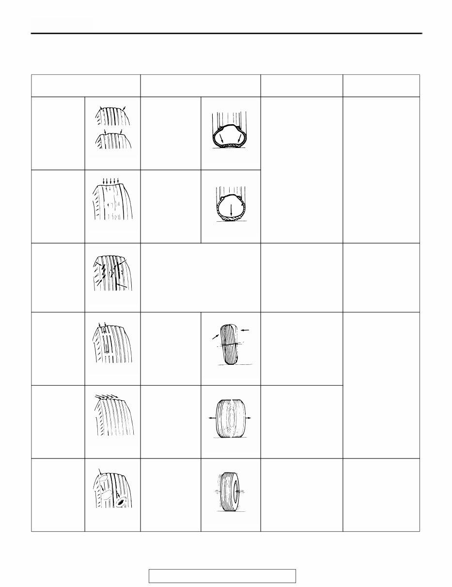
WHEEL AND TIRE DIAGNOSIS TSB Revision WHEEL AND TIRE 31-10 WHEEL AND TIRE DIAGNOSIS WHEEL AND TIRE DIAGNOSIS M1311000700415 SYMPTOM PROBABLE CAUSE REMEDY REFERENCE PAGE Rapid wear at shoulders Under-inflation or lack of rotation Adjust the tire pressure. For tire inflation pressure, refer to the label on the driver’s side center pillar. Rapid wear at center Over-inflation or lack of rotation Cracked treads Under-inflation Adjust the tire pressure. For tire inflation pressure, refer to the label on the driver’s side center pillar. Wear on one side Excessive camber Check the camber. Refer to GROUP 33A, On-vehicle service − Front wheel alignment check and adjustment P.33A-5. Feathered edge Incorrect toe-in Adjust the toe-in. Bald spots Unbalanced wheel Balance the wheels. − ACX00923AB ACX00924 AB ACX00925AB ACX00926AB ACX00927AB ACX00928 AB ACX00929 AB ACX00930AB ACX00931AB ACX00932AB ACX00933 AB
This is the 2004 Mitsubishi Montero Sport Service & Repair Manual. It contains comprehensive service and repair instructions used by mechanics worldwide and covers all major topics essential to maintaining your vehicle.
The manual provides detailed information on:
General Information
Engine Mechanical System
Engine Electrical System
Emission Control System
Fuel System
Clutch System
Manual Transaxle System
Automatic Transaxle System
Driveshaft and Axle
Suspension System
Steering System
Restraint and Brake System
Interior and Exterior Body
Body Electrical System
Heating, Ventilation, and Air Conditioning
Whether you are a professional mechanic or a DIY enthusiast with basic mechanical skills, this manual provides the same specifications and procedures available to an authorized dealer service department. It offers accurate, clear, and concise text along with illustrations that enable anyone with basic mechanical knowledge to safely and easily repair and maintain their vehicle.
Written by the manufacturers, this manual includes step-by-step repair procedures and easy-to-follow directions on required tools, helping you save significantly on repair bills while ensuring proper maintenance.
The manual is available in PDF format, making it compatible with all versions of Windows and Mac, and it can be viewed on various devices including PCs, Macs, phones, and e-readers for convenient access to individual pages when needed.
With its comprehensive coverage and vehicle-specific instructions, the 2004 Mitsubishi Montero Sport Service & Repair Manual is an essential resource for anyone looking to maintain or repair their vehicle.
Recently Viewed
5,521,897Happy Clients
2,594,462eManuals
1,120,453Trusted Sellers
15Years in Business
Price:
Actual Price:
2004 Mitsubishi Montero Sport Service & Repair Manual