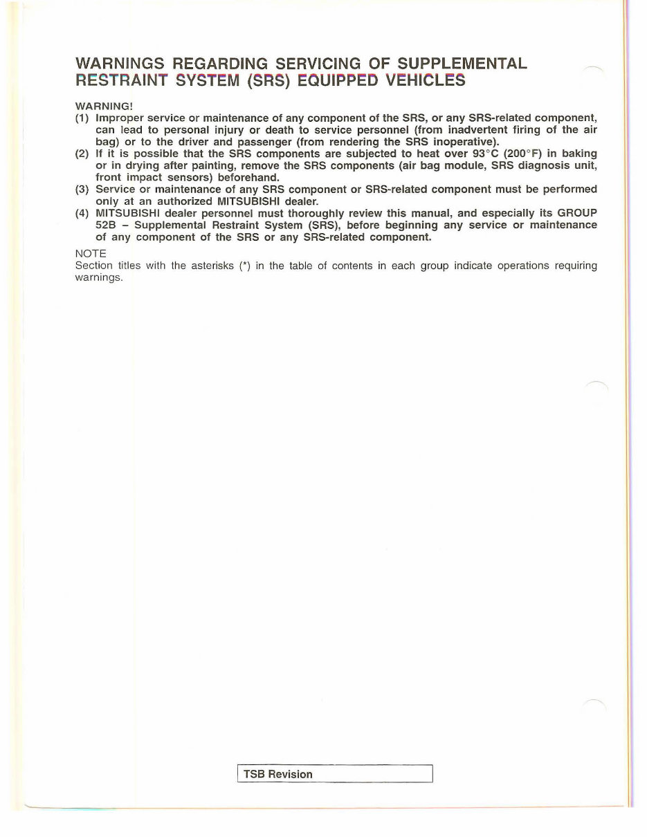
WARNINGS REGARDING SERVICING OF SUPPLEMENTAL RESTRAINT SYST EM (SRS) EQUIPPED VEHICLES WARNING! (1) Improper service or maintenance of any component of the SRS, or any SRS-related component , can lead to personal injury or death to service personnel (from inadvertent firing of the air bag) or to the driver and passenger (from rendering the SRS i noperative). (2) If it is possible that the SRS components are subjected to heat over 93°C (200°F) in baking or in drying after painti ng , remove the SRS components (air bag module, SRS diagnosis unit, front impact sensors) beforeha nd. (3) Service or ma i ntenance of any SRS component or SRS-related component must be performed only at an authorized MITSUBISHI dealer. (4) MITSUBISHI dealer personnel must thoroughly review this manual, and especially its GROUP 528 - Supplemental Restraint System (SRS), before beginn i ng any service or maintenance of any component of the SRS or any SRS-related component. NO TE Section titles with the aste ri sks (*) in the table of contents in each group indicate operations requiring wa rnings. j TSB Revision
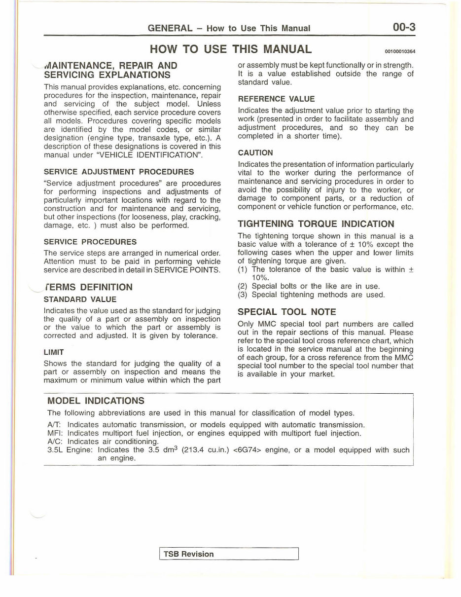
GENERAL - How to Use This Manual 00-3 HOW TO USE THIS MANUAL 00100010364 .lllAINTENANCE, REPAIR AND SERVICING EXPLANATIONS This manual provides explanations, etc. concerning procedures for the inspection, maintenance, repair and servicing of the subject model. Unless otherwise specified, each service procedure covers all models. Procedures covering specific models are identified by the model codes, or similar designation (engine type, transaxle type, etc.). A description of these designations is covered in this manual under "VEHICLE IDENTIFICATION". SERVICE ADJUSTMENT PROCEDURES "Service adjustment procedures" are procedures for performing inspections and adjustments of particularly important locations with regard to the construction and for maintenance and servicing, but other inspections (for looseness, play, cracking, damage, etc. ) must also be performed. SERVICE PROCEDURES The service steps are arranged in numerical order. Atten ti on must to be paid in performing vehicle service are described in detail in SERVICE POINTS. fERMS DEFINITION STANDARD VALUE Indicates th e value used as the standard for judging the quality of a part or assembly on inspection or the value to which the part or assembly is corrected and adjusted. It is given by tolerance. LIMIT Shows the standard for judging the quality of a part or assembly on inspection and means the maximum or minimum value within which the part MODEL INDICATIONS or assembly must be kept functionally or in strength. It is a value established outside the range of standard value. REFERENCE VALUE Indicates the adjustment value prior to starting the work (presented in order to facilitate assembly and adjustment procedures, and so they can be completed in a shorter time). CAUTION Indicates the presentation of information particularly vital to the worker during the performance of maintenance and servicing procedures in order to avoid the possibility of injury to the worker, or damage to component parts, or a reduction of component or vehicle function or performance, etc. TIGHTENING TORQUE INDICATION The tighteni ng torque shown in this manual is a basic value with a tolerance of ± 10% except the following cases when the upper and lower limits of tightening torque are given. (1) The tolerance of the basic value is within ± 10%. (2) Special bolts or the like are in use. (3) Special tightening methods are used. SPECIAL TOOL NOTE Only MMC special tool part numbers are ca ll ed out in the repair sections of this manual. Please refer to the special tool cross reference cha rt , which is located in the service manual at the beginning of each group, for a cross reference from the MMC special tool number to the special tool number that is available in your market. The following abbreviations are used in this manual for classification of model types. AfT: Indicates automatic transmission, or models equipped with automatic transmission. MFI: Indicates multiport fu el inj ection, or engines equipped with multiport fuel injection. AJC: Indicates air conditioning. 3.5L Engine: In dicates the 3.5 dm3 (213.4 cu.in.) <6G74> engine, or a model equipped with such an engine. I TSB Revision
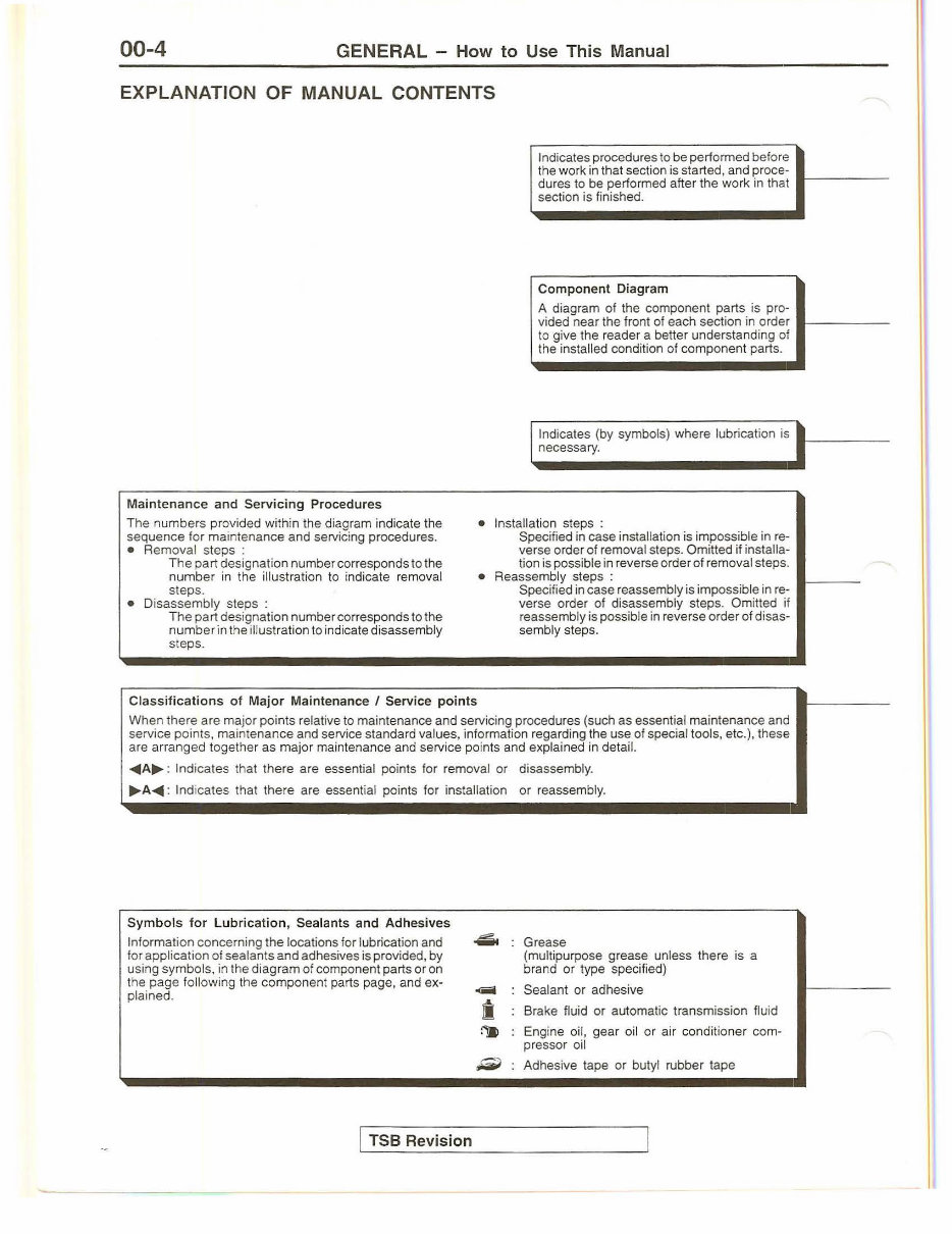
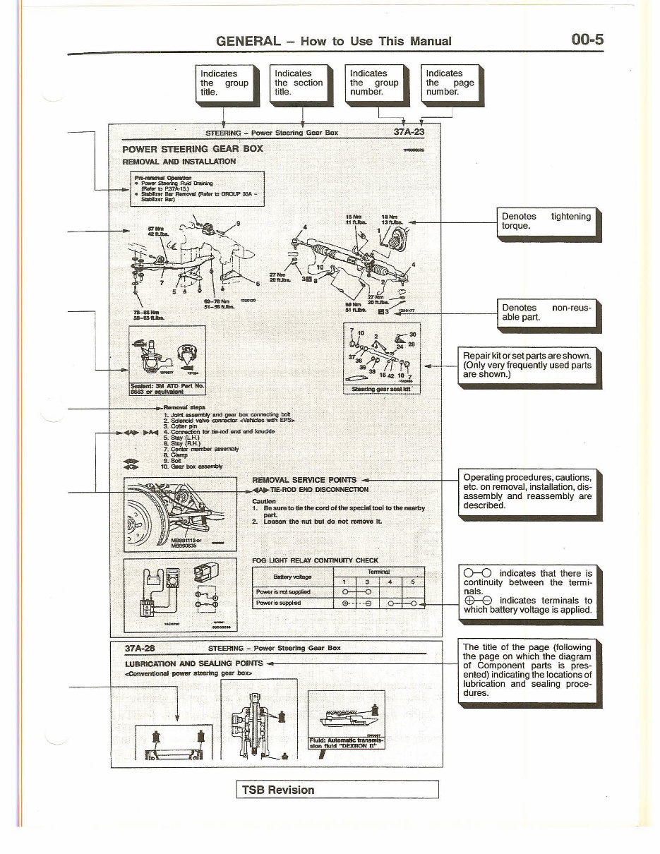
00-4 GENERAL - How to Use This Manual EXPLANATION OF MANUAL CONTENTS Mai ntenance and Servicin g Procedures The numbers provided within the diagram indicate the sequence for maintenance and servicing procedures. • Removal steps : The part designation number corresponds to the number in the il lustration to indicate removal steps. • Disassembly steps : The part designation number corresponds to the number in the illustration to indicate disassembly steps. Indicates procedures to be performed before the work in that section is started, and proce- dures to be performed after the work in that ------ - section is finished. Component Diagra m A diagram of the component parts is pro- vided near the front of each section in order ---- - -- to give the reader a better understanding of the installed condition of component part s. Indicates (by symbols) where l ubrication is ------ - necessary. • Installation steps : Specified in case installation is impossible in re- verse order of removal steps. Omitted if installa- tion is possible in reverse order of removal steps. • Reassembly steps : Specified in case reassembly is impossible in re- verse order of disassembly steps. Omitted if reassembly is possible in reverse order of disas- sembly steps. Classif icat io ns of Major Mai ntenance I Service points When there are major points relative to maintenance and servicing procedures (such as essential maintenance and service points. maintenance and service standard values, information regarding the use of special tools, etc.), these are arranged together as major maintenance and servi ce points and explained in detaiL ~A .... : Indicates that there are essential points for removal or disassembly . .... A~: Indicates that there are essential points for installation or reassembly. Symbols f or Lubri cati on, Sealants and Adh esives Information concerning the locations for lubrication and for application of sealants and adhesives is provided, by using symbols, in the diagram of component parts or on the page following the component parts page, and ex- pl ained. TSB Revision ----- ------------- 4iit Grease (multipurpose grease unless there is a brand or type specified) .- Sealant or adhesive Ji Brake fluid or automatic transmission fl ui d ~ Engine oil, gear oil or air conditioner com- pressor oil ,;;iii) Adhesive tape or butyl rubber tape
- - GENERAL - How to Use This Manual Indicates the group title. 1 Indicates the section title. 1 STEERING - Power Steering Gear Box ' Indicates the group number. Indicates the page number. J -- ---- 00-5 POWER STEERING GEAR BOX REMOVAL AND INSTALLATION - - tsNM ,,..., I Denotes tightening ~.r Q4r~~--~ 1 ~ro.~.ue.. .. .... = ).f"\L &-J !\~~~· ~~ 3B 8 ~111 ..... :~~~~/ st,._ 1113 .,.JP<>i=='':.:."--+-- ---1 Denotes able part. non-reus- I FOG UGHT RELAY CONTINUfTY CHECK Tetmlnal 3 4 5 Repair kit or set parts are shown . .--+--1 (Only very frequently used parts are shown.) 0--0 indicates that there is continuity between the termi- Powerionotauppllod o- -o nals. ~~-~~·~StJPPI~~iod~--Le!·:.:·t·:.:·e~Lo-~!f-o~3--t--j E±)--8 indicates terminals to ..... which battery voltage is applied. The title of the page (following the page on which the diagram LUBRICATION AND SEAUNG POINTS -----------------+---1 of Component parts is pres- <ConventloMI power -ng 9"" box:. ented) indicating the locations of 37A-28 STEERING. - Power Steering Gear Box ·~ 14 --· TSB Revision lubrication and sealing proce- dures.
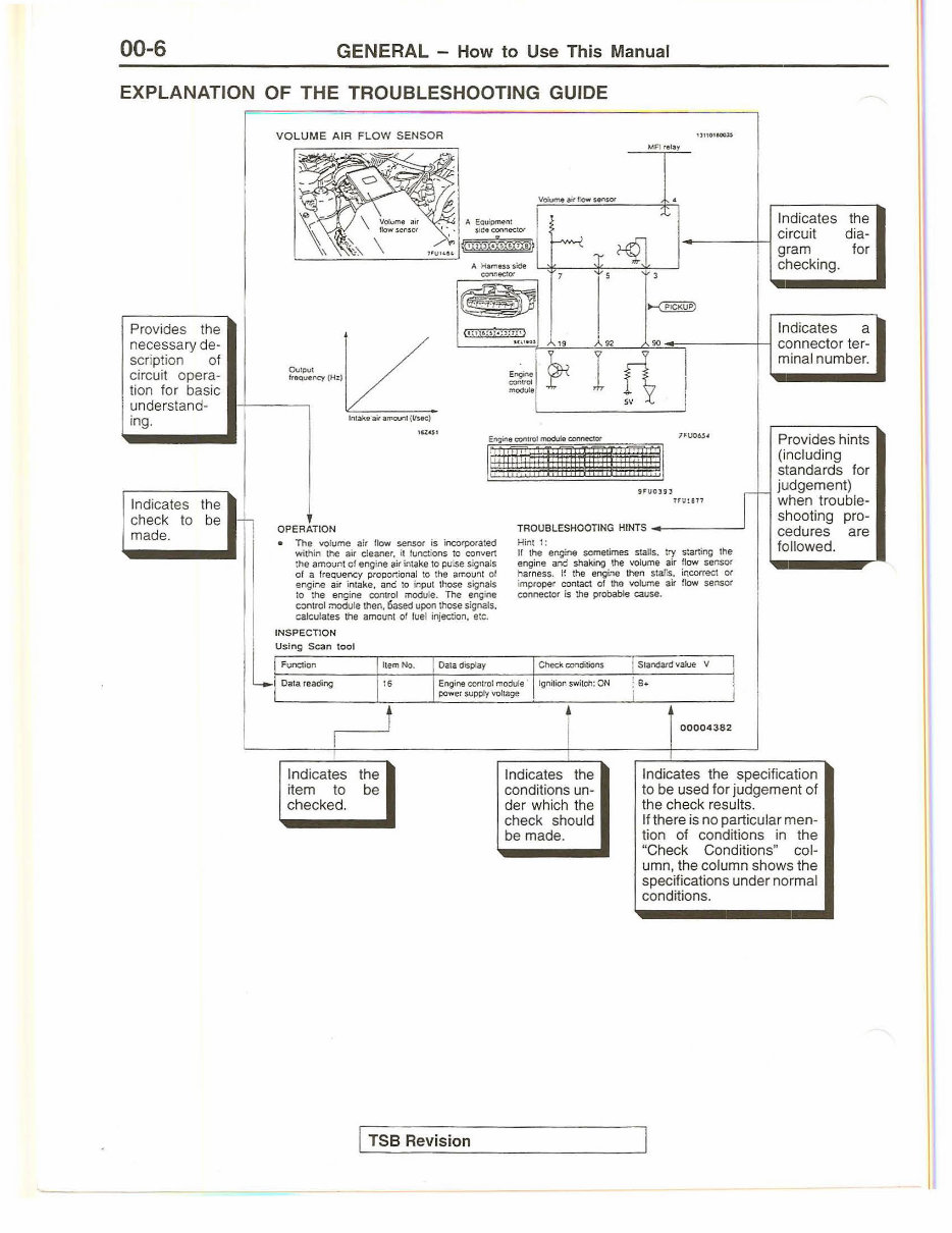
00-6 GENERAL - How to Use This Manual EXPLANATION OF THE TROUBLESHOOTING GUIDE A Hamesss:Ce connector MFirel~y Volume air t:ow senset • 1l110tfOO,J$ Indicates the circuit dia- gram for checking. Provides the necessary de- lL scription of circuit opera- ••+--- ~-.~ -,"u~~cy<HzJ tion for basic understand- 19 '"'1 s 92 90 Indicates a connector ter- minal number. ing. Intake ail amo\rll (Li see) In dicates the check to be made. 1CZ .. S1 ! Hfliit'i iniii !l !TIII! fi !I 7fU06.S4 Provides hints (including standards for judgement) when trouble- shooting pro- cedures are followed. OPERATION • The volume air llow sensor is incorporated within the air cleaner. it functi ons to convert the amount of engine air intake to pulse signals of a frequency proportional to the amount of engine air intake, and to input those signals to the engine control module. The engine control module then, 6ased upon those signals, calculates the amount of fuel injection, etc. INSPECTION llemNo. Data display 91 U0 193 1rr.r:en ~~ TROUBLESHOOTING HINTS ______ __, Hint t: If the engine sometimes stalls. try starting the engine afld shaking the volume ai r flow sensor harness. If the eflgine then stalls, incorrect or improper contact of the volume air flow sensor conflector is the probable cause. Check conditions Stafldard value V IL Using Scan tool Function Oa1a reading 16 Engine control module · power supply voltage I gnition switch: ON ! s .. i I Indicates the item to be checked. TSB Revision i T Indicates the conditions un- der which t he check should be made. 00004382 Indicates the specification to be used for judgement of the check results. If there is no particular men- tion of conditions in the "Check Conditions" col- umn, t he column shows the specifications under normal conditions.
You're Reading a Preview
What's Included?
Lifetime Access
Fast Download Speeds
Online & Offline Access
Access PDF Contents & Bookmarks
Full Search Facility
Print one or all pages of your manual
$33.99$44.99
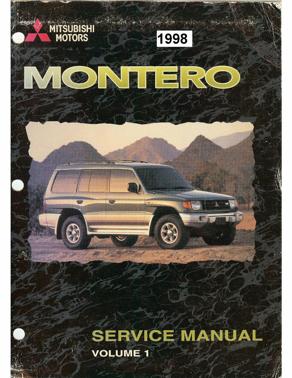
Mitsubishi Montero Pajero Shogun 1998 Service Repair Manual
Whether you're a DIY enthusiast or a professional mechanic, this manual provides access to the same specifications and procedures available to authorized dealer service departments. Even if you don't plan on working on your car yourself, owning and referring to this manual will enhance your understanding and enable you to have more informed discussions with automotive technicians.
These files are in PDF format, allowing you to view them on your PC, Mac, and various devices including many phones and e-readers like the Amazon Kindle. You also have the option to print individual pages as needed, eliminating the risk of the original manual becoming obscured and unreadable due to oil stains.
Upon completion of payment through our secure platform, you can instantly access the product without any shipping costs or waiting for a CD.
Every aspect of the car is covered, including but not limited to general info, engine service and overhauling, transmission, chassis, body, wiring, fuel system, emission control, induction, mechanical, control system, transmission and differentials, troubleshooting and diagnostics, steering and suspension, brakes, ABS, full specifications and torque settings, and service work.
This manual can be beneficial for various purposes, such as diagnosing engine fault symptoms, researching and evaluating the best approach for fixing vehicle problems, testing suspected parts using techniques employed by top mechanics, tracing and verifying wiring diagrams, understanding and analyzing different engine management systems, providing common fixes to communicate with mechanics effectively, checking the quality of mechanic or garage work, testing the vehicle after repair, offering practical quick solutions to problems, and providing common tips about the vehicle before small problems escalate.
If you require a different service manual for another model, make, or year, please visit:
Recently Viewed
5,521,897Happy Clients
2,594,462eManuals
1,120,453Trusted Sellers
15Years in Business
Price:
Actual Price:
Mitsubishi Montero Pajero Shogun 1998 Service Repair Manual




 Lifetime Access




