


31-1
GROUP 31
WHEEL AND TIRE
CONTENTS
GENERAL DESCRIPTION. . . . . . . . . 31-2
TIRE PRESSURE MONITORING SYSTEM
(TPMS) SERVICE PRECAUTIONS . . 31-8
WHEEL AND TIRE DIAGNOSIS . . . . 31-10
WHEEL AND TIRE DIAGNOSIS. . . . . . . . . 31-10
WHEEL BALANCE ACCURACY . . . . . . . . 31-11
TIRE PRESSURE MONITORING
SYSTEM (TPMS) DIAGNOSIS . . . . . 31-14
INTRODUCTION TO DIAGNOSIS . . . . . . . 31-14
TPMS TROUBLESHOOTING STRATEGY. 31-14
TPMS DIAGNOSTIC FUNCTION . . . . . . . . 31-15
TPMS WARNING LIGHT CHECK. . . . . . . . 31-18
DIAGNOSTIC TROUBLE CODE CHART . . 31-19
TPMS DIAGNOSTIC TROUBLE CODE
PROCEDURES . . . . . . . . . . . . . . . . . . . . . . 31-20
TPMS SYMPTOM CHART . . . . . . . . . . . . . 31-48
TPMS SYMPTOM PROCEDURES. . . . . . . 31-49
TPMS SERVICE DATA LIST . . . . . . . . . . . 31-84
TPMS ACTUATOR TEST . . . . . . . . . . . . . . 31-85
TPMS SPECIAL FUNCTION DATA LIST . . 31-85
CHECK AT TPMS RECEIVER . . . . . . . . . . 31-86
SPECIAL TOOLS . . . . . . . . . . . . . . . . 31-87
ON-VEHICLE SERVICE . . . . . . . . . . . 31-88
TIRE INFLATION PRESSURE CHECK . . . 31-88
TIRE WEAR CHECK . . . . . . . . . . . . . . . . . . 31-88
WHEEL RUNOUT CHECK . . . . . . . . . . . . . 31-88
TPMS SPECIAL FUNCTION . . . . . . . . . . . . 31-89
TIRE PRESSURE SENSOR ID
REGISTRATION . . . . . . . . . . . . . . . . . . . . . 31-89
TIRE PRESSURE SENSOR ID CHECK . . . 31-90
TIRE PRESSURE SENSOR CHECK . . . . . 31-91
WHEEL AND TIRE . . . . . . . . . . . . . . . 31-93
INSTALLATION SERVICE POINT . . . . . . . 31-93
WHEEL AND TIRE REPLACEMENT . . . . . 31-93
TIRE PRESSURE MONITORING
SYSTEM (TPMS) . . . . . . . . . . . . . . . . 31-94
TPMS ANTENNA . . . . . . . . . . . . . . . . . . . . 31-94
REMOVAL AND INSTALLATION . . . . . . . . 31-94
TPMS RECEIVER . . . . . . . . . . . . . . . . . . . . 31-96
REMOVAL AND INSTALLATION . . . . . . . . 31-96
TPMS TRANSMITTER . . . . . . . . . . . . . . . . 31-97
REMOVAL AND INSTALLATION . . . . . . . . 31-97
SPECIFICATIONS . . . . . . . . . . . . . . . 31-101
FASTENER TIGHTENING
SPECIFICATION . . . . . . . . . . . . . . . . . . . . . 31-101
GENERAL SPECIFICATIONS . . . . . . . . . . 31-101
SERVICE SPECIFICATIONS . . . . . . . . . . . 31-101
GENERAL DESCRIPTION
TSB Revision
WHEEL AND TIRE
31-2
GENERAL DESCRIPTION
M1311000100093
FEATURE
• Warns driver of low tire pressure by illuminating
the TPMS warning light on the combination meter
• Warns driver of TPMS problems by flashing the
TPMS warning light on the combination meter
TIRE PRESSURE MONITORING SYSTEM
(TPMS)
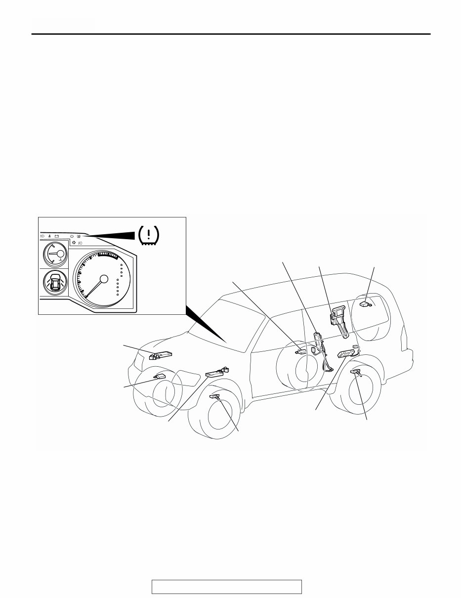
The Tire Pressure Monitoring System (TPMS) con-
sists of five TPMS transmitters (tire pressure sensors
and roll switches) installed in all tires, four TPMS
antennas installed inside the wheel houses, a TPMS
receiver installed inside the lower quarter trim (RH),
and a TPMS warning light on the combination meter.
Each TPMS antenna receives radio frequency signal
output from the TPMS transmitter, the TPMS
receiver interprets the signals and detects abnormal-
ity of tire pressure and/or the system, and the TPMS
warning light illuminates or flashes to alert.
CONSTRUCTION DIAGRAM
AC307575
AC205999
H
C
AT
TEMP
SRS
P
R
N
D
5
4
3
2
1
x1000r/min
2
3
4
5
6 7
8
1
0
AC307585
TPMS ANTENNA
(FRONT: RH)
TPMS RECEIVER
TPMS TRANSMITTER
(FRONT: RH)
TPMS WARNING LIGHT
TPMS ANTENNA
(FRONT: LH)
TPMS ANTENNA
(REAR: RH)
TPMS ANTENNA
(REAR: LH)
TPMS TRANSMITTER
(FRONT: LH)
TPMS TRANSMITTER
(REAR: RH)
TPMS TRANSMITTER
(REAR: LH)
TPMS TRANSMITTER
(SPARE)
AB
NOTE: Each TPMS transmitter has a pressure sensor and roll switch.
GENERAL DESCRIPTION
TSB Revision
WHEEL AND TIRE
31-3
CIRCUIT DIAGRAM
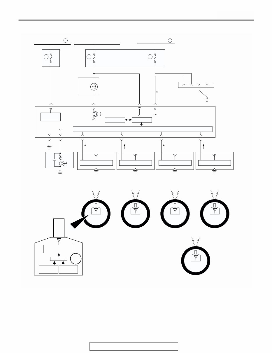
• The TPMS receiver processes input signals from
each TPMS transmitter as well as vehicle speed
signals from the vehicle speed sensor. When the
road tire pressure is low, it sends a warning sig-
nal causing the TPMS warning light to be illumi-
nated. When the TPMS has problems, it sends a
warning signal causing the TPMS warning light to
be flashed.
• The TPMS transmitter includes a roll switch that
senses tire rotation. The TPMS receiver can
determine which tires are rotating (road tire) and
stationary (spare tire).
• For 3 seconds after the ignition switch is turned to
the "ON" position, the TPMS receiver illuminates
the TPMS warning light to check any breaks in
the TPMS warning light circuit.
AC307586
RELAY
BOX
JUNCTION
BLOCK
COMBINATION
METER
TPMS
RECEIVER
DATA LINK
CONNECTOR
FRONT TIRE (LH) FRONT TIRE (RH) REAR TIRE (LH) REAR TIRE (RH)
IGNITION SWITCH (IG1) FUSIBLE LINK
TPMS
POWER
SUPPLY
GND
RECEIVING CIRCUIT
EEPROM
VEHICLE
SPEED
SENSOR
CPU
TPMS TRANSMITTER
TPMS ANTENNA
(FRONT: LH)
CONTROL CIRCUIT
TPMS ANTENNA
(FRONT: RH)
CONTROL CIRCUIT
TPMS ANTENNA
(REAR: LH)
CONTROL CIRCUIT
CPU
TRANSMISSION
CIRCUIT
SPARE TIRE
18
15A
6
10A
10
20A
2 FUSIBLE LINK 1
AB
ANTENNA
TPMS ANTENNA
(REAR: RH)
CONTROL CIRCUIT
PRESSURE
SENSOR
ROLL
SWITCH
BATTERY
GENERAL DESCRIPTION
TSB Revision
WHEEL AND TIRE
31-4
• By connecting the scan tool to the data link con-
nector, data stored in the TPMS receiver (data of
tire pressure and tire pressure sensor ID, the
alarm status and warning history, etc.) can be dis-
played and the tire pressure sensor ID can be
registered.
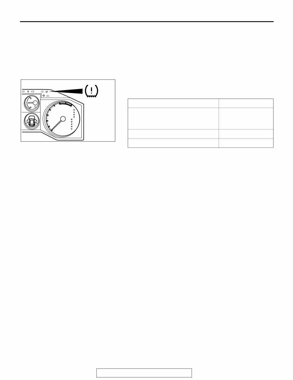
TPMS WARNING LIGHT
The TPMS warning light on the combination meter illuminates
or flashes to alert the driver when signals are entered from the
TPMS receiver.
NOTE: .
• Immediately after the tire pressure sensor ID has been rec-
ognized, the TPMS receiver cannot recognize the road tires
until the vehicle is driven for some time. Therefore, if the
spare tire pressure is low, the TPMS warning light will illumi-
nate.
• The tire pressure monitoring is not applicable for the spare
tire. Therefore, if the low-pressure road tire is used as a
spare tire, the TPMS warning light will go out as soon as the
TPMS receiver recognizes that.
CIRCUMSTANCE WARNING LIGHT
For 3 seconds after the ignition switch
is turned to the "ON" position
(warning light circuit self-check)
Illuminates
TPMS problems Flashes
Low tire pressure of any road tire Illuminates
AC205999
H
C
AT
TEMP
SRS
P
R
N
D
5
4
3
2
1
x1000r/min
2
3
4
5
6 7
8
1
0
AC307585
GENERAL DESCRIPTION
TSB Revision
WHEEL AND TIRE
31-5
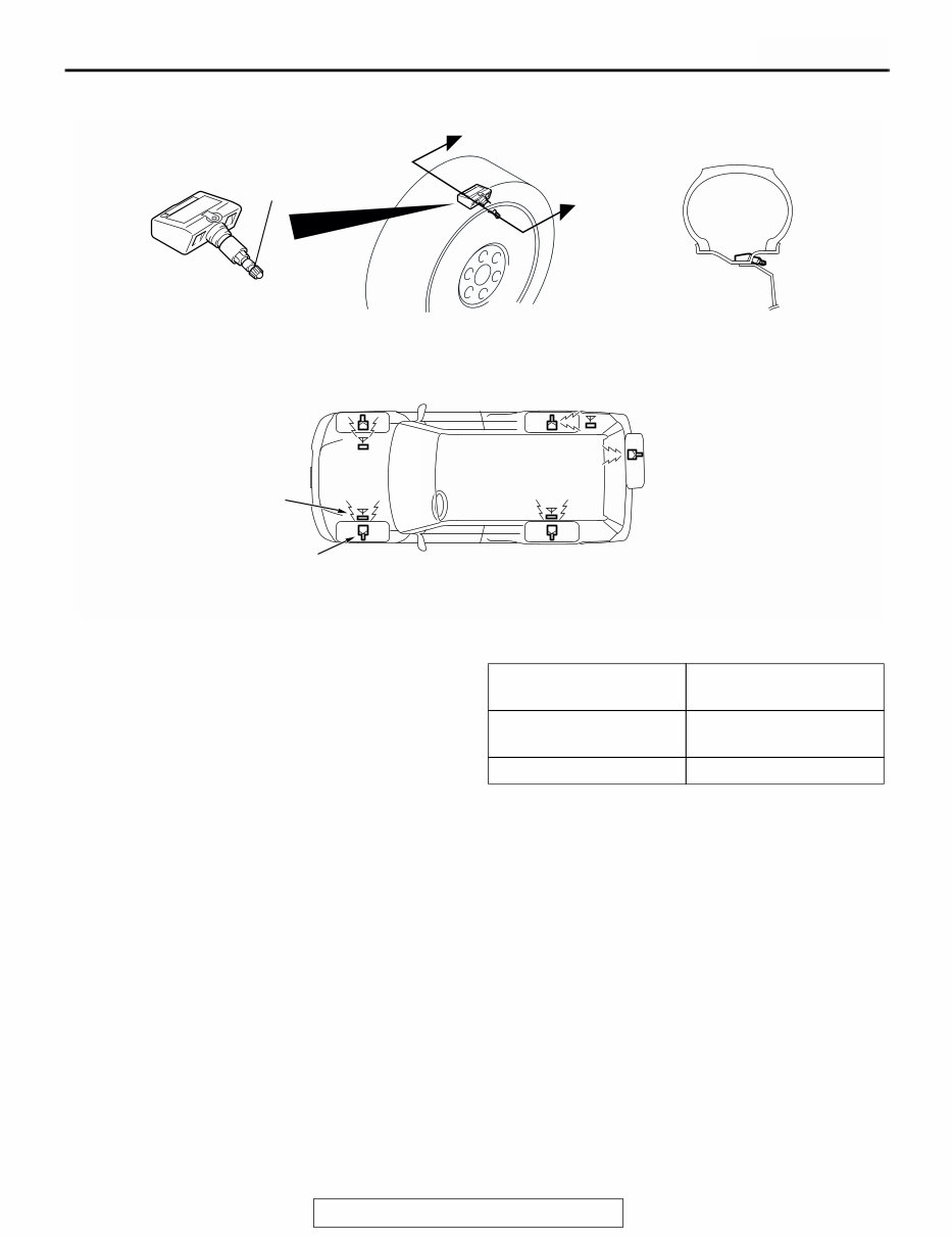
TPMS TRANSMITTER (TIRE PRESSURE SENSOR)
The TPMS transmitter combines the valve and tire
pressure sensor in a single unit. The TPMS transmit-
ters are mounted inside the tires (including the spare
tire). The TPMS transmitter measures tire pressure
directly with its tire pressure sensor and sends radio
frequency signals to the antenna inside the wheel
house. The TPMS transmitter includes a roll switch
that senses tire rotation. The TPMS receiver can
determine which tires are rotating (road tire) and sta-
tionary (spare tire).
NOTE: Use only genuine wheels. The use of
non-genuine wheels may cause the improper instal-
lation of the TPMS transmitters, possibly resulting in
air leakage and damage to the TPMS transmitter.
.
TIRE PRESSURE SAMPLING TIMING
Tire pressure sampling: Once every 30 sec-
onds
.
DATA TRANSMISSION TIMING
If a sampled pressure varies by ±10 kPa
(1.5psi) from the last transmitted pressure
value, an additional transmission will occur.
NOTE: Vehicle moving = vehicle speed: approxi-
mately 30 km/h (19 mph) or more <roll switch: ON>
NOTE: Service period = First 15 minutes after vehi-
cle stops <roll switch: OFF>
NOTE: Vehicle stationary = Situations except vehicle
moving and service period <roll switch: OFF>
AC307594
AC307583
AC307584
AB
VALVE
TPMS TRANSMITTER
(TIRE PRESSURE SENSOR)
A
SECTION A - A
A
TPMS
ANTENNA
TPMS
TRANSMITTER
VEHICLE STATUS TRANSMISSION
TIMING
At vehicle moving and
service period
once every 1 minute
At vehicle stationary once every 1 hour
You're Reading a Preview
What's Included?
 Lifetime Access
Fast Download Speeds
Offline Viewing
Access Contents & Bookmarks
Full Search Facility
Print one or all pages of your manual
$32.99
2004 Mitsubishi MonteroSport Service Repair Manual
Viewed 68 Times Today

What's Included?
Lifetime Access
Fast Download Speeds
Offline Viewing
Access Contents & Bookmarks
Full Search Facility
Print one or all pages of your manual
$32.99

Secure transaction
What's Included?
Lifetime Access
Fast Download Speeds
Offline Viewing
Access Contents & Bookmarks
Full Search Facility
Print one or all pages of your manual
Description
The 2004 Mitsubishi MonteroSport Service Repair Manual is a comprehensive resource for professional mechanics and DIY enthusiasts. It includes service and repair procedures, assembly and disassembly instructions, as well as wiring diagrams for the following VINs (except sequence number):
- JA4LS21R_4J
- JA4LS31R_4J
- JA4MT21R_4J
- JA4MT31R_4J
The manual covers the 6G74 3.5L engine model and includes the following volumes:
- Volume 1: General, Engine, Engine Lubrication, Fuel
- Volume 2: Fuel, Engine Cooling, Intake and Exhaust, Engine Electrical, Engine and Emission Control, Automatic Transmission
- Volume 3: Propeller Shaft, Rear Axle, Wheel and Tire, Power Plant Mount, Front Suspension, Rear Suspension, Service Brakes, Parking Brakes, Steering, Body, Exterior, Interior and Supplemental Restraint System (SRS)
- Volume 4: Chassis Electrical, Heater, Air Conditioning and Ventilation, Component Locations, Configuration Diagrams and Splice Locations, Circuit Diagrams
This high-quality manual is available in PDF format, making all pages printable for instant access without any shipping costs or the need to wait for a CD-ROM. It is compatible with all versions of Windows, Mac, and Linux and requires Adobe Reader or similar software. The language of the manual is English.
Thank you for visiting!


