

2001 Mitsubishi Pajero (NM) Service & Repair Manual
What's Included?
Fast Download Speeds
Offline Viewing
Access Contents & Bookmarks
Full Search Facility
Print one or all pages of your manual

DIESEL FUEL
<4D5-STEP III>
Click on the applicable bookmark to selected the required model year.

13E-1
DIESEL FUEL
<4D5-STEP III>
CONTENTS
GENERAL 2 .................................
Outline of Change 2 ............................
GENERAL INFORMATION 2 ...................
SERVICE SPECIFICATIONS 4 .................
SEALANT 4 ..................................
SPECIAL TOOLS 5 ...........................
TROUBLESHOOTING 6 .......................
ON-VEHICLE SERVICE 55 ....................
Injection Nozzle Check and Adjustment 55 .........
Injection Timing Check and Adjustment 55 .........
Idle Speed Check and Adjustment 55 .............
Accelerator Pedal Position Sensor (APS)
Adjustment 56 .................................
Control Relay Continuity Check 57 ................
Accelerator Pedal Position Sensor (APS)
Check 57 ......................................
Idle Switch Check 58 ............................
Boost Air Temperature Sensor (Intake Air
Temperature Sensor) Check 58 ..................
Engine Coolant Temperature Sensor Check 59 .....
Evacuation of Water from Fuel Filter 59 ............
Fuel Filter Cartridge Replacement 60 ..............
Evacuation of Air from Fuel Line 60 ...............
EGR Valve Position Sensor Check 60 .............
Fuel Injection Pump Check 61 ....................
Throttle Solenoid Valve Check 62 .................
Throttle Actuator Check 63 ......................
Variable Geometry Solenoid Valve Check 63 .......
EGR Control Solenoid Valve Check 63 ............
FUEL INJECTION NOZZLE 64 .................
FUEL INJECTION PUMP 64 ...................
CRANKSHAFT POSITION SENSOR 66 .........
ENGINE-ECU 66 .............................

DIESEL FUEL <4D5-step III>- General/General Information 13E-2
GENERAL
OUTLINE OF CHANGE
An electronically-controlled injection pump has been added in order to comply with Regulation STEP
III. Due to this, the following service procedures have been added.
GENERAL INFORMATION
The electronically-controlled fuel injection system consists of sensors which detect the condition of the
diesel engine, an engine-ECU which controls the system based on signals from these sensors, and actuators
which operate according to control commands from the engine-ECU.
The engine-ECU carries out operations such as fuel injection rate control, fuel injection timing control
and idle up control. In addition, the engine-ECU is equipped with several self-diagnosis functions which
make troubleshooting easier in the event that a problem develops.
FUEL INJECTION RATE CONTROL
The fuel injection completion timing is controlled by means of a solenoid-type spill valve to ensure that
the optimum amount of fuel is supplied to the engine in accordance with gradual changes in the engine
running condition.
Before fuel injection starts, the solenoid-type spill valve is on (energized), so that the valve is closed.
As the plunger turns and rises, fuel is sent out under pressure, and when the fuel flow rate reaches
the target value for fuel injection, the solenoid-type spill valve turns off. When the solenoid-type spill
valve turns off, the fuel under high pressure inside the plunger is leaked out into the pump chamber
and fuel injection is completed.
FUEL INJECTION TIMING CONTROL
The position of the injection pump timer piston is controlled so that fuel injection is carried out at the
optimum timing in accordance with the engine running condition.
The timer piston position is determined by duty control of the timing control solenoid valve which is located
in the line between the high-pressure chamber and the low-pressure chamber of the timer piston.
The fuel injection timing is advanced by increasing the control duty of the timing control solenoid valve.
IDLE SPEED CONTROL
Controlling the fuel injection rate in accordance with the engine running condition maintains the idle speed
at the optimum condition.
SELF-DIAGNOSIS FUNCTION
D When an abnormality is detected in any of the sensors or actuators, the engine warning lamp illuminates
to warn the driver.
D When an abnormality is detected in any of the sensors or actuators, a diagnosis code number
corresponding to the problem which occurred is output.
D The RAM data relating to the sensors and actuators which is stored in the engine-ECU can be read
using the MUT-II. In addition, the actuators can be force-driven under certain conditions.
OTHER CONTROL FUNCTIONS
1. Power Supply Control
When the ignition switch is turned to ON, the relay turns on and power is supplied to components
such as the timing control solenoid valve.
2. Intake Air Throttle Control
When the engine-ECU detects an abnormality in any of the sensors or actuators, the throttle valve
is half opened to restrict the amount of intake air in order to prevent the vehicle from running away.
3. A/C Relay Control
Turns the compressor clutch of the A/C ON and OFF
4. Condenser Fan Motor Relay Control
Controls the condenser fan motor relay based on the A/C switch, engine coolant temperature and
vehicle speed input signals.
5. Glow Control
Refer to GROUP 16.
6. EGR Control
Refer to GROUP 17.
DIESEL FUEL <4D5-step III>- General Information 13E-3
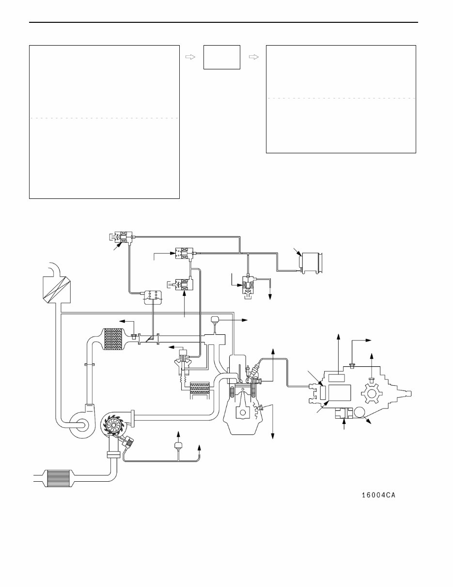
CONTROL SYSTEM DIAGRAM
L1. Pump speed sensor
L2. Crank angle sensor
L3. Engine coolant temperature sensor
L4. Boost pressure sensor
L5. Fuel temperature sensor
L6. Boost air temperature sensor
L7. Control sleeve position sensor
L8. Timer piston position sensor
L9. EGR valve position sensor
L10. Variable geometry control pressure sensor
D Accelerator pedal position sensor (main)
D Accelerator pedal position sensor (sub)
D Idle switch
D Power supply
D Ignition switch-IG
D Ignition switch-ST
D Vehicle speed sensor
D A/C switch
D A/C relay switch
D Injection volume adjusting ROM
D Barometric pressure sensor (ECU built-in)
l1. GE actuator (electronic governor)
l2. Timing control valve
l3. EGR control solenoid valve No. 1
l4. EGR control solenoid valve No. 2
l5. Throttle solenoid valve
l6. Fuel cut solenoid valve
l7. Variable geometry solenoid valve
D Control relay
D A/C relay
D Condenser fan relay
D Glow indicator lamp
D Glow plug relay
D Engine warning lamp
D Diagnosis output
Engine-
ECU
L8 Timer piston
position
sensor
L2 Crank angle
sensor
L9 EGR
valve position
sensor
L10 Variable geometry control
pressure sensor
L6 Boost air
temperature sensor
L4 Boost pressure
sensor
L3 Engine coolant
temperature sensor
L7 Control
sleeve
position
sensor
l7
Variable geometry
solenoid valve
l3
EGR control
solenoid valve No. 1
l1 GE actuator
l5 Throttle solenoid valve
l6 Fuel cut
solenoid
valve
Vacuum pump
Alternator
To variable
geometry actuator
l2 Timing control
valve
Catalytic converter
Variable
geometry
actuator
Variable geometry
turbocharger
Throttle
actuator
EGR valve
To variable geome-
try solenoid valve
L1 Pump speed
sensor
L5 Fuel
temperature
sensor
l4 EGR control
solenoid
valve No. 2
DIESEL FUEL <4D5-step III>- Service Specifications/Sealant 13E-4
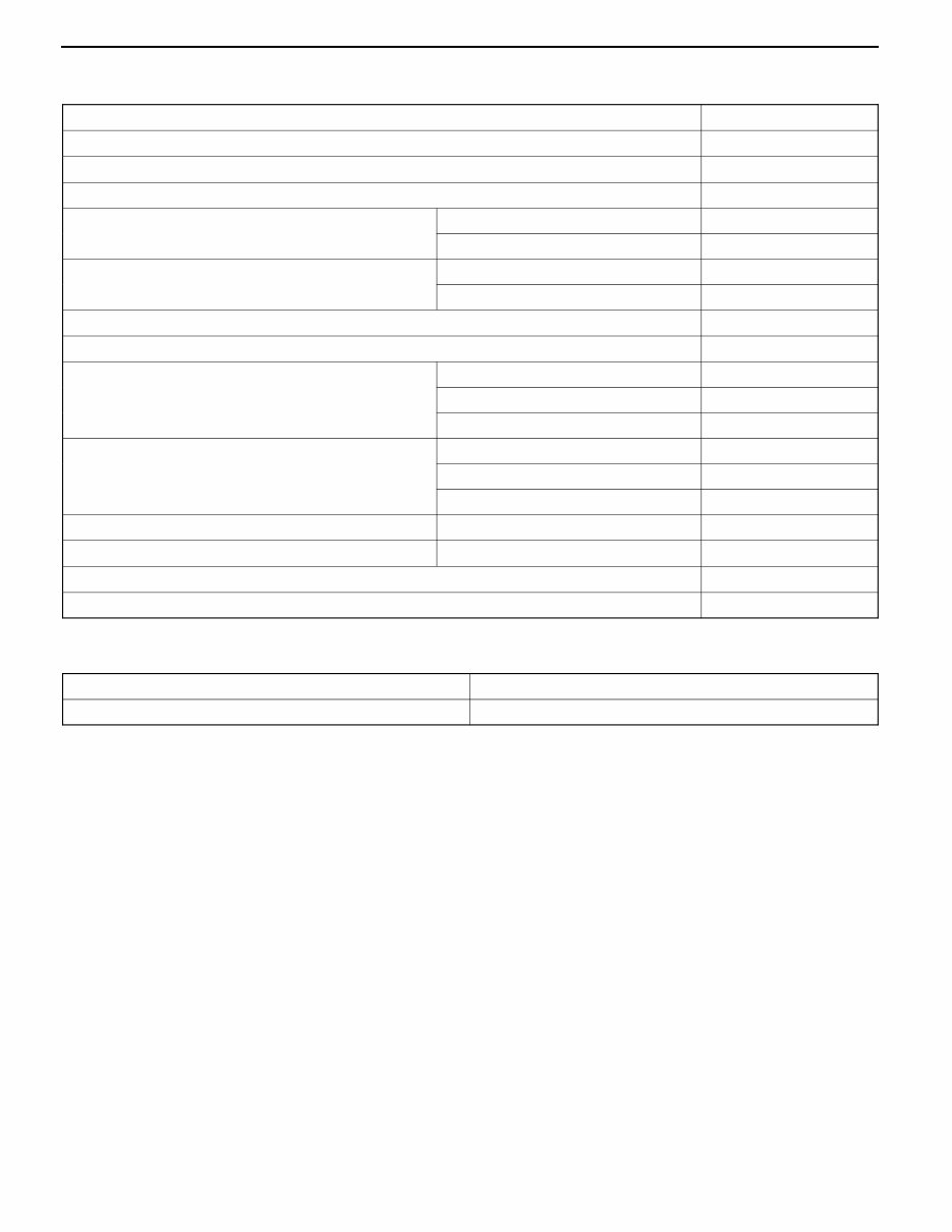
SERVICE SPECIFICATIONS
Item Standard value
Fuel injection initial pressure kPa 14,710 - 15,490
Accelerator pedal position sensor reference voltage V 0.985 - 1.085
Accelerator pedal position sensor resistance kΩ 3.5 - 6.5
Boost air temperature sensor (Intake air temperature
) it kΩ
When the temperature is 20_C 2.3 - 3.0
sensor) resistance kΩ
When the temperature is 80_C 0.30 - 0.42
Engine coolant temperature sensor resistance kΩ When the temperature is 20_C 2.1 - 2.7
When the temperature is 80_C 0.26 - 0.36
Fuel cut solenoid valve resistance Ω 6.8 - 9.2
Timing control valve resistance Ω 10.8 - 11.2
Timer piston position sensor resistance Ω Connector terminals No. 1 - No. 2 160 - 168
Connector terminals No. 1 - No. 3 80 - 84
Connector terminals No. 2 - No. 3 80 - 84
Control sleeve position sensor resistance Ω Connector terminals No. 4 - No. 12 11.2 - 12.4
Connector terminals No. 4 - No. 8 5.6 - 6.2
Connector terminals No. 8 - No. 12 5.6 - 6.2
GE actuator (electronic governor) resistance Ω Connector terminals No. 6 - No. 10 0.64 - 0.72
Fuel temperature sensor resistance kΩ Connector terminals No. 7 - No. 11 1.4 - 2.6
Pump speed sensor resistance kΩ 1.36 - 1.84
Throttle solenoid valve resistance Ω 36 - 44
SEALANT
Item Specified sealant
Engine coolant temperature sensor 3M Nut Locking Part No. 4171 or equivalent
You're Reading a Preview
What's Included?
Fast Download Speeds
Offline Viewing
Access Contents & Bookmarks
Full Search Facility
Print one or all pages of your manual
$31.99
Viewed 31 Times Today


Secure transaction
What's Included?
Fast Download Speeds
Offline Viewing
Access Contents & Bookmarks
Full Search Facility
Print one or all pages of your manual
$31.99
- This is a comprehensive service and repair manual for the MITSUBISHI PAJERO NM 2001, containing essential technical information for maintenance and troubleshooting.
- It is designed for both professional mechanics and DIY enthusiasts, providing easy-to-read text sections with high-quality diagrams and instructions.
- The manual covers every single detail of the MITSUBISHI PAJERO NM 2001, offering step-by-step instructions based on complete machine disassembly.
- It includes accurate, clear, and concise text, combined with illustrations, making it suitable for individuals with basic mechanical knowledge to safely and easily service and repair their vehicle.
- Comprehensive diagrams, in-depth illustrations, and all the manufacturer's specifications and technical information are included.
- It is available in a printable file format, with zoom in/out capability, and is compatible with all versions of Windows and Mac.
- The manual is suitable for immediate access without any waiting or shipping fees, allowing users to start repairs right away.
- It covers a wide range of topics including MOT test checks, roadside repairs, routine maintenance, engine and associated systems, cooling, heating and air conditioning systems, fuel and exhaust systems, electrical systems, transmission, braking system, suspension and steering systems, body equipment, electrical systems, wiring diagrams, tools and working facilities, general repair procedures, fault finding, and a glossary of technical terms.
Get your MITSUBISHI PAJERO NM 2001 fully serviced and repaired with this comprehensive manual.


