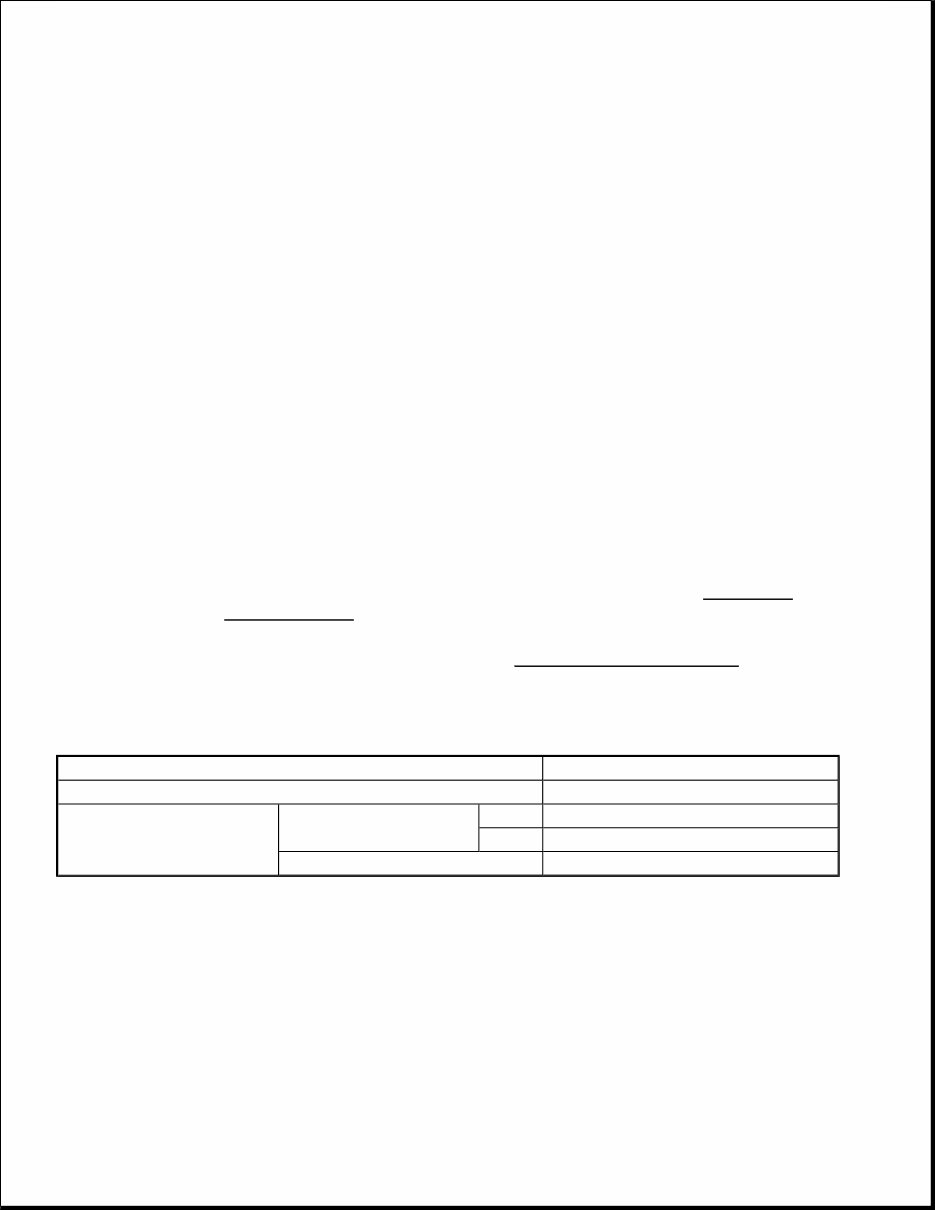
BRAKES Anti-Lock Braking System (ABS) - Outlander GENERAL INFORMATION The 4 ABS ensures directional stability and control during hard braking. This ABS uses a 4-sensor system that controls all four wheels independently of each other. EBD *1 (Electronic Brake-force Distribution system) control can obtain ideal rear wheel brake force. The magnetic encoder for wheel speed detection has been installed instead of the rotor as the wheel speed sensor. For wiring harness saving and secure data communication, CAN *2 bus has been adopted as a tool of communication with another ECU. Fail-safe function which ensures that safety is maintained. Diagnostic function which provides improved serviceability. Specifications ITEM SPECIFICATIONS CHART CONSTRUCTION DIAGRAM NOTE: *1 : EBD (Electronic Brake-force Distribution) *2 : For further details on CAN communication, refer to GENERAL INFORMATION . On vehicles with ASC, the ABS system is controlled by the ASC-ECU. For the system construction, refer to GENERAL INFORMATION . Item Specifications ABS control type 4 sensors Wheel speed sensor Magnetic encoder Front 86 (N pole: 43, S pole: 43) Rear 86 (N pole: 43, S pole: 43) Type Semiconductor
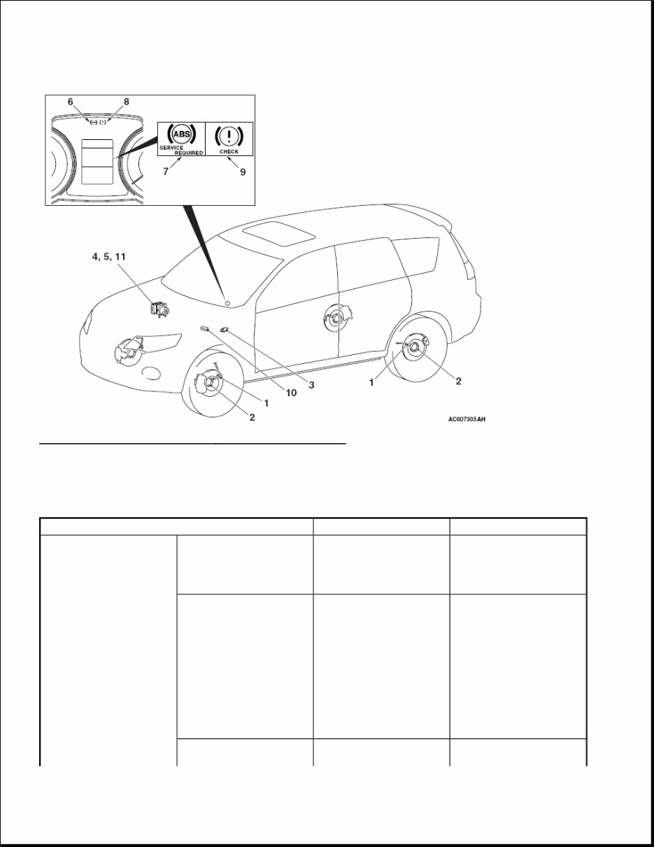
Fig. 1: Anti Lock Brake System - Construction Diagram Courtesy of MITSUBISHI MOTOR SALES OF AMERICA. MAIN COMPONENTS AND FUNCTIONS MAIN COMPONENTS AND FUNCTIONS CHART Name of part Number Outline of function Sensor Wheel speed sensor 1 Outputs the frequency signal in proportion to the rotation speed of each wheel to ABS-ECU. Magnetic encoder for wheel speed detection 2 When the magnetic encoder for wheel speed detection (a plate on which north and south pole sides of the magnets are arranged alternately) rotates, the wheel speed sensor outputs frequency pulse signal in proportion to each wheel speed. Stoplight switch 3 Outputs the signal indicating whether the
brake pedal is depressed or not to ABS-ECU. G sensor <4WD> 4 Incorporated in ABS- ECU, and detects the longitudinal acceleration of the vehicle. Actuator Hydraulic unit 5 Drives the solenoid valve using the signal from ABS-ECU, and controls the brake fluid pressure for each wheel. ABS warning light 6 Informs the driver of the system status by illuminating, flashing, or turning off the warning light according to the signal from ABS-ECU. ABS warning display 7 Informs the driver of the system status by illuminating or turning off the warning light according to the signal from ABS-ECU. Brake warning light 8 Used as the warning light for the parking brake, brake fluid level, and EBD control. Informs the driver of the system status by illuminating or turning off the warning light according to the signal from ABS-ECU. Brake warning display 9 Used as the warning light for the parking brake, brake fluid level, and EBD control. Informs the driver of the system status by illuminating or turning off the warning light according to the signal from ABS-ECU. Diagnosis connector 10 Outputs the diagnosis code and establishes the communication with scan tool. ABS-ECU 11 Controls actuators
SPECIFICATIONS SERVICE SPECIFICATIONS SERVICE SPECIFICATIONS CHART ABS DIAGNOSIS INTRODUCTION The anti-lock brake system (ABS) operates differently from conventional brake systems. These differences include sounds, sensations, and vehicle performance that owners and service technicians who are not familiar with ABS may not be used to. Some operational characteristics may seem to be malfunctions, but they are simply signs of normal ABS operation. When diagnosing the ABS system, keep these operational characteristics in mind. Inform the owner of the kind of performance characteristics to expect from an ABS-equipped vehicle. ABS DIAGNOSTIC TROUBLE CODE DETECTION CONDITIONS ABS diagnostic trouble codes (ABS DTCs) are set under different conditions, depending on the malfunction detected. Most ABS DTCs will only be set during vehicle operation. Some ABS DTCs will also be set during the ABS self-check immediately after the engine is started. When you check if an ABS DTC will be displayed again after the DTC has been erased, you should duplicate the ABS DTC set conditions. Depending on the detection timing and set conditions for the specific ABS DTC, you must either drive the vehicle or turn the engine off and restart it. To set the proper conditions for that DTC again, refer to "ABS DTC SET CONDITIONS" for each ABS DTC that you are trying to reset. ABS DIAGNOSTIC TROUBLESHOOTING STRATEGY Use these steps to plan your diagnostic strategy. If you follow them carefully, you will be sure that you have (described above) based on the signals coming from each sensor. Controls the self- diagnosis and fail-safe functions. Controls the diagnosis function (scan tool compatible). Item Standard value Wheel speed sensor current mA 5.9 - 8.4 or 11.8 - 16.8 Wheel speed sensor insulation resistance Mohms 5 or more
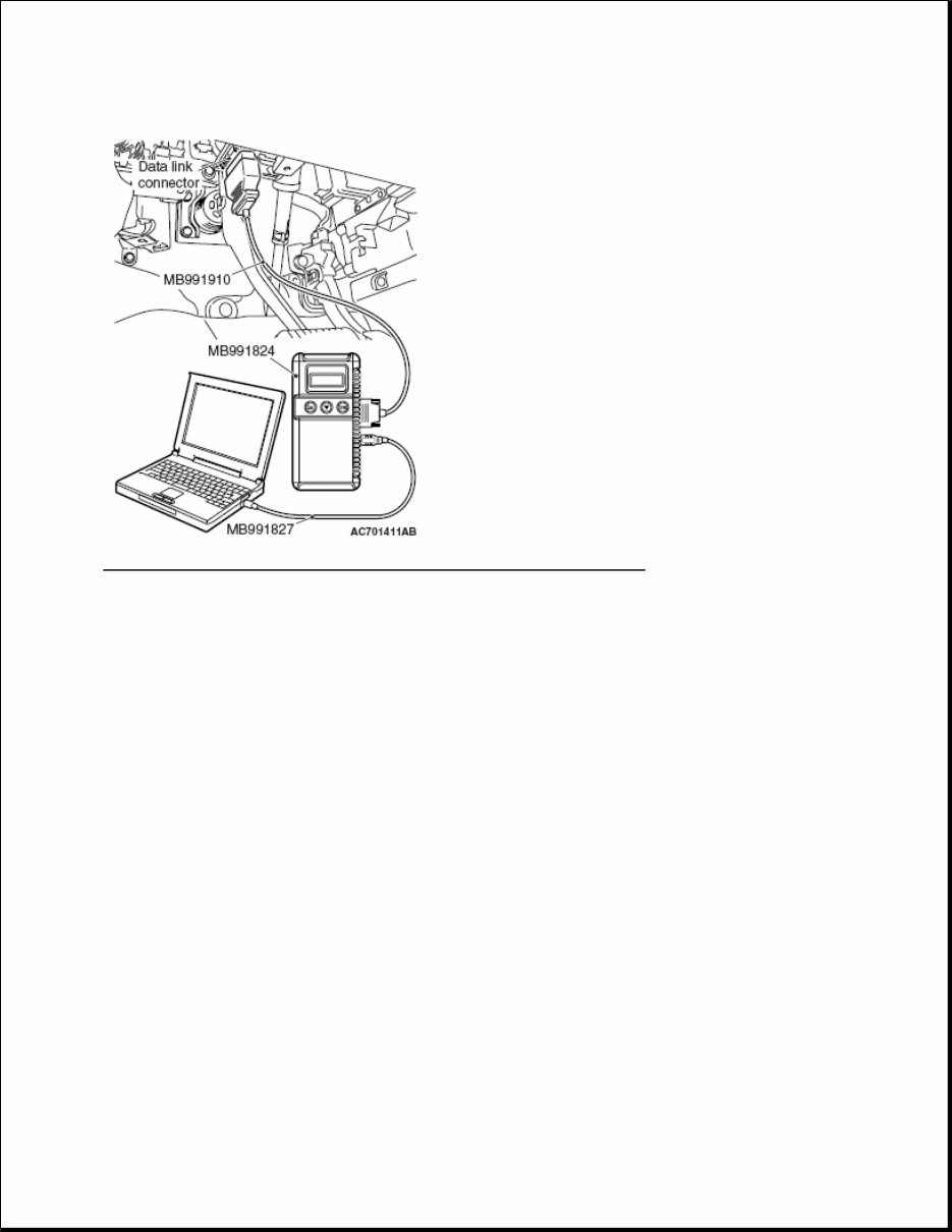
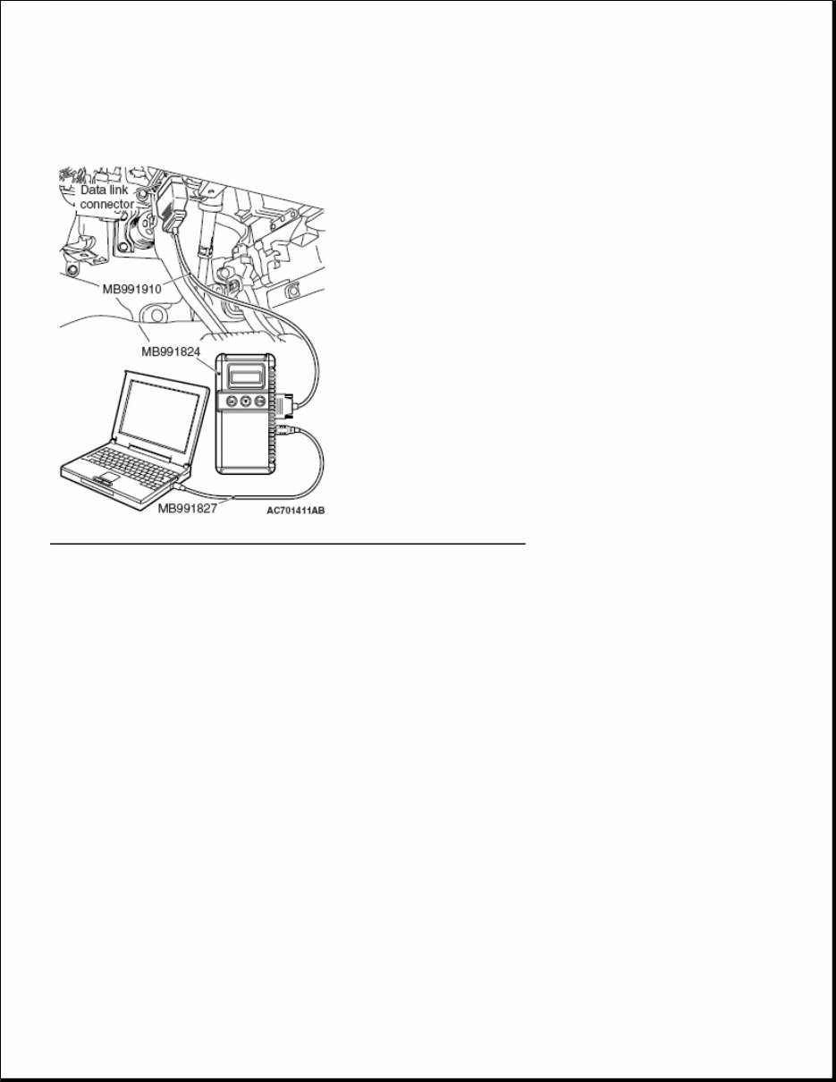
exhausted most of the possible ways to find an ABS fault. 1. Gather information about the problem from the customer. 2. Verify that the condition described by the customer exists. 3. Check the vehicle for any ABS DTC. 4. If you cannot verify the condition and there are no ABS DTCs, the malfunction is intermittent. Refer to HOW TO COPE WITH INTERMITTENT MALFUNCTIONS . 5. If you can verify the condition but there are no ABS DTCs, or the system cannot communicate with the scan tool, check that the basic brake system is operating properly. If the basic brake system is not operating properly, refer to the BASIC BRAKE SYSTEM DIAGNOSIS . If the basic brake system is operating properly, refer to BRAKE BOOSTER OPERATION CHECK . 6. If there is an ABS DTC, record the number of the DTC, then erase the DTC from the memory using the scan tool. 7. Recreate the ABS DTC set conditions to see if the same ABS DTC will set again. If the same ABS DTC sets again, perform the diagnostic procedures for the DTC. Refer to DIAGNOSTIC TROUBLE CODE CHART . If you cannot get the same ABS DTC to set again, the malfunction is intermittent. Refer to HOW TO COPE WITH INTERMITTENT MALFUNCTIONS . DIAGNOSIS FUNCTION HOW TO CONNECT THE SCAN TOOL (M.U.T.-III) Required Special Tools: MB991958: Scan Tool (M.U.T.-III Sub Assembly) MB991824: Vehicle Communication Interface (V.C.I.) MB991827: M.U.T.-III USB Cable MB991910: M.U.T.-III Main Harness A 1. Ensure that the ignition switch is at the "LOCK" (OFF) position. 2. Start up the personal computer. 3. Connect special tool MB991827 to special tool MB991824 and the personal computer. 4. Connect special tool MB991910 to the special tool MB991824. 5. Connect special tool MB991910 to the data link connector. 6. Turn the power switch special tool MB991824 to the "ON" position. CAUTION: To prevent damage to scan tool MB991958, always turn the ignition switch to the "LOCK" (OFF) position before connecting or disconnecting scan tool MB991958.
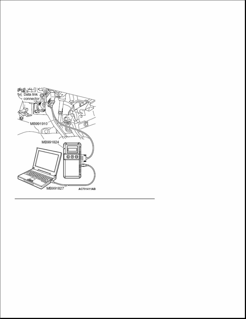
Fig. 2: Connecting Special Tool MB991910 To Data Link Connector Courtesy of MITSUBISHI MOTOR SALES OF AMERICA. 7. Start the M.U.T.-III system on the personal computer. HOW TO READ AND ERASE DIAGNOSTIC TROUBLE CODES Required Special Tools: MB991958: Scan Tool (M.U.T.-III Sub Assembly) MB991824: Vehicle Communication Interface (V.C.I.) MB991827: M.U.T.-III USB Cable MB991910: M.U.T.-III Main Harness A NOTE: When the special tool MB991824 is energized, the special tool MB991824 indicator light will be illuminated in a green color. NOTE: Disconnect the scan tool MB991958 in the reverse order of the connecting sequence, making sure that the ignition switch is at the "LOCK" (OFF) position. CAUTION: To prevent damage to scan tool MB991958, always turn the ignition switch to the "LOCK" (OFF) position before connecting or disconnecting scan tool MB991958. NOTE: If the battery voltage is low, diagnostic trouble codes will not be set. Check the
Fig. 3: Connecting Special Tool MB991910 To Data Link Connector Courtesy of MITSUBISHI MOTOR SALES OF AMERICA. 1. Connect scan tool MB991958 to the data link connector. 2. Turn the ignition switch to the "ON" position. 3. Select "System Select." 4. Select "ABS/ASC/ASTC" from the system list, and select the "OK" button. 5. Select "Diagnostic Trouble Code." 6. If a DTC is set, it is shown. 7. Choose "DTC erase" to erase the DTC. HOW TO READ DATA LIST Required Special Tools: MB991958: Scan Tool (M.U.T.-III Sub Assembly) MB991824: Vehicle Communication Interface (V.C.I.) MB991827: M.U.T.-III USB Cable MB991910: M.U.T.-III Main Harness A battery if scan tool MB991958 does not display. CAUTION: To prevent damage to scan tool MB991958, always turn the ignition switch to the "LOCK" (OFF) position before connecting or disconnecting scan
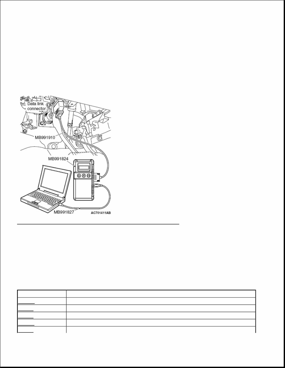
1. Connect scan tool MB991958 to the data link connector. 2. Turn the ignition switch to the "ON" position. 3. Select "System Select." 4. Select "ABS/ASC/ASTC" from the system list, and select the "OK" button. 5. Select "Data List." Fig. 4: Connecting Special Tool MB991910 To Data Link Connector Courtesy of MITSUBISHI MOTOR SALES OF AMERICA. HOW TO PERFORM ACTUATOR TEST Required Special Tools: MB991958: Scan Tool (M.U.T.-III Sub Assembly) MB991824: Vehicle Communication Interface (V.C.I.) MB991827: M.U.T.-III USB Cable MB991910: M.U.T.-III Main Harness A tool MB991958. CAUTION: To prevent damage to scan tool MB991958, always turn the ignition switch to the "LOCK" (OFF) position before connecting or disconnecting scan tool MB991958.
1. Connect scan tool MB991958 to the data link connector. 2. Turn the ignition switch to the "ON" position. 3. Select "System Select." 4. Select "ABS/ASC/ASTC" from the system list, and select the "OK" button. 5. Choose "Actuator Test" from "ABS" screen. 6. Choose an appropriate item and select the "OK" button. Fig. 5: Connecting Special Tool MB991910 To Data Link Connector Courtesy of MITSUBISHI MOTOR SALES OF AMERICA. DIAGNOSTIC TROUBLE CODE CHART DIAGNOSTIC TROUBLE CODE CHART CAUTION: During diagnosis, a DTC code associated with other systems may be set when the ignition switch is turned on with connector(s) disconnected. On completion, check all systems for DTCs. If DTC code(s) are set, erase them all. DTC Inspection item C100A Abnormality in FL wheel speed sensor circuit C1015 Abnormality in FR wheel speed sensor circuit C1020 Abnormality in RL wheel speed sensor circuit C102B Abnormality in RR wheel speed sensor circuit C1011 Abnormality in FL wheel speed sensor signal
This is the complete official full factory service repair manual for the Mitsubishi Outlander 2011. It is your number one source for repair and service information, providing step-by-step instructions based on the complete disassembly of the machine. This manual is useful for both professional mechanics and DIY enthusiasts.
The manual covers general maintenance, troubleshooting, engine service/repair, transmission service/repair, brake system, wiring diagram, electrical system, suspension, periodic lubrication, steering, cooling system, fuel injection, fuel system, emission system, heater/air conditioning, engine control system, chassis/body, restraint system, interior, differential/drive, and axle, among much more.
It comes in .PDF format and can work under all PC-based Windows operating systems and Mac as well. It saves to your hard drive and can be burned to CD-ROM. All pages are printable. No need to pay for shipping and wait for the overpriced paper textbook or CD-ROM to arrive via snail mail.
Product Details:
File Format: .PDF
Language: English
Printable: without any restriction
Delivery: link will appear on the checkout page after payment is complete
Requirements: Adobe Reader
This is a full professional quality in-depth service & repair manual for Mitsubishi Outlander 2011. It covers general information, specifications, engine removal, wiring diagrams, oil types, periodic maintenance and tune-up procedures, engine servicing, disassembly, reassembly, electrical system, brakes, steering, suspension, servicing information, service data, complete engine service, fuel system service, all factory repair procedures, and much more.
Mitsubishi Outlander 2011 Workshop Manual, Mitsubishi Outlander 2011 Service Manual, Mitsubishi Outlander 2011 Repair Manual, Mitsubishi Outlander 2011 Full Manual