


GROUP 00
GENERAL <BODY AND CHASSIS>
CONTENTS
HOW TO USE THIS MANUAL..........00-3
TROUBLESHOOTING GUIDELINES......00-6
HOW TO USE TROUBLESHOOTING/
INSPECTION SERVICE POINTS.......00-6
TROUBLESHOOTING CONTENTS........00-6
HOW TO USE THE INSPECTION PROCEDURES
................................00-9
CONNECTOR MEASUREMENT SERVICE POINTS
...............................00-12
CONNECTOR INSPECTION SERVICE POINTS
...............................00-14
HOW TO COPE WITH INTERMITTENT
MALFUNCTIONS...................00-15
HOW TO TREAT PAST TROUBLE......00-17
INSPECTION SERVICE POINTS FOR A BLOWN
FUSE...........................00-18
VEHICLE IDENTIFICATION.........00-18
VEHICLE IDENTIFICATION CODE PLATE
...............................00-20
PRECAUTIONS BEFORE SERVICE.....00-26
SUPPLEMENTAL RESTRAINT SYSTEM (SRS)
...............................00-26
HOW TO PERFORM VEHICLE IDENTIFICATION
NUMBER (VIN) WRITING...........00-26
INITIALIZATION PROCEDURE FOR LEARNING
VALUE IN MFI ENGINE............00-30
ENGINE IDLING LEARNING PROCEDURE
...............................00-31
SERVICING ELECTRICAL SYSTEM....00-32
VEHICLE WASHING................00-33
APPLICATION OF ANTI-CORROSION AGENTS
AND UNDERCOATS.................00-33
SCAN TOOL (MULTI USE TESTER { M.U.T.-
III } SUB ASSEMBLY)............00-33
CODING LIST....................00-34
TOWING AND HOISTING............00-42
GENERAL DATA AND SPECIFICATIONS
...............................00-46
TIGHTENING TORQUE..............00-48
LUBRICATION AND MAINTENANCE....00-49
RECOMMENDED LUBRICANTS AND LUBRICANT
CAPACITIES TABLE...............00-51
SCHEDULED MAINTENANCE TABLE....00-53
MAINTENANCE SERVICE............00-56
1. FUEL SYSTEM (TANK, PIPE LINE AND
CONNECTION, AND FUEL TANK FILLER TUBE
CAP) (CHECK FOR LEAKS).........00-56
00-1
Continued on next page

2. FUEL HOSES (CHECK CONDITION)
...............................00-56
3. AIR CLEANER ELEMENT (REPLACE)
...............................00-56
4. EVAPORATIVE EMISSION SYSTEM
(EXCEPT EVAPORATIVE EMISSION
CANISTER) (CHECK FOR CLOGGING)
...............................00-57
5. SPARK PLUGS (REPLACE).......00-57
6. INTAKE AND EXHAUST VALVE CLEARANCE
<INTAKE SIDE ONLY> (INSPECT AND
ADJUST)........................00-57
7. TIMING BELT (REPLACE).......00-58
8. DRIVE BELT (FOR GENERATOR, WATER
PUMP, POWER STEERING OIL PUMP) (CHECK
CONDITION).....................00-58
9. EXHAUST SYSTEM (CONNECTIONS
PORTION OF MUFFLER, MUFFLER PIPES AND
CONVERTER HEAT SHIELDS) (CHECK AND
SERVICE AS REQUIRED)...........00-61
10. ENGINE OIL (CHANGE)........00-62
11. ENGINE OIL FILTER (REPLACE)
...............................00-63
12. TRANSMISSION FLUID.........00-64
13. TRANSFER OIL...............00-67
14. ENGINE COOLANT (CHANGE)....00-67
15. COOLANT HOSES (RADIATOR HOSE,
HEATER HOSE) (INSPECT).........00-69
16. DISC BRAKE PADS (INSPECT FOR WEAR)
...............................00-69
17. BRAKE HOSES (CHECK FOR
DETERIORATION OR LEAKS)........00-69
18. BALL JOINT AND STEERING LINKAGE
SEALS (INSPECT FOR GREASE LEAKS AND
DAMAGE)........................00-69
19. DRIVE SHAFT BOOTS (INSPECT FOR
GREASE LEAKS AND DAMAGE).......00-70
20. SUSPENSION SYSTEM (INSPECT FOR
LOOSENESS AND DAMAGE)..........00-70
21. REAR AXLE OIL (CHECK OIL LEVEL)
...............................00-70
22. TIRES (ROTATE).............00-71
23. AIR FILTER (REPLACE).......00-71
MAIN SEALANT AND ADHESIVE TABLE
...............................00-71
00-2

HOW TO USE THIS MANUAL
M10001000001USA0000010001
MAINTENANCE, REPAIR AND SERVICING
EXPLANATIONS
This manual provides explanations, etc. concerning
procedures for the inspection, maintenance, repair
and servicing of the subject model. Unless otherwise
specified, each service procedure covers all models.
Procedures covering specific models are identified by
the model codes, or similar designation (engine type,
transaxle type, etc.). A description of these
designations is covered in this manual under
"VEHICLE IDENTIFICATION."
ON-VEHICLE SERVICE
The "ON-VEHICLE SERVICE" section has
procedures for performing inspections and
adjustments of particularly important components.
These procedures are done with regard to
maintenance and servicing, but other inspections
(looseness, play, cracking, damage, etc.) must also
be performed.
SERVICE PROCEDURES
The service steps are arranged in numerical order.
Attention to be paid in performing vehicle service are
described in detail in SERVICE POINTS.
DEFINITION OF TERMS
STANDARD VALUE
Indicates the value used as the standard for judging
whether or not a part or adjustment is correct.
LIMIT
Shows the maximum or minimum value for judging
whether or not a part or adjustment is acceptable.
REFERENCE VALUE
Indicates the adjustment value prior to starting the
work (presented in order to facilitate assembly and
adjustment procedures, and so they can be
completed in a shorter time).
DANGER, WARNING, AND CAUTION
DANGER, WARNING, and CAUTION call special
attention to a necessary action or to an action that
must be avoided. The differences among DANGER,
WARNING, and CAUTION are as follows:
⦆ If a DANGER is not followed, the result is severe
bodily harm or even death.
⦆ If a WARNING is not followed, the result could be
bodily injury.
⦆ If a CAUTION is not followed, the result could be
damage to the vehicle, vehicle components or
service equipment.
TIGHTENING TORQUE INDICATION
The tightening torque indicates a median and its
tolerance by a unit of N·m (in-lb) or N·m (ft-lb). For
fasteners with no assigned torque value, refer to P.
00-48.
SPECIAL TOOL NOTE
Only MMC special tool part numbers are called out in
the repair sections of this manual. Please refer to the
special tool cross-reference chart located at the
beginning of each group, for the special tool number
that is available in your market.
ABBREVIATIONS
The following abbreviations are used in this manual
for classification of model types:
NOTE:
⦆ A/T: Automatic transaxle, or models equipped with
automatic transaxle.
⦆ MFI: Multiport fuel injection, or engines equipped
with multiport fuel injection.
⦆ FWD: 2-wheel drive vehicles.
⦆ AWD: 4-wheel drive vehicles.
⦆ A/C: Air conditioning.
⦆ 3.0L Engine: 2.998 liter 6B31 engine, or a model
equipped with such an engine.
⦆ PCM: Powertrain control module
⦆ SWS: Simplified wiring system
⦆ Keyless Operation System (KOS): Free-hand
Advanced Security Transmitter (F.A.S.T.-key)
GENERAL <BODY AND CHASSIS>
00-3
HOW TO USE THIS MANUAL
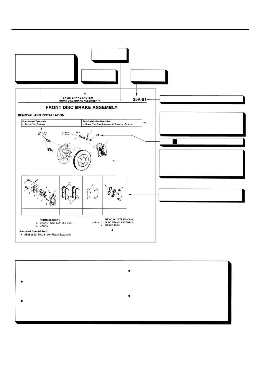
EXPLANATION OF MANUAL CONTENTS
N
Denotes tightening torque.
If there is no indication of
tightening torque, refer to
tightening torque.
Indicates the
group title.
Indicates the
section title.
Indicates the
group number.
Indicates the page number.
Indicates procedures to be performed be-
fore the work in that section is started, and
procedures to be performed after the work
in that section is finished.
Component diagram
A diagram of the component parts is pro-
vided near the front of each section in order
to give the reader a better understanding of
the installed condition of component parts.
Mark denotes non-reusable part.
Repair kit or parts sets are shown.
(Only very frequently used parts are shown.)
Removal steps :
The part designation number corresponds to
the number in the illustration to indicate removal
steps.
Disassembly steps :
The part designation number corresponds to
the number in the illustration to indicate dis-
assembly steps.
Maintenance and servicing procedures
The numbers provided within the diagram indicate the
sequence for maintenance and servicing procedures.
Installation steps :
Specified in case installation is impossible in
reverse order of removal steps. Omitted if
installation is possible in reverse order of
removal steps.
Assembly steps :
Specified in case installation is impossible in
reverse order of removal steps. Omitted if
assembly is possible in reverse order of
disassembly steps.
Brake caliper kit Pad set Shim kit Seal and boot kit
ZC6012870000
00-4
GENERAL <BODY AND CHASSIS>
HOW TO USE THIS MANUAL
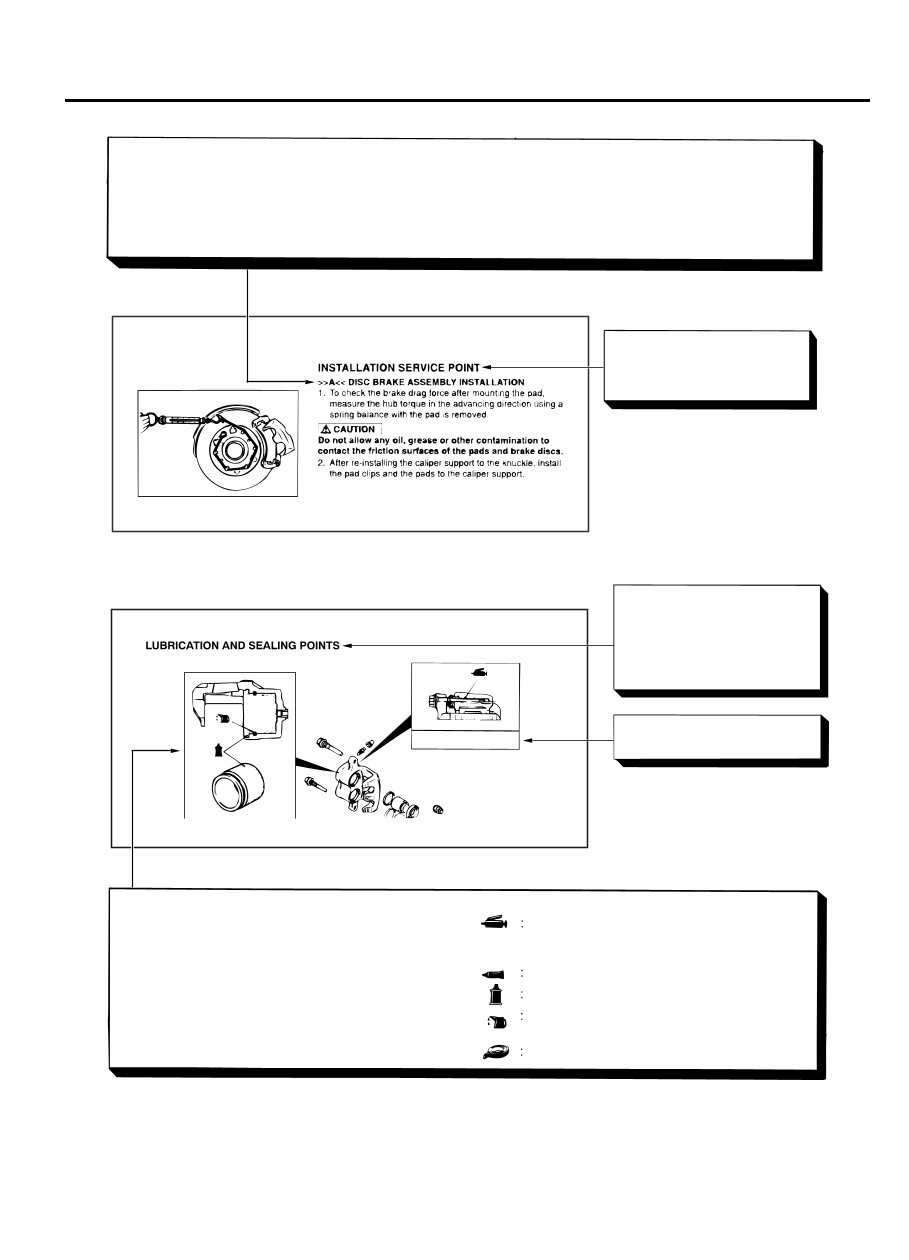
Classifications of major maintenance / service points
When there are major points relative to maintenance and servicing procedures (such as essential maintenance
and service points, maintenance and service standard values, information regarding the use of special tools, etc.).
These are arranged together as major maintenance and service points and explained in detail.
<<A>> : Indicates that there are essential points for removal or disassembly.
>>A<< : Indicates that there are essential points for installation or assembly.
Operating procedures,
cautions, etc. on removal,
installation, disassembly and
assembly are described
The title of the page
(following the page on which
the diagram of component
parts is presented) indicating
the locations of lubrication and
sealing procedures.
Indicates (by symbols) where
lubrication is necessary.
Symbols for lubrication, sealants and adhesives
Symbols are used to show the locations for lubrication
and for application of sealants and adhesives.
These symbols are included in the diagram of
component parts or on the page following the
component parts page. The symbols do not always
have accompanying text to support that symbol.
Adhesive tape or butyl rubber tape
Grease
(Multi-purpose grease unless there is a
brand or type specified)
Sealant or adhesive
Brake fluid or automatic transmission fluid
Engine oil, gear oil or air conditioning
compressor oil
Grease: repair kit grease
ZC6012880000
GENERAL <BODY AND CHASSIS>
00-5
HOW TO USE THIS MANUAL
You're Reading a Preview
What's Included?
 Lifetime Access
Fast Download Speeds
Offline Viewing
Access Contents & Bookmarks
Full Search Facility
Print one or all pages of your manual
$46.99
2005-2010 Mitsubishi Outlander Service & Repair Manual
Viewed 27 Times Today

What's Included?
Lifetime Access
Fast Download Speeds
Offline Viewing
Access Contents & Bookmarks
Full Search Facility
Print one or all pages of your manual
$46.99

Secure transaction
What's Included?
Lifetime Access
Fast Download Speeds
Offline Viewing
Access Contents & Bookmarks
Full Search Facility
Print one or all pages of your manual
Description
Fix your Mitsubishi Outlander yourself. This 2005-2010 service and repair manual walks you through every job, from routine maintenance to engine work, braking system overhauls, and electrical repairs. Step-by-step instructions, wiring diagrams, and exploded parts drawings make even complex procedures clear.
Download instantly and start your repair today. No subscriptions, no waiting. One purchase, lifetime access to the exact guidance you need for your Outlander.


