


0-1
GROUP 0
GENERAL
CONTENTS
MODELS . . . . . . . . . . . . . . . . . . . . . . 0-3
HOW TO READ THE WIRING
DIAGRAMS . . . . . . . . . . . . . . . . . . . . 0-4
COMPOSITION AND CONTENTS OF
WIRING DIAGRAMS. . . . . . . . . . . . . . . . . . 0-4
HOW TO READ CONFIGRATION
DIAGRAMS . . . . . . . . . . . . . . . . . . . . . . . . . 0-5
HOW TO READ CIRCUIT DIAGRAMS . . . . 0-6
MARKING FOR CONNECTOR AND
EARTHING . . . . . . . . . . . . . . . . . . . . . . . . . 0-8
WIRE COLOUR CODES . . . . . . . . . . . . . . . 0-11
ABBREVIATION SYMBOLS . . . . . . . . . . . . 0-11

NOTES
MODELS
GENERAL
0-3
MODELS
M3000000100500
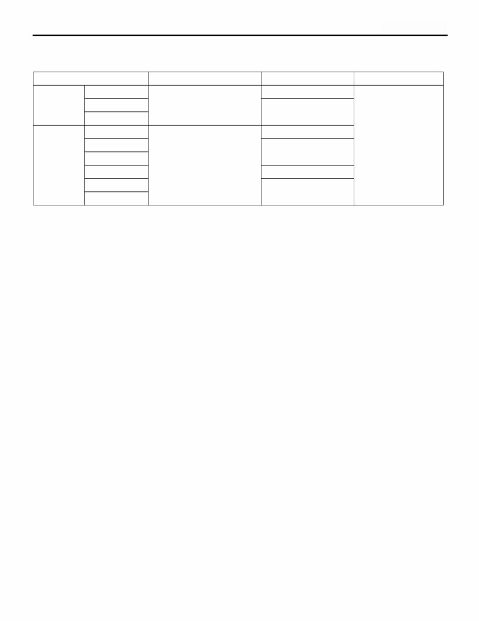
Model code Engine model Transmission model Fuel supply system
CU2W XNMML6 4G63-DOHC (1,997 mL) F5M42 <2WD-5M/T> MPI
XNMMZL6 W5M42 <4WD-5M/T>
XNHMZL6
CU5W XNMYZL6 4G69-SOHC (2,378 mL)
MIVEC
W5M42 <4WD-5M/T>
XRMYZL6 W4A4B <4WD-4A/T>
XRMYZR6
XNHYZL6 W5M42 <4WD-5M/T>
XRHYZL6 W4A4B <4WD-4A/T>
XRHYZR6

HOW TO READ THE WIRING DIAGRAMS
GENERAL
0-4
HOW TO READ THE WIRING DIAGRAMS
COMPOSITION AND CONTENTS OF
WIRING DIAGRAMS
M3000008000080
1. This manual consists of wiring harness diagrams, installation locations of individual parts, circuits
diagrams and index.
2. In each section, all specifications are listed, including optional specifications. Accordingly, some
specifications may not be applicable for individual vehicles.
Section Basic contents
Wiring harness
configuration
diagrams
Connector locations and harness wiring configurations on actual vehicles are
illustrated.
Single part
installation position
Locations are shown for each point of relays, electronic control units, sensors,
solenoids, solenoid valves, diodes, inspection connectors, spare connectors, fusible
links, fuses, etc. In the parts lists, parts are listed in alphabetical order.
Circuit diagrams Circuits from power supply to earth are shown completely, classified according to
system. There is a main division into power circuits and circuits classified by system.
The circuits classified by system also include operation and troubleshooting hints.
• Junction block
The entire circuit for the junction block is described, because only the part of the
junction block needed is normally shown in each circuit diagram.
• Joint connectors
The internal circuits for all joint connectors are described, because only the part
needed is shown in each circuit diagram.
• Power supply circuits
Circuits from the battery to fusible link, fuses, ignition switch, etc.
• Circuits classified by system
For each system, the circuits are shown from fuse to earth, excluding the power
supply sections.
• Operation
The standard operation of each system is briefly described, following the route of
current flow.
• Troubleshooting hints
This is a brief explanation of the inspection points that serve as hints when
troubleshooting. Explanations of the circuits controlled by the electronic control
unit are omitted. Refer to the related publications as required.
Index All components used are listed by connector number and component name.
HOW TO READ THE WIRING DIAGRAMS
GENERAL
0-5
HOW TO READ CONFIGRATION
DIAGRAMS
M3000009000102
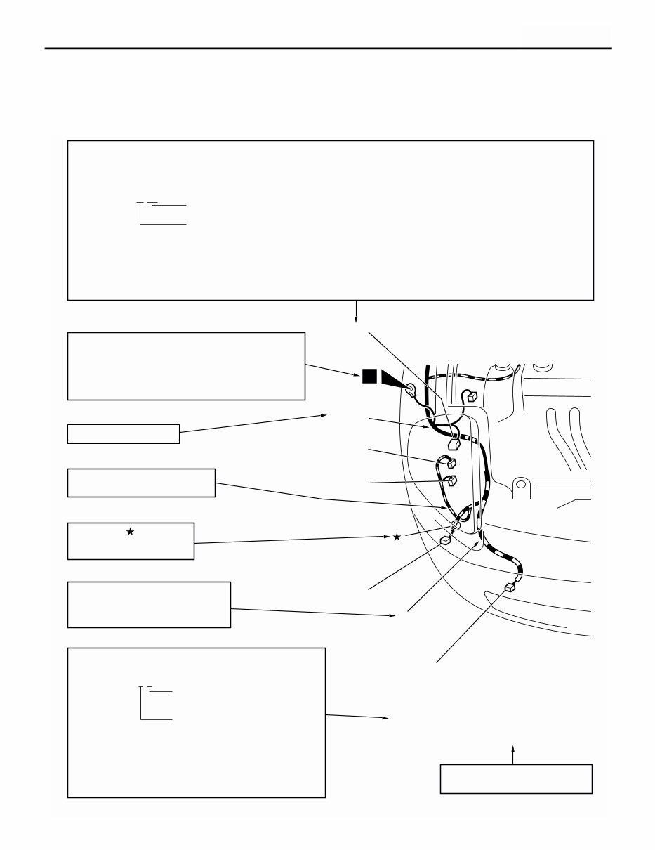
The wiring harness diagrams clearly show the connector locations and harness routings at each site on
actual vehicles.
AC208446
Denotes connector No.
The same connector No. is used throughout the circuit diagrams to facilitate connector location searches.
The first alphabetical symbol indicates the location site of the connector and a number that follows is the unique number.
Numbers are usually assigned to parts in clockwise order on the diagram.
Example: A-19
Number specific to connector (serial number)
Connector location site symbol
A: Engine compartment
B: Engine and transmission
C: Dash panel
D: Floor and roof
E: Door
F: Tailgate
Denotes earth point.
Same earth number is used throughout circuit
diagrams to facilitate search of earth point.
Refer to GROUP 2 SINGLE PART INSTALLATION
POSITION - EARTH MOUNTING LOCATIONS
for details of earth points.
Denotes the colour of the corrugated
tube (If not specified, it is black.)
R: Red
Y: Yellow
The number of connector pins and the connector colour
(except milk white)* are shown for ease of retrieval.
Example: (2-B)
Connector colour
(milk white if no colour is indicated)
Number of connector pins
*: Typical connector colours
B: Black BR: Brown
Y: Yellow V: Violet
L: Blue O: Orange
G: Green GR: Gray
R: Red None: Milk white
A-15 (2) Fog lamp (RH)
A-16 (2-GR) Horn (LO)
A-17 (2-B) Headlamp (RH)
A-18 (2-B) Windshield washer motor
A-19 (2-GR) Dual pressure switch
Indicates the device to which the
connector is connected.
The mark shows the
standard mounting position
of wiring harness.
AB
A-17
A-16
A-15
A-18
A-19
Y
Denotes a section covered by a
corrugated tube.
Front
wiring
harness
(RH)
Denotes harness name.
1
You're Reading a Preview
What's Included?
Fast Download Speeds
Offline Viewing
Access Contents & Bookmarks
Full Search Facility
Print one or all pages of your manual
$31.99
2003-2008 Mitsubishi Outlander Service & Repair Manual
Viewed 52 Times Today

What's Included?
Fast Download Speeds
Offline Viewing
Access Contents & Bookmarks
Full Search Facility
Print one or all pages of your manual
$31.99

Secure transaction
What's Included?
Fast Download Speeds
Offline Viewing
Access Contents & Bookmarks
Full Search Facility
Print one or all pages of your manual
Description
This 2003-2008 Mitsubishi Outlander Service & Repair Manual offers a comprehensive resource for both professional mechanics and DIY enthusiasts. Featuring high-quality diagrams and detailed repair instructions, this manual covers a diverse range of topics essential for proper vehicle maintenance and service.
- General
- Engine
- Engine Lubrication
- Fuel
- Engine Cooling
- Intake & Exhaust
- Engine & Emission Control
- Clutch
- Manual Transaxle
- Propeller Shaft
- Front Axle
- Rear Axle
- Wheel & Tire
- Power Plant Mount
- Front Suspension
- Rear Suspension
- Service Brakes
- Parking Brakes
- Steering
- Body
- Exterior
- Interior and Supplemental Restraint System
- Chassis Electrical
- Heater/A-C & Ventilation
This manual is provided in a printable file format compatible with all versions of Windows and Mac. Instantly accessible and easy to view using Adobe Reader, it serves as a valuable reference tool for all your repair and service needs.


