1997-2002 Mitsubishi Mirage Service Repair manual
Have a question?Ask Us
What's Included?
Fast Download Speeds
Offline Viewing
Access Contents & Bookmarks
Full Search Facility
Print one or all pages of your manual
00-1
GENERAL
CONTENTS 001 09000904
GENERAL <BODY AND CHASSIS> . . .. . . ... . . . ... ...... .. .. . . .. 00
GENERAL <ELECTRICAL> . . . . . . . . . . . . . . . ... . .. . . . .. . . . . . . . .. . . OOE
00-2
GENERAL
<BODY AND
CHASSIS>
CONTENTS M)109001172
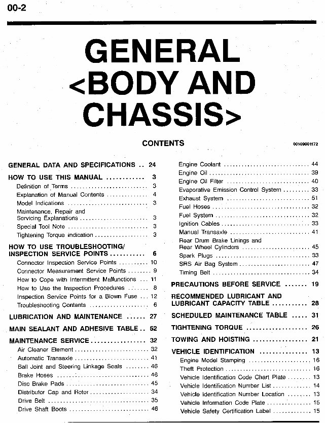
GENERAL DATA AND SPECIFICATIONS .. 24 Engine Coolant ............................. 44
HOW TO USE THIS MANUAL ............ 3
Definition of Terms .......................... 3
Explanation of Manual Contents .............. 4
Model Indications ........................... 3
Maintenance. Repair and
Servicing Explanations ....................... 3
Tightening Torque Indication .................. 3
HOW TO USE TROUBLESHOOTING/
INSPECTION SERVICE POINTS ........... 6
Connector Inspection Service Points .......... 10
Connector Measurement Service Points ........ 9
Special Tool Note ........................... 3
Engine Oil .................................. 39
Engine Oil Filter ............................ 40
Evaporative Emission Control System ......... 33
Exhaust System ............................ 51
Fuel Hoses ................................. 32
Fuel System ................................ 32
Ignition Cables .............................. 33
Manual Transaxle ........................... 41
Rear Drum Brake Linings and
Rear Wheel Cylinders ....................... 45
SRS Air Bag System ........................ 47
Timing Belt ................................. 34
Spark Plugs ................................ 33
How to Cope with Intermittent Malfunctions ... 11
How to Use the Inspection Procedures ....... 8
PRECAUTIONS BEFORE SERVICE ....... 19
Inspection Service Points for a Blown Fuse ... 12
RECOMMENDED LUBRICANT AND
Troubleshooting Contents .................... 6 LUBRICANT CAPACITY TABLE ........... 28
LUBRICATION AND MAINTENANCE ...... 27 SCHEDULED MAINTENANCE TABLE ..... 31
MAINTENANCE SERVICE ................. 32 TOWING AND HOISTING ................. 21
MAIN SEALANT AND ADHESIVE TABLE .. 52 TIGHTENING TORQUE ................... 26
Air Cleaner Element ......................... 32
Automatic Transaxle ......................... 41
Ball Joint and Steering Linkage Seals ........ 46
Brake Hoses ............................... 46
Disc Brake Pads ............................ 45
Distributor Cap and Rotor .................... 34
Drive Belt .................................. 35
Drive Shaft Boots ........................... 46
VEHICLE IDENTIFICATION ............... 13
Engine Model Stamping ..................... 16
Theft Protection ............................. 16
Vehicle Identification Code Chart Plate ........ 13
Vehicle Identification Number List ............. 14
Vehicle Identification Number Location ........ 13
Vehicle Information Code Plate ............... 15
Vehicle Safety Certification Label ............. 15
GENERAL - How to Use This Manual 00-3
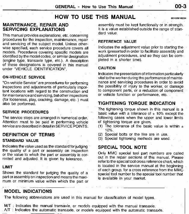
MAINTENANCE, REPAIR AND
SERVlC I NG EXPLAN AT1 0 N S
This manual providesexplanations,etc. concerning
procedures for the inspection, maintenance,repair
and servicing of the subject model. Unless other-
wise specified, each service procedure covers all
models. Procedures covering specific models are
identified by the modelcodes, or similar designation
(engine type, transaxle type, etc.). A description
of these designations is covered in this manual
under “VE H I C LE I DENT I F I CAT I 0 N ” .
ON-VEHICLE SERVICE
“On-vehicle Service” are proceduresfor performing
inspections and adjustments of particularly impor-
tant locations with regard to the construction and
for maintenance and servicing, but other inspections
(for looseness, play, cracking, damage, etc. ) must
also be performed.
SERVICE PROCEDURES
The service steps are arranged in numericalorder.
Attention must to be paid in performing vehicle
serviceare describedin detail in SERVICE POINTS.
DEFINITION OF TERMS
STANDARD VALUE
Indicatesthe value usedas the standardfor judging
the quality of a part or assembly on inspection
or the value to which the part or assembly is cor-
rected and adjusted. It is given by tolerance.
LIMIT
Shows the standard for judging the quality of a
part or assemblyon inspectionand meansthe maxi-
mum or minimum value within which the part or
HOW TO USE THIS MANUAL 001 0001 0234
assembly must be kept functionally or in strength.
It is a value established outside the range of stan-
dard value.
REFERENCE VALUE
Indicates the adjustment value prior to starting the
work (presentedin order to facilitate assembly and
adjustment procedures, and so they can be com-
pleted in a shorter time).
CAUTION
Indicates the presentation of information particularly
vital to the worker duringthe performance of mainte-
nance and servicing procedures in order to avoid
the possibility of injury to the worker, or damage
to component parts, or a reduction of component
or vehicle function or performance, etc.
TIGHTENING TORQUE INDICATION
The tightening torque shown in this manual is a
basic value with a tolerance of -c 10% except the
following cases when the upper and lower limits
of tightening torque are given.
(1) The tolerance of the basic value is within f
10%.
(2) Special bolts or the like are in use.
(3) Special tightening methods are used.
SPECIAL TOOL NOTE
Only MMC special tool part numbers are called
out in the repair sections of this manual. Please
refer to the special tool cross referencechart, which
is located in the service manual at the beginning
of each group, for a cross referencefrom the MMC
special tool number to the special tool number that
is available in your market.
M 0 D EL INDlCATlONS
The following abbreviations are used in this manual for classification of model types.
M/T : Indicates the manual transaxle, or models equipped with the manual transaxle.
Indicates the automatic transaxle, or models equipped with the automatic transaxle.
-_____
00-4 GENERAL - How to Use This Manual
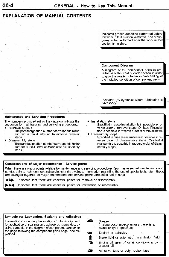
EXPLANATION OF MANUAL CONTENTS
Maintenance and Servicing Procedures
The numbers provided within the diagram indicate the
sequence for maintenance and servicing procedures.
0 Removal steps .
The part designation number corresponds to the
number in the illustration to indicate removal 0
steps
The part designation number corresponds to the
number in the illustration to indicate disassembly
steps.
0
0 Disassembly steps :
the work in that section is started, and proce-
section is finished.
A diagram of the component parts is pro-
to give the reader a better understanding of
the installed condition of component parts.
necessary.
I
Installation steps :
Specified in case installation is impossible in re-
verse order of removal steps Omitted if installa-
tion is possible in reverse order of removal steps
Specified in case reassembly is impossible in re-
verse order of disassembly steps Omitted if
reassembly is possible in reverse order of disas-
sembly steps
Reassembly steps
Classifications of Major Maintenance / Service points
When there are major points relative to maintenance and servicing procedures (such as essential maintenance and
service points, maintenance and service standard values, information regarding the use of special tools, etc ), these
are arranged together as major maintenance and service points and explained in detail
4Ab ' Indicates that there are essential points for removal or disassembly.
FA4 : Indicates that there are essential points for installation or reassembly.
-
Symbols for Lubrication, Sealants and Adhesives
Information concerningthe locations for lubrication and 6 : Grease
for application of sealants and adhesives is provided, by
using symbols, in the diagram of component parts or on
the page following the component parts page, and ex-
plained.
(multipurpose grease unless there is a
brand or type specified)
: Sealant or adhesive
: Brake fluid or automatic transmission fluid
pressor oil
:a : Engine oil, gear oil or air conditioning com-
a : Adhesive tape or butyl rubber tape
GENERAL - How to Use This Manual
Terminal
1 3 4 5
Battery voltage
Power is not supplied *4
Power is supplied 0 - 0 -+
__
00-5
0-0 indicates that there is
continuity between the termi-
nals.
0-0 indicates terminals to
which battery voltage is applied
FI
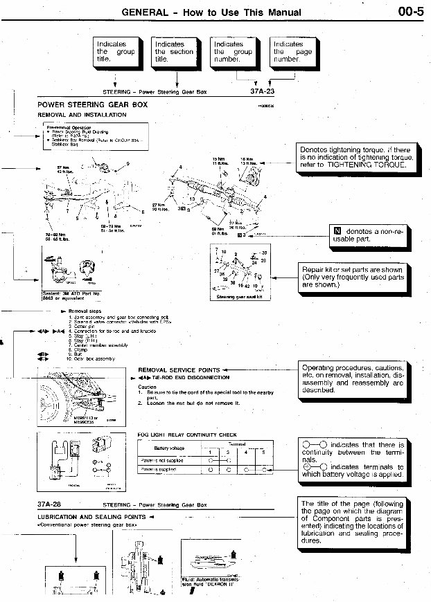
the group the section the group
STEERING - Power Steering Gear Box 37A-23
POWER STEERING GEAR BOX
REMOVAL AND INSTALLATION
15h 18Nm
.
D Removal sleps
1 Joint assembly and gear box connecting bolt
2 Solenoid valve wnnector <Vehicles with EPS>
3 Cotter p ~ n
4 Connection tor tie-rod end and knuckle
5 Stay (LH)
6 Slay (R H )
7 Center member assemblv
Repair kit or set parts are shown.
(Only very frequently used parts
I are shown.)

00-6 GENERAL - How to Use Troubleshooting/lnspection Service Points
HOW TO USE TROUBLESHOOTING/INSPECTlON SERVICE POINTS
00100020121
Troubleshootingof electronic control systems for which the scan tool can be used follows the basic outline
described below. Furthermore, even in systems for which the scan tool cannot be used, part of these
systems still follow this outline.
TROUBLESHOOTING CONTENTS
1.
2.
3.
4.
5.
6.
7.
8.
9.
STANDARD FLOW OF DIAGNOSTIC TROUBLESHOOTING
The main procedures for diagnostic troubleshooting are shown.
SYSTEM OPERATION AND SYMPTOM VERIFICATION TESTS
If verification of the trouble symptoms is difficult, procedures for checking operation and verifying
trouble symptoms are shown.
DIAGNOSTIC FUNCTION
The following diagnostic functions are shown.
0
0
0 Input inspection service points
INSPECTION CHART FOR DIAGNOSTIC TROUBLE CODES
INSPECTION PROCEDURE FOR DIAGNOSTIC TROUBLE CODES
Indicates the inspection procedures corresponding to each diagnostic trouble code. (Refer to the
next page on how to read the inspection procedures.)
INSPECTION CHART FOR TROUBLE SYMPTOMS
If there are trouble symptoms, even though the results of inspection using the scan tool show that
all diagnostic trouble codes are normal, inspection proceduresfor each trouble symptom will be found
by means of this chart.
INSPECTION PROCEDURE FOR DIAGNOSTIC SYMPTOM
Indicatesthe inspection procedurescorresponding to each trouble symptoms classified in the Inspection
Chart for Trouble Symptoms. (Refer to the next page on how to read the inspection procedures.)
SERVICE DATA REFERENCE TABLE
Inspectionitems and normaljudgementvalues have been providedin this chart as referenceinformation.
CHECK AT ECU TERMINALS
Terminal numbers for the ECU connectors, inspection items and standard values have been provided
in this chart as reference information.
Terminal Voltage Checks
Method of reading diagnostic trouble codes
Method of erasing diagnostic trouble codes
Connect a needle-nosed wire probe or paper clip to a voltmeter probe.
Insert the needle-nosed wire probe into each of the ECU connector terminals from the wire side,
and measure the voltage while referring to the check chart.
NOTE
1. Measure voltage with the ECU connectors connected.
2. You may find it convenient to pull out the ECU to make it easier to reach the connector
terminals.
3. Checks don’t have to be carried out in the order given in the chart.
Caution
Short-circuiting the positive (+) probe betweena connectorterminal and ground could damage
the vehicle wiring, the sensor, the ECU, or all three.
Use care to prevent this !
If voltage readings differ from Normal Condition values, check related sensors, actuators, and
wiring, then replace or repair.
GENERAL - How to Use Troubleshooting/lnspection Service Points 00-7
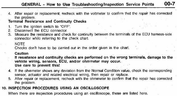
4. After repair or replacement, recheck with the voltmeter to confirm that the repair has corrected
the problem.
Terminal Resistance and Continuity Checks
1.
2.
3.
4.
5.
Turn the ignition switch to “OFF.
Disconnect the ECU connector.
Measure the resistance and check for continuity between the terminals of the ECU harness-side
connector while referring to the check chart.
NOTE
Checks don’t have to be carried out in the order given in the chart.
Caution
If resistance and continuity checks are performed on the wrong terminals, damage to the
vehicle wiring, sensors, ECU, and/or ohmmeter may occur.
Use care to prevent this!
If the ohmmeter shows any deviation from the Normal Condition value, check the corresponding
sensor, actuator and related electrical wiring, then repair or replace.
After repair or replacement, recheck with the ohmmeter to confirm that the repair has corrected
the problem.
’
10. INSPECTION PROCEDURES USING AN OSCILLOSCOPE
When there are inspection procedures using an oscilloscope, these are listed here.
00-8 GENERAL - How to Use Troubleshooting/lnspection Service Points
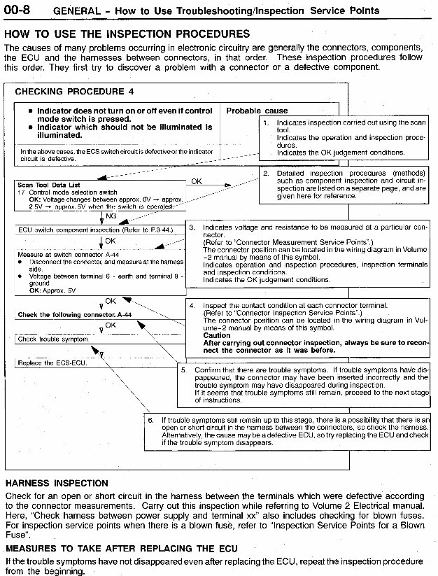
1 E~U switch component (Refer to p3-44 )
/
Measure at switch connector A-44
Disconnect the connector, and at the harness
side
0 Voltage between terminal 6 - earth and terminal 8 -
ground
0K:Approx 5V
4 OK
HOW TO USE THE INSPECTION PROCEDURES
3. Indicates voltage and resistance to be measured at a particular con-
nector.
(Refer to “Connector Measurement Service Points”.)
The connector position can be located in the wiring diagram in Volume
-2 manual by means of this symbol
Indicates operation and inspection procedures, inspection terminals
~ ~ ~ ~ ~ ~ ~ $ ~ ~ ~ ~ conditions
The causes of many problems occurring in electronic circuitry are generally the connectors, components,
the ECU and the harnesses between connectors, in that order. These inspection procedures follow
this order. They first try to discover a problem with a connector or a defective component.
CHECKING PROCEDURE 4
i°K \
4 OK
Check the following connector. A-44
-..,
~
I Check trouble symptom
I I
4 Inspect the contact condition at each connector terminal.
(Refer to “Connector Inspection Service Points”.)
The connector position can be located in the wiring diagram in Vol-
ume-2 manual by means of this symbol
Caution
After carrying out connector inspection, always be sure to recon-
nect the connector as it was before.
witch is pressed.
hich should not be illuminated is
tes the operation and inspection proce-
it is defective
1 Replace the ECS-ECU. \
\
I I
5. Confirm that there are trouble symptoms. If trouble symptoms have dis.
pappeared, the connector may have been inserted incorrectly and the
trouble symptom may have disappeared during inspection.
If it seems that trouble symptoms still remain, proceed to the next stage
of instructions.
I
6. If trouble symptoms still remain up to this stage, there is a possibility that there is ar
open or short circuit in the harness between the connectors, so check the harness.
Alternatively, the cause may be a defective ECU, so try replacingthe ECU and check
if the trouble symptom disappears.
HARNESS INSPECTION
Check for an open or short circuit in the harness between the terminals which were defective according
to the connector measurements. Carry out this inspection while referring to Volume 2 Electrical manual.
Here, “Check harness between power supply and terminal xx” also includes checking for blown fuses.
For inspection service points when there is a blown fuse, refer to “Inspection Service Points for a Blown
Fuse I’ .
MEASURES TO TAKE AFTER REPLACING THE ECU
If the trouble symptoms have not disappeared even after replacing the ECU, repeatthe inspection procedure
from the beginning.
GENERAL - How to Use Troubleshooting/lnspection Service Points 00-9
ooooo2 \
Inspection harness
for connector pin
contact pressure
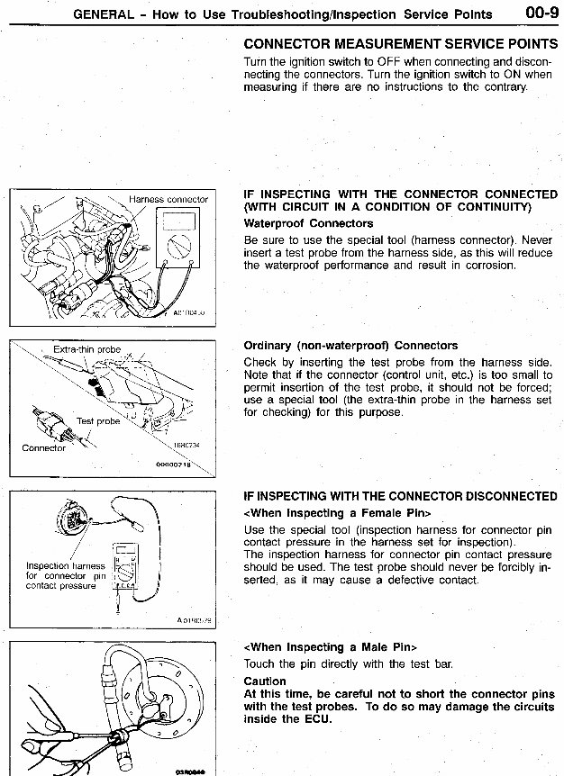
CONNECTOR MEASUREMENT SERVICE POINTS
Turn the ignition switch to OFF when connecting and discon-
necting the connectors. Turn the ignition switch to ON when
measuring if there are no instructions to the contrary.
IF INSPECTING WITH THE CONNECTOR CONNECTED
(WITH CIRCUIT IN A CONDITION OF CONTINUITY)
Waterproof Connectors
Be sure to use the special tool (harness connector). Never
insert a test probe from the harness side, as this will reduce
the waterproof performance and result in corrosion.
Ordinary (non-waterproof) Connectors
Check by inserting the test probe from the harness side.
Note that if the connector (control unit, etc.) is too small to
permit insertion of the test probe, it should not be forced;
use a special tool (the extra-thin probe in the harness set
for checking) for this purpose.
IF INSPECTING WITH THE CONNECTOR DISCONNECTED
<When Inspecting a Female Pin>
Use the special tool (inspection harness for connector pin
contact pressure in the harness set for inspection).
The inspection harness for connector pin contact pressure
should be used. The test probe should never be forcibly in-
serted, as it may cause a defective contact.
<When Inspecting a Male Pin>
Touch the pin directly with the test bar.
Caution
At this time, be careful not to short the connector pins
with the test probes. To do so may damage the circuits
inside the ECU.
00-1 0 GENERAL - How to Use Troubleshooting/lnspection Service Points
Connector disconnected or improperly
connected
16S0256
Defective connector contact
Harness wire breakage
at terminal section
Low contact pressure
1630254
000002 19
l6R1317
A 16U1318
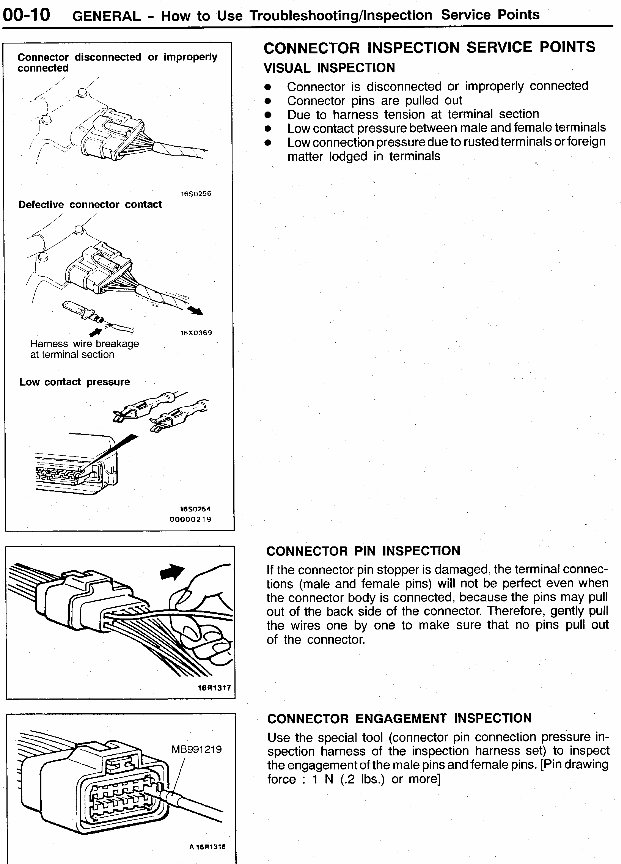
CONNECTOR INSPECTION SERVICE POINTS
VISUAL INSPECTION
0
0
0
0
Connector is disconnected or improperly connected
Connector pins are pulled out
Due to harness tension at terminal section
Low contact pressure betweenmale and female terminals
Low connectionpressuredue to rustedterminalsor foreign
matter lodged in terminals
CONNECTOR PIN INSPECTION
If the connector pin stopper is damaged, the terminal connec-
tions (male and female pins) will not be perfect even when
the connector body is connected, because the pins may pull
out of the back side of the connector. Therefore, gently pull
the wires one by one to make sure that no pins pull out
of the connector.
CONNECTOR ENGAGEMENT INSPECTION
Use the special tool (connector pin connection pressure in-
spection harness of the inspection harness set) to inspect
the engagement of the male pins andfemale pins. [Pin drawing
force : 1 N (.2 Ibs.) or more]
You're Reading a Preview
What's Included?
Fast Download Speeds
Offline Viewing
Access Contents & Bookmarks
Full Search Facility
Print one or all pages of your manual
$30.99
Viewed 17 Times Today


Secure transaction
What's Included?
Fast Download Speeds
Offline Viewing
Access Contents & Bookmarks
Full Search Facility
Print one or all pages of your manual
$30.99
You are purchasing a comprehensive 1997-2002 Mitsubishi Mirage Factory Service Workshop Manual. This manual is utilized by professional technicians at Mitsubishi dealerships to service and repair vehicles. It encompasses a wide range of services and repairs, from basic oil changes to intricate transmission rebuilds, making it ideal for both professional mechanics and DIY enthusiasts.
The manual covers an extensive list of sections, including but not limited to:
- Antilock brakes
- Bumpers
- Doors
- Keyless Entry
- Lightning system
- Disk brakes
- Park Brake
- Hydraulic Brake
- Front suspension
- Rear Suspension
- Interior Trim
- Exterior trim
- HVAC
- Engine Cooling
- Engine Exhaust
- Engine Electrical
- Engines Power Steering
- Roof and Sunroof
- SIR
- Steering wheel
- Transmission
- Wheel drive shaft
- Washer and wiper
The manual is available in .PDF format and is compatible with Win95/98/ME/XP/Vista/7, Linux, and MAC operating systems. It is a valuable resource for anyone working on or maintaining a 1997-2002 Mitsubishi Mirage.