POWER TRAIN – Clutch 2-2 CLUTCH <EVOLUTION-IV> A clutch with a pull-type diaphragm spring is utilized to enhance the disengagement characteristics and lighten the pedal action during high-speed operation. Specifications Drive system 4WD Engine 4G63 DOHC-T/C Control system Hydraulic Clutch disc type Dry; single Clutch disc size (mm) 230 150 Clutch cover type Diaphragm spring (pull-type) Clutch cover load setting (N {kgf}) 7,845 {800} Release cylinder size (mm) 20.6 Flexible flywheel No <EVOLUTION-V> The EVOLUTION-V’s clutch is basically the same as the EVOLUTION-IV’s clutch. In light of the engine’s higher torque, however, the clutch cover set load has been increased. Specifications Item EVOLUTION-IV EVOLUTION-V Clutch cover load setting (N {kgf}) 7,845 {800} 8,826 {900}
POWER TRAIN – Manual Transmission 2-3 MANUAL TRANSMISSION The W5M51 transmission has been newly adopted. Specifications Model W5M51 (Normal type) W5M51 (With super cross gear) Engine 4G63 DOHC-T/C Type Forward 5-speed, constant mesh Reverse One-speed, constant mesh Gear ratios (numbers of teeth) 1st 2.785 (39/14) (numbers of teeth) 2nd 1.960 (39/20) 3rd 1.407 (38/27) 1.444 (39/27) 4th 1.031 (33/32) 1.096 (34/31) 5th 0.761 (32/42) 0.825 (33/40) Reverse 3.416 (41/12) Final reduction ratio (numbers of teeth) 4.529 (77/17) 4.875 (78/16) or 4.529 (77/17) Transfer Reduction ratio (numbers of teeth) 1/3.312 (16/53) Limited-slip differential VCU Reverse synchromesh Yes Speedometer gear ratio 29/36 30/36 29/36 30/36 Front limited-slip differential Helical-gear type TRANSMISSION CONTROL The transmission control mechanism is basically the same as that of the previous model. However, the gear shift lever has a shorter stroke.
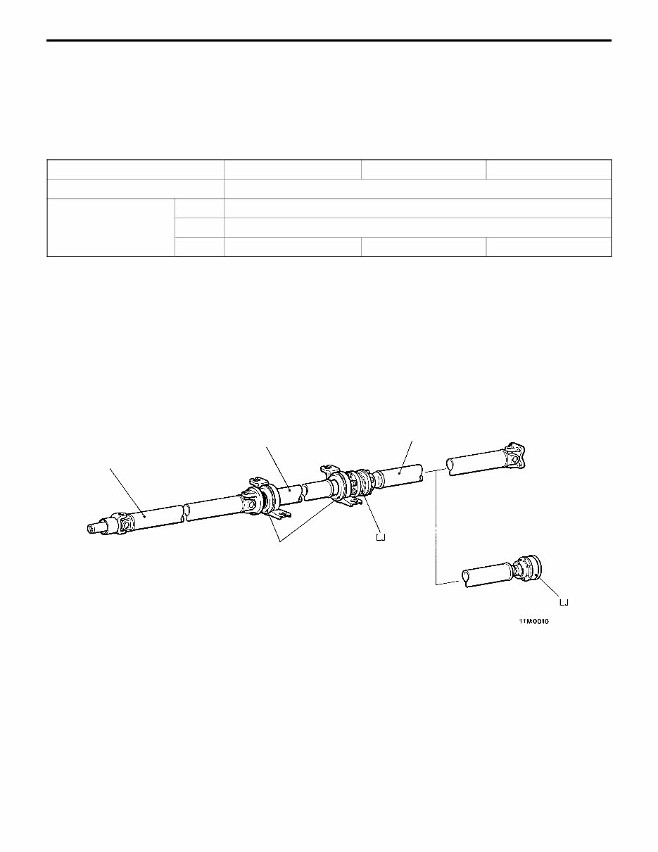
POWER TRAIN – Propeller Shafts 2-4 PROPELLER SHAFTS <EVOLUTION-IV> The propeller shafts are basically the same as those of EVOLUTION-III. However, the specifications of the rear propeller shaft have been revised as shown below. Specifications Item RS GSR EVOLUTION-III Type Three-joint; multi-part Length diameter mm Front 676.5 65 Center 505 65 Rear 666.5 65 (684.5 65) 684.5 65 666.5 65 NOTE: (1) The length of each propeller shaft is given as the distance between the centers of the joints. (2) Figures in parentheses apply to vehicles fitted with the AYC system. <EVOLUTION-V RS> The joint between the rear propeller shaft and the rear differential has been changed from a Löbro joint (LJ) to a Cardan universal joint. Front propeller shaft Center propeller shaft Rear propeller shaft <New> <Old> Center bearing
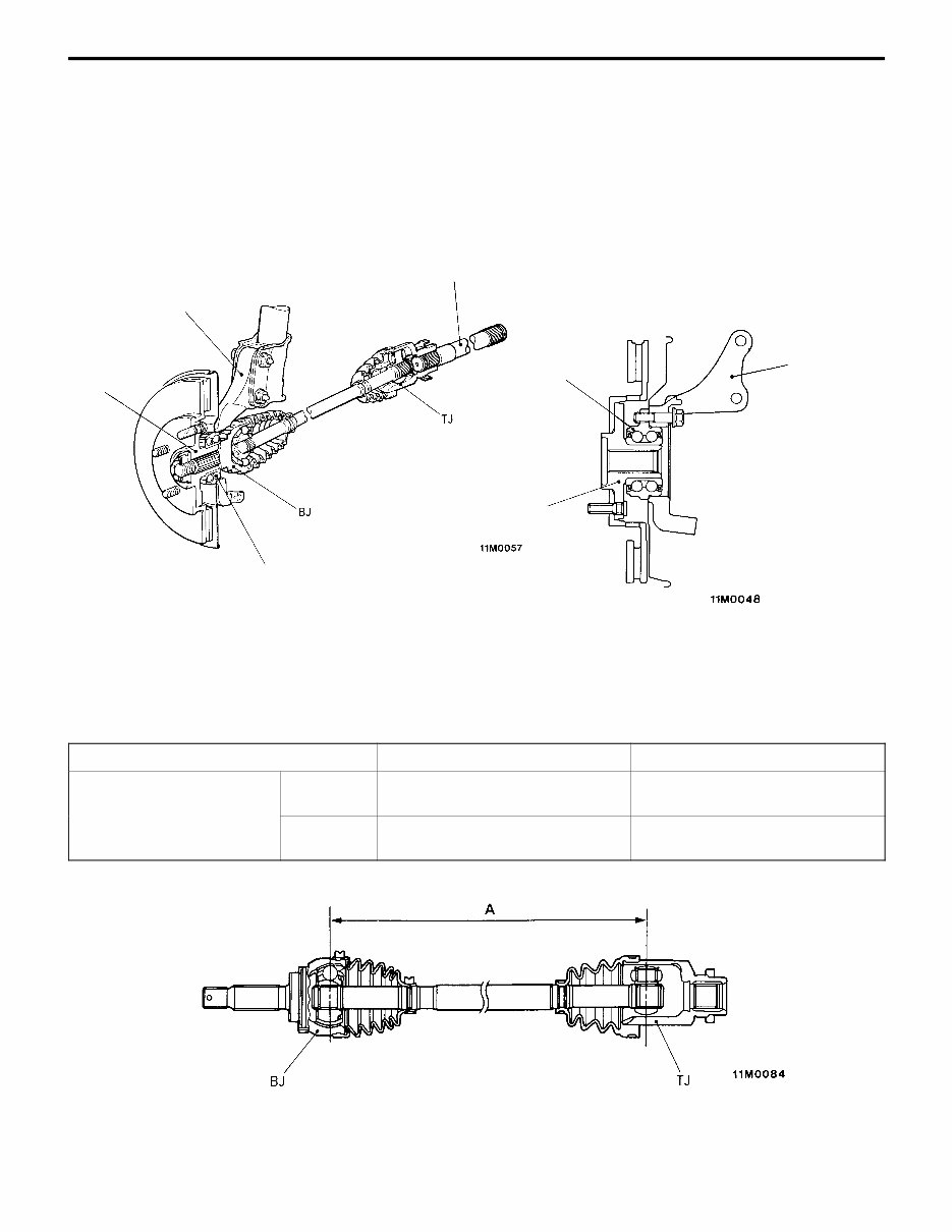
POWER TRAIN – Front Axle 2-5 FRONT AXLE To match the high-performance engine, the front axle has been revised as follows: D Unit ball bearings are used for the wheel bearings to enhance rigidity. D For easier maintenance, the wheel bearings are bolted onto the knuckles. D In light of the engine’s higher output, the number of hub bolts has been increased from four to five. Configuration Knuckle Front hub Output shaft Wheel bearing Wheel bearing Front hub Knuckle <EVOLUTION-V> DRIVE SHAFTS In accordance with the wider tread, the joint-to-joint distances (see dimension “A” in the drawing) have been increased as shown in the following table. Item EVOLUTION-IV EVOLUTION-V Joint-to-joint distance (mm) Right-hand side 418 442 Left-hand side 348 365
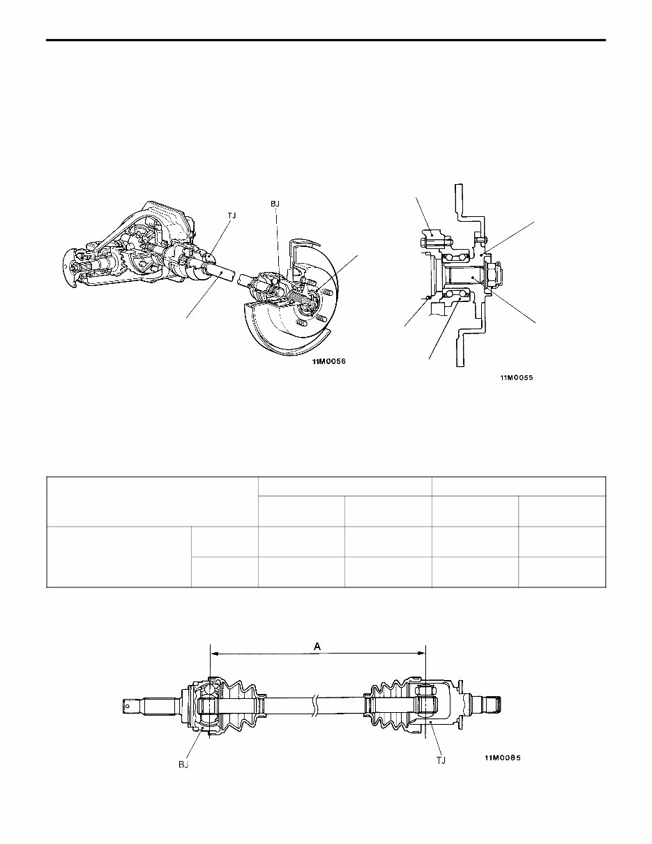
POWER TRAIN – Rear Axle 2-6 REAR AXLE To match the high-performance engine, the rear axle has been revised as follows: D For easier maintenance, the wheel bearings are bolted onto the knuckles. D In light of the engine’s higher output, the number of hub bolts has been increased from four to five. D On ABS-equipped vehicles, wheel speed sensor rotors are fitted on the drive shafts and wheel speed sensors are fitted on the knuckles. Configuration Drive shaft Rear hub Knuckle Rotor (ABS-equipped vehicles only) Wheel bearing Rear hub Drive shaft <EVOLUTION-V> DRIVE SHAFTS (1) In accordance with the wider tread, the joint-to-joint distances (see dimension “A” in the drawing) have been increased as shown in the following table. EVOLUTION-IV EVOLUTION-V Item Without AYC system With AYC system Without AYC system With AYC system Joint-to-joint distance (mm) Right-hand side 560 435 578 453 Left-hand side 480 425 498 443 (2) On the GSR model, the joints closer to the differential have been changed from the double-offset type (DOJ) to the tripod type (TJ). (On the RS model, tripod joints were already used.) (changed from DOJ on GSR model)
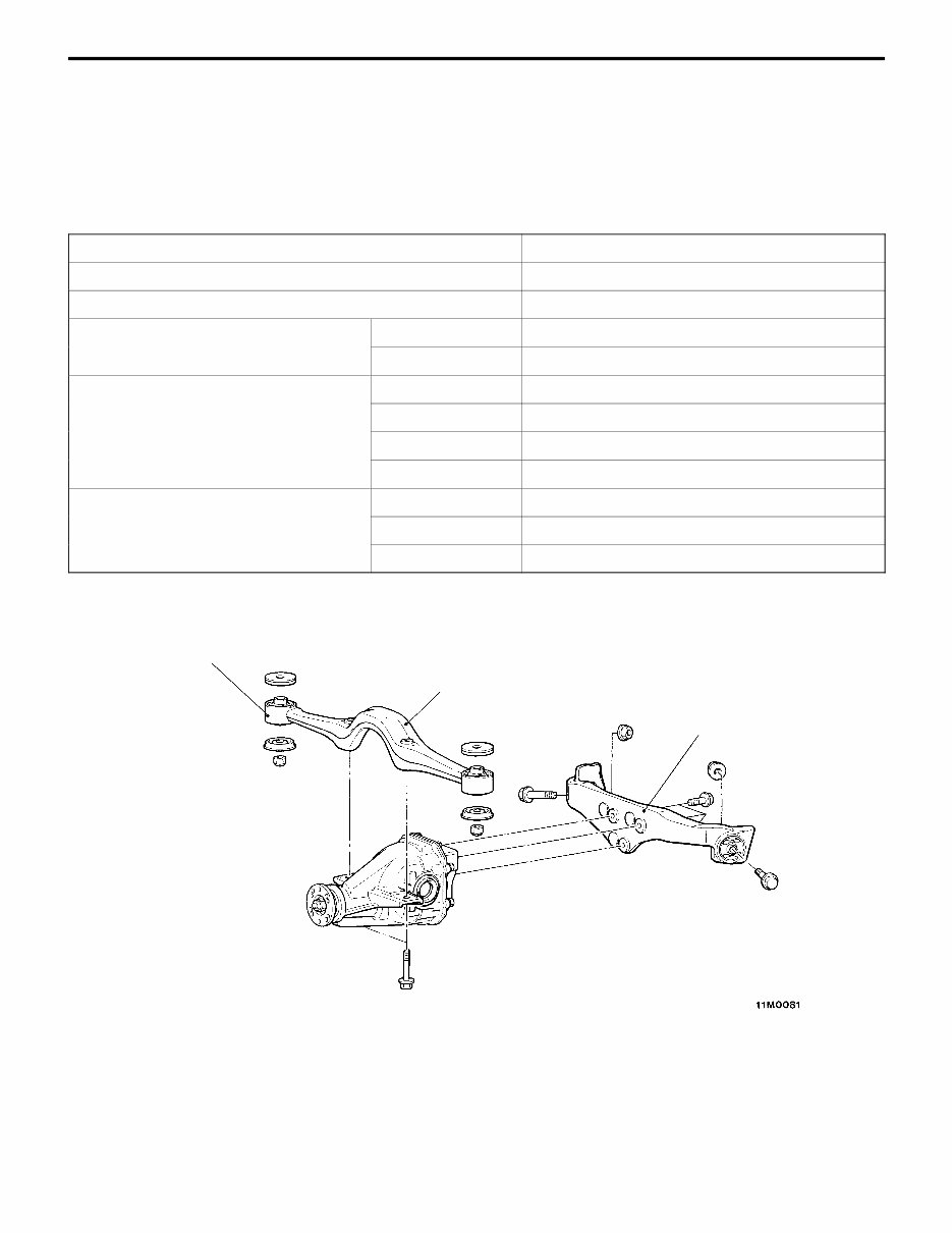
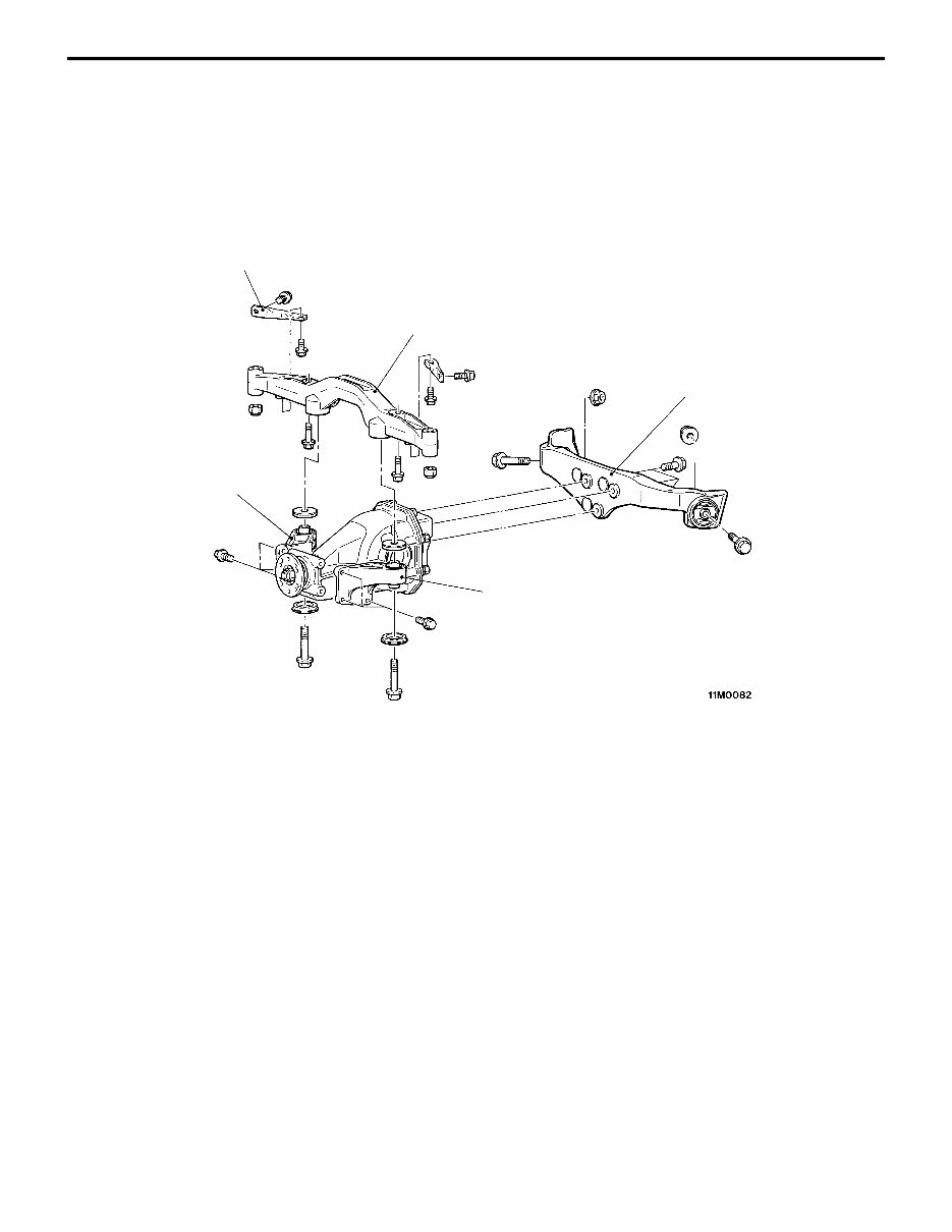
POWER TRAIN – Rear Axle 2-7 DIFFERENTIAL Vehicles without the AYC system are fitted with a mechanical LSD. The LSD is basically the same as that of the EVOLUTION-III. NOTE For details of the LSD fitted on vehicles with the AYC system, refer to page 2-14. Specifications Item Mechanical LSD Reduction gear type Hypoid gears Reduction ratio 3.312 Differential gear (type quantity) Side gear Straight bevel gear 2 Pinion gear Straight bevel gear 4 Number of teeth Drive gear 53 Drive pinion 16 Side gear 16 Pinion gear 10 Bearing (outside diameter inside di- ameter) (mm) Side 72 35 ameter) (mm) Front 62 25 Rear 72 35 <EVOLUTION-IV> Insulator Differential support member Differential support arm
POWER TRAIN – Rear Axle 2-8 <EVOLUTION-V RS> D The differential’s reduction gear ratio has been revised from 3.312 to 3.307. D The differential support member is joined to the body without insulators, yielding a stiff joint that enhances the body’s torsional rigidity. Also, the differential support member is made from cast aluminum for lightness. <EVOLUTION-V> Toe control bar Differential support member (cast aluminum) Differential support arm Differential mounting bracket Insulator
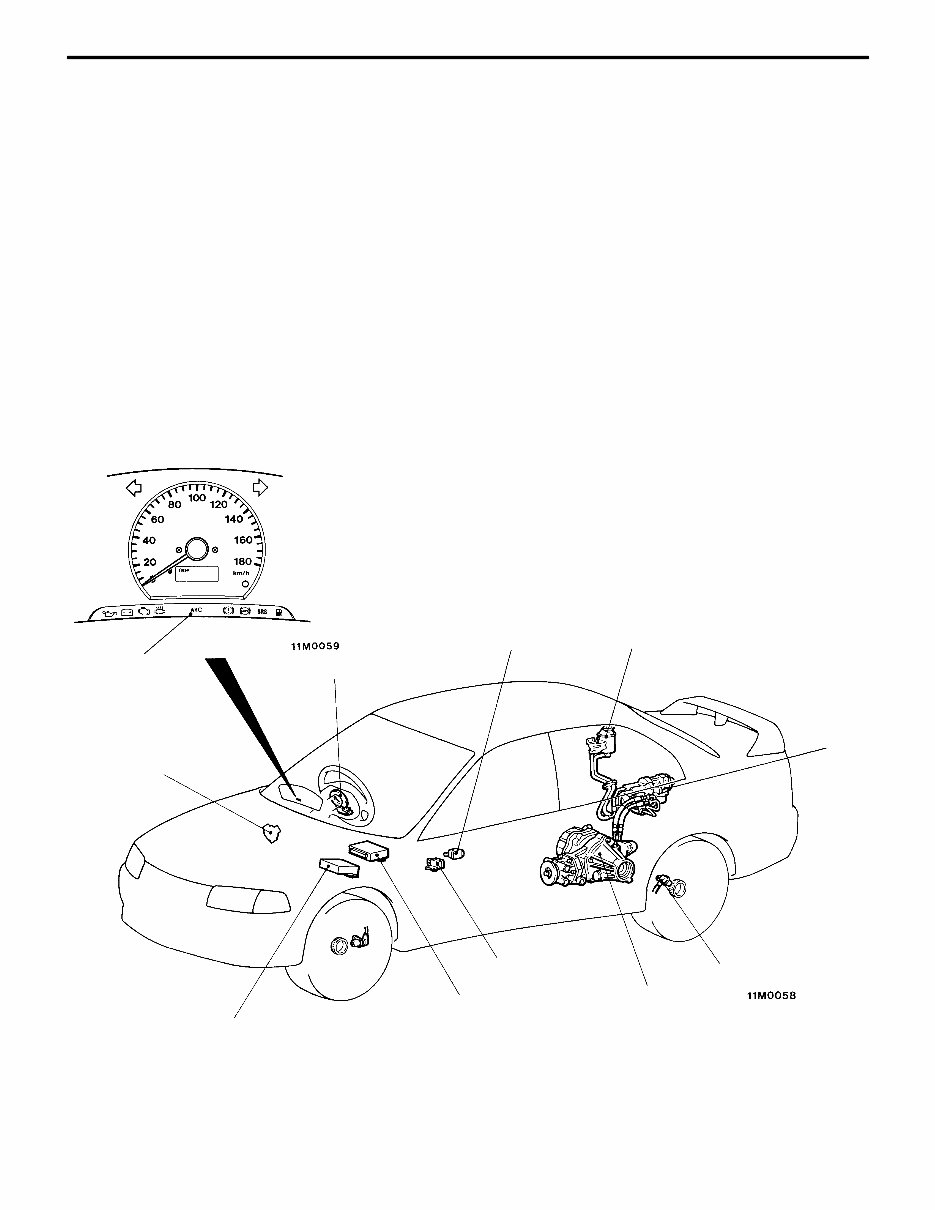
POWER TRAIN – AYC System 2-9 AYC SYSTEM The active yaw control (AYC) system is available with the EVOLUTION-IV <standard on GSR; optional on RS>. The system actively controls the difference in driving force between the left and right rear wheels, thereby adjusting the vehicle’s yaw moment such that all four tires perform to their maximum potential. As a result, safety is enhanced for all drivers. [World-Leading Technology] The AYC system incorporates a torque transfer differential. Newly developed by Mitsubishi Motors, this device allows torque to be transferred between the left and right wheels as required. [Maximized Safety] (1) Even when the vehicle is driven near the edge of its performance envelope, the AYC system ensures that it responds faithfully and naturally to the driver’s steering and accelerator inputs. Thus, controllability is optimized at all times. (2) By suppressing sudden changes in vehicle behavior during acceleration and deceleration, the AYC system provides superior stability. System Configuration AYC warning lamp Throttle position sensor Steering wheel sensor Lateral G sensor Reservoir tank Longitudinal G sensor Torque transfer differential Wheel speed sensor Hydraulic unit ABS-ECU AYC-ECU
POWER TRAIN – AYC System 2-10 Major Components Component Function Reference page AYC-ECU Calculates direction and magnitude of required torque transfers in accordance with data from sensors and switches, and controls hy- draulic unit accordingly 2-20 Controls diagnosis and fail-safe functions 2-22 ABS-ECU Monitors ABS operating status — Throttle position sensor Informs AYC-ECU when engine is idling 2-16 Provides AYC-ECU with data on throttle valve opening AYC warning lamp Illuminates in event of system failure (also illuminates for 1.5 se- conds when ignition switch is turned to ON position) 2-22 Stop lamp switch Provides AYC-ECU with data to enable evaluation of brake operat- ing status — Longitudinal G sensor Provides AYC-ECU with data on vehicle’s rate of longitudinal ac- celeration 2-16 Lateral G sensor Provides AYC-ECU with data on vehicle’s rate of lateral accelera- tion 2-16 Steering wheel sensor Provides AYC-ECU with data on steering wheel angle 2-16 Informs AYC-ECU when steering wheel is in straight-ahead posi- tion Wheel speed sensor (one on each wheel) Provides AYC-ECU with data on wheel speed 2-16 Hydraulic unit Hydraulic switch Provides AYC-ECU with data on accumulator pressure 2-17 unit Electric pump Produces hydraulic pressure for clutch actuation Direction control valve Determines whether hydraulic pressure is supplied to left-hand clutch or right-hand clutch Proportioning valve Controls supply of hydraulic pressure to clutches Electric pump relay Supplies power to electric pump — Torque transfer differential Apportions torque to driven wheels 2-14
The Mitsubishi Lancer Evolution IV, Evolution V, and Evolution VI (Evo 4, Evo 5, Evo 6) Workshop Service Repair Manual 1996-2001 is an essential resource for both professional mechanics and passionate enthusiasts. It covers the years 1996 to 2001, providing comprehensive guidance for maintaining and repairing all Evolution IV, Evolution V, and Evolution VI models.
This extensive manual comprises over 2,300 pages of detailed instructions, diagrams, and illustrations, making it the most comprehensive manual available for these iconic Mitsubishi models.
Inside the manual, you'll find step-by-step procedures for various repairs and maintenance tasks, from simple oil changes to complex engine overhauls. It also includes troubleshooting guides to help diagnose and resolve common issues with your Lancer Evolution.
Key features of the Mitsubishi Lancer Evolution IV, Evolution V, and Evolution VI Workshop Service Repair Manual include:
Complete coverage for all Evo 4, Evo 5, and Evo 6 models
Clear and concise instructions for every repair
Diagrams and illustrations for easy understanding
Detailed specifications and technical data
Troubleshooting guides for common problems
Maintenance schedules for optimal performance
Wiring diagrams for electrical systems
And much more!
With this Workshop Service Repair Manual, you'll have all the information you need to ensure your Mitsubishi Lancer Evolution runs smoothly. Take control of your vehicle's maintenance today and prevent minor issues from becoming major problems.
Recently Viewed
5,521,897Happy Clients
2,594,462eManuals
1,120,453Trusted Sellers
15Years in Business
Price:
Actual Price:
1996-2001 Mitsubishi Lancer Evolution IV, V, VI Service & Repair Manual

 Workshop Service Repair Manual 1996-2001 (2,300+")