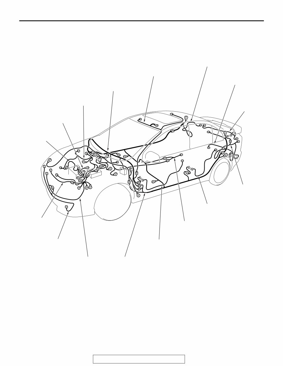
OVERALL CONFIGURATION DIAGRAM <LANCER (NON-TURBO)> TSB Revision CONFIGURATION DIAGRAMS 80A-2 OVERALL CONFIGURATION DIAGRAM <LANCER (NON-TURBO)> M1801000103450 ACA00186 AB Battery (+) wiring harness Battery (-) wiring harness Control wiring harness Instrument panel wiring harness Roof wiring harness Rear floor wiring harness (RH) Rear bumper wiring harness Trunk lid wiring harness Front impact sensor wiring harness Fog light wiring harness Front wiring harness Floor wiring harness Front door wiring harness* Console wiring harness Rear door wiring harness* Rear floor wiring harness (LH) NOTE: . 1. This illustration shows only major wiring harnesses. 2. *: also equipped at the right side.
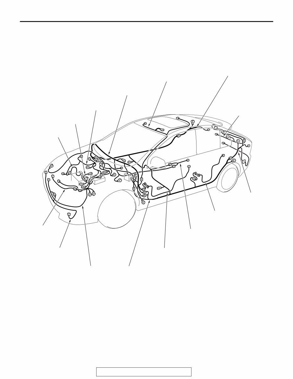
80A-3 OVERALL CONFIGURATION DIAGRAM <LANCER SPORTBACK (NON-TURBO)> TSB Revision CONFIGURATION DIAGRAMS OVERALL CONFIGURATION DIAGRAM <LANCER SPORTBACK (NON-TURBO)> M1801000103438 ACA00187 AB Battery (+) wiring harness Battery (-) wiring harness Control wiring harness Instrument panel wiring harness Roof wiring harness Rear floor wiring harness (RH) Liftgate wiring harness Front impact sensor wiring harness Fog light wiring harness Front wiring harness Floor wiring harness Front door wiring harness* Console wiring harness Rear door wiring harness* Rear floor wiring harness (LH) NOTE: . 1. This illustration shows only major wiring harnesses. 2. *: also equipped at the right side.
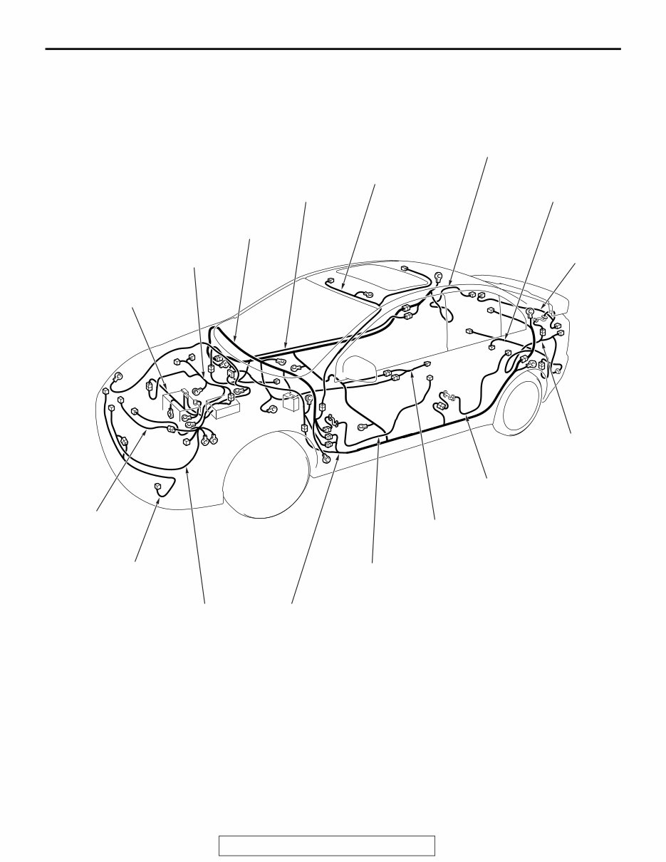
OVERALL CONFIGURATION DIAGRAM <LANCER (TURBO)> TSB Revision CONFIGURATION DIAGRAMS 80A-4 OVERALL CONFIGURATION DIAGRAM <LANCER (TURBO)> M1801000103461 AC901082 AB Battery wiring harness Control wiring harness Instrument panel wiring harness Front impact sensor wiring harness Fog light wiring harness Front wiring harness Floor wiring harness Front door wiring harness* Console wiring harness Rear door wiring harness* Roof wiring harness Rear floor wiring harness (RH) Rear bumper wiring harness Trunk lid wiring harness Rear floor wiring harness (LH) ACD power line wiring harness NOTE: . 1. This illustration shows only major wiring harnesses. 2. *: also equipped at the right side.
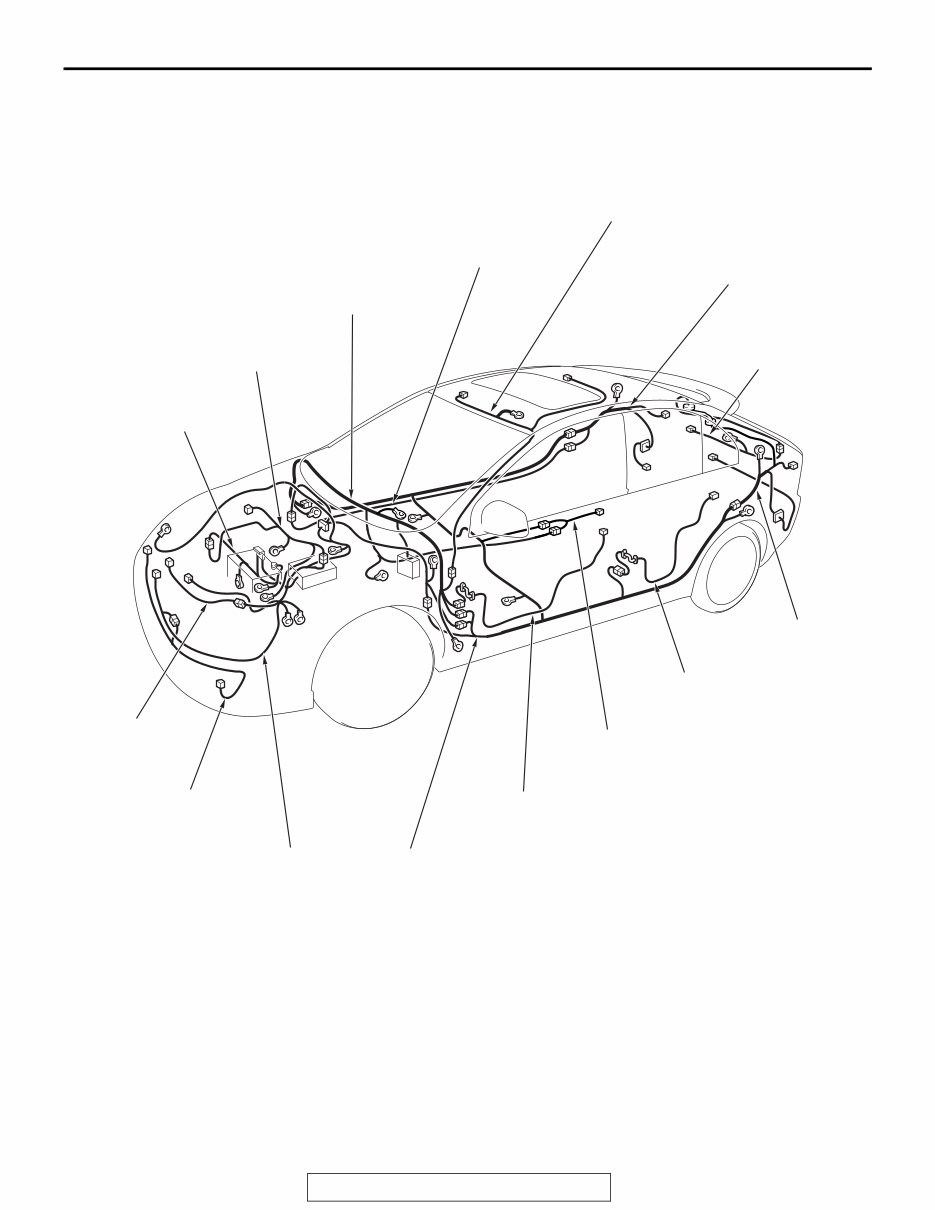
OVERALL CONFIGURATION DIAGRAM <LANCER SPORTBACK (TURBO)> TSB Revision CONFIGURATION DIAGRAMS 80A-5 OVERALL CONFIGURATION DIAGRAM <LANCER SPORTBACK (TURBO)> M1801000103449 AC807032 AB Battery wiring harness Control wiring harness Instrument panel wiring harness Roof wiring harness Rear floor wiring harness (RH) Liftgate wiring harness Front impact sensor wiring harness Fog light wiring harness Front wiring harness Floor wiring harness Front door wiring harness* Console wiring harness Rear door wiring harness* Rear floor wiring harness (LH) ACD power line wiring harness NOTE: . 1. This illustration shows only major wiring harnesses. 2. *: also equipped at the right side.
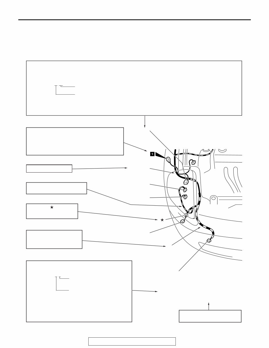
HOW TO READ CONFIGURATION DIAGRAMS TSB Revision CONFIGURATION DIAGRAMS 80A-6 HOW TO READ CONFIGURATION DIAGRAMS M1801000200696 The wiring harness diagrams clearly show the connector locations and harness configurations on actual vehi- cles. Some variations are included in one configuration diagram. Accordingly, some diagrams may not be applicable for individual vehicles. AC208446 Denotes connector No. The same connector No. is used throughout the circuit diagrams to facilitate connector location searches. The first alphabetical symbol indicates the location site of the connector and a number that follows is the unique number. Numbers are usually assigned to parts in clockwise order on the diagram. Example: A-19 Number specific to connector (serial number) Connector location site symbol A: ENGINE COMPARTMENT E: DOOR B: ENGINE AND TRANSAXLE F: LUGGAGE COMPARTMENT <LANCER> C: DASH PANEL F: LIFTGATE <LANCER SPORTBACK> D: FLOOR AND ROOF Denotes ground point. Same ground number is used throughout circuit diagrams to facilitate search of ground point. Refer to GROUP 70 COMPONENT LOCATIONS -GROUND MOUNTING LOCATIONS for details of ground points. Denotes the color of the tube (If not specified, it is black). R: Red Y: Yellow The number of connector pins and the connector color (except milk white)* are shown for ease of retrieval. Example: (2-B) Connector color (milk white if no color is indicated) Number of connector pins *: Typical connector colors B: Black BR: Brown Y: Yellow V: Violet L: Blue O: Orange G: Green GR: Gray R: Red None: Milk white A-15 (2) FOG LIGHT (RH) A-16 (2-GR) HORN (LOW) A-17 (2-B) HEADLIGHT (RH) A-18 (2-B) WINDSHIELD WASHER MOTOR A-19 (2-GR) DUAL PRESSURE SWITCH Indicates the device to which the connector is connected. The mark shows the standard mounting position of wiring harness. BE A-17 A-16 A-15 A-18 A-19 Y Denotes a section covered by a corrugated tube. FRONT WIRING HARNESS (RH) Denotes harness name.
HOW TO READ CONFIGURATION DIAGRAMS TSB Revision CONFIGURATION DIAGRAMS 80A-7 NOTES
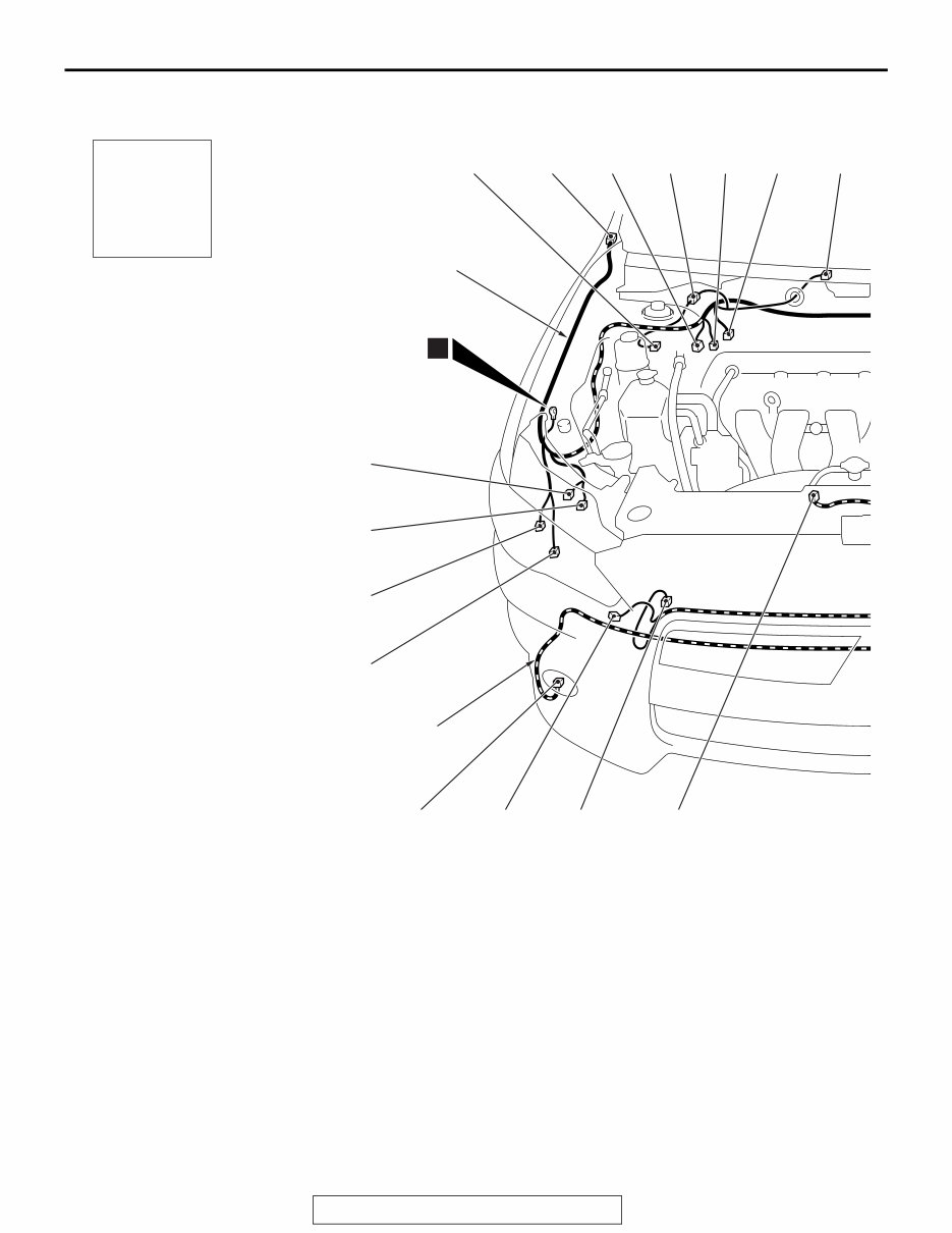
ENGINE COMPARTMENT <NON-TURBO> TSB Revision CONFIGURATION DIAGRAMS 80A-8 ENGINE COMPARTMENT <NON-TURBO> M1801000307434 ACA00197 Connector symbol A AB A-01 A-62 A-48 A-02 A-03 A-51 A-04 Connector color code B: Black BR: Brown G: Green GR: Gray L: Blue None: Milk white O: Orange R: Red V: Violet Y: Yellow A-44 A-43 A-42 A-41 A-47 A-50 A-46 A-45 1 Front wiring harness Fog light wiring harness A-63 A-01 (2-B) Side turn-signal light (RH) A-02 (2-B) Front wheel speed sensor (RH) A-03 (26-B) ABS-ECU A-04 (5-GR) Windshield wiper motor A-05 (4-GR) Mass airflow sensor A-06 (2-B) Brake fluid level switch A-07 (2-B) Front wheel speed sensor (LH) A-08 (2-B) Side turn-signal light (LH) A-09 (24) Front wiring harness and control wiring harness combination <CVT> A-10 (20) Front wiring harness and control wiring harness combination A-11X (4) Fog light relay A-12X (4) Horn relay A-13X (4) A/C compressor clutch relay A-14X (4) No connection A-15X (4) CVT control relay A-16X (4) No connection A-17X (4) Headlight relay (High) A-18X (4) Throttle actuator control motor relay A-20X (4) Daytime running light relay <Vehicles with discharge type headlight> A-21X (4) Injector relay A-23X (4) Condenser fan relay A-24X (4) Starter relay A-25X (4) Headlight relay (Low) A-26X (4) Radiator fan relay A-28X (4) Fan control relay A-30X (4) MFI relay A-31 (12-B) Headlight assembly (LH)
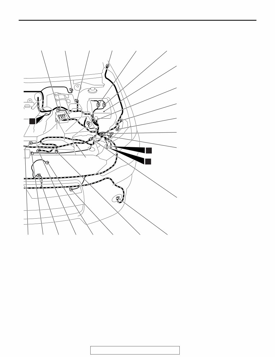
ACA00198 AB A-05 A-06 A-07 A-08 A-09 A-10 A-33 A-34 A-39 A-65 A-38 A-37 A-35 A-36 16 18 Front impact sensor wiring harness 17 A-40 A-31 A-52 A-64 A-49 A-32 A-11X A-12X A-13X A-14X A-15X A-16X A-17X A-18X A-20X A-21X A-23X A-24X A-25X A-26X A-28X A-30X A-32 (6-B) Headlight assembly (LH) A-33 (4-B) Front wiring harness and front impact sensor wiring harness combination A-34 (2-B) Fog light (LH) A-35 (2-GR) Radiator fan motor A-36 (2-B) Ambient temperature sensor A-37 (1-B) Horn (Low) A-38 (2-Y) Front impact sensor (LH) A-39 (2-B) Front wiring harness and fog light wiring harness combination A-40 (2-B) Condenser fan motor A-41 (2-Y) Front impact sensor (RH) A-42 (3-B) A/C pressure sensor A-43 (1-B) Horn (High) A-44 (2-B) Fog light (RH) A-45 (2-B) Washer motor A-46 (6-B) Headlight assembly (RH) A-47 (12-B) Headlight assembly (RH) A-48 (3-GR) No connection A-49 (1-GR) No connection A-50 (2-B) No connection A-51 (47-B) ASC-ECU A-52 (2-B) No connection A-62 (4-B) Theft-alarm siren A-63 (4-B) Front wiring harness and theft-alarm siren sub wiring harness combination A-64 (4-GR) Battery current sensor A-65 (2-B) Hood latch switch <Vehicles with theft-alarm sensor> ENGINE COMPARTMENT <NON-TURBO> TSB Revision CONFIGURATION DIAGRAMS 80A-9
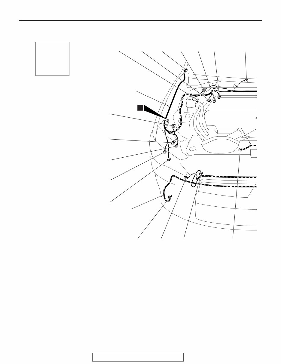
ENGINE COMPARTMENT <TURBO> TSB Revision CONFIGURATION DIAGRAMS 80A-10 ENGINE COMPARTMENT <TURBO> M1801000307445 ACA00199 A-48 A-01 A-02 A-51 A-44 A-43 A-42 A-41 A-47 A-61 A-46 A-50 A-45 1 AB A-04 A-62 A-63 Connector symbol A Front wiring harness Fog light wiring harness Front impact sensor wiring harness Connector color code B: Black BR: Brown G: Green GR: Gray L: Blue None: Milk white O: Orange R: Red V: Violet Y: Yellow A-01 (2-B) Side turn-signal light (RH) A-02 (2-B) Front wheel speed sensor (RH) A-04 (5-GR) Windshield wiper motor A-05 (4-GR) Mass airflow sensor A-06 (2-B) Brake fluid level switch A-07 (2-B) Front wheel speed sensor (LH) A-08 (2-B) Side turn-signal light (LH) A-11X (4) Fog light relay A-12X (4) Horn relay A-13X (4) A/C compressor clutch relay A-14X (4) No connection A-16X (4) No connection A-17X (4) Headlight relay (High) A-18X (4) Throttle actuator control motor relay A-20X (4) Daytime running light relay <Vehicles with discharge type headlight> A-21X (4) Injector relay A-22X (4) Electric pump relay A-24X (4) Starter relay A-25X (4) Headlight relay (Low) A-30X (4) MFI relay A-31 (12-B) Headlight assembly (LH) A-32 (6-B) Headlight assembly (LH) A-33 (4-B) Front wiring harness and front impact sensor wiring harness combination A-34 (2-B) Fog light (LH) A-35 (2-B) Radiator fan motor A-36 (2-B) Ambient temperature sensor A-37 (1-B) Horn (Low) A-38 (2-Y) Front impact sensor (LH) A-39 (2-B) Front wiring harness and fog light wiring harness combination
Get the complete service and repair manual for the 2011 Mitsubishi Lancer/Lancer Sportback. This detailed manual covers production model year 2011 and includes every single detail for all models and engines, making it an invaluable resource for both professional mechanics and DIY enthusiasts.
Engine overhaul and rebuilding
Brakes
Sunroof
Timing belt replacement
Trouble codes
Wiring diagrams
Troubleshooting and diagnostics
Computer diagnostic trouble tree charts
Engine performance
Front end and alignment procedures and specifications
Suspension
Transmission removal and installation
Air conditioning service and capacities
Transmission in-car servicing
Computer diagnostic codes
Firing orders
Detailed specifications on every model covered
Factory maintenance schedules and charts
Serpentine belt routings with diagrams
Brake servicing procedures
Driving concerns
Complete torque specifications
U-joint and CV-joint service procedures
Repair procedures
Complete wiring diagrams
Hundreds of illustrations
Vacuum diagrams
And more...
Model Specification: 2011 Mitsubishi Lancer/Lancer Sportback
Model Year: 2011
Language: English
Total Pages: more than 3000 pages
File Format: PDF
Requirements: Adobe Reader & Windows
Zoom in/out: Yes
Printable: Yes
Compatible: All Versions of Windows & Mac
This vehicle-specific manual is the exact same manual used by dealership technicians to maintain, service, diagnose, and repair your vehicle. It provides complete step-by-step instructions, diagrams, illustrations, wiring schematics, and specifications for easy vehicle repair.
All pages are printable, allowing you to print only the pages and diagrams you require. The manual is compatible with Windows 7, Vista 32 and 64, XP, ME, 98, NT, 2000, and Mac. Instant delivery upon receipt of payment.
Save money by doing your own repairs with these easy-to-follow, step-by-step instructions. Tons of pictures and diagrams are at your fingertips, making it easy for any skill level to use.
Recently Viewed
5,521,897Happy Clients
2,594,462eManuals
1,120,453Trusted Sellers
15Years in Business
Price:
Actual Price:
2011 Mitsubishi Lancer/Lancer Sportback Service & Repair Manual