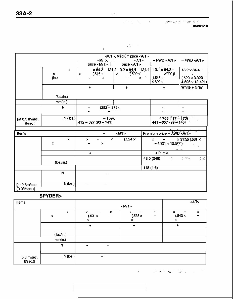
FRONT SUSPENSION - General Information GENERAL INFORMATION ’ ” ,I I. P @q),? .Isl _’ ;:” ‘^ ‘;&y $ ,,j’, ‘T’ 332ooo10135 The front suspension is of a multi-link construction by mounting the upper arm in a higher position with two lower arms which create the ideal virtual than the tires, excellent steering stability and ride kingpin axis for the suspension system. In addition, comfort are obtained. .” <ECLIPSE> ,.. - .i items Medium price CM/T>, Medium ppce <A/T>, High price <M/T>, I Premium price I Premium price High price <AK>, I - FlA’D <M/T> -FWD<A/T> 1 Low urice <M/T> i 1 Low urice <AK>. , 1. **, ‘ I Coil spring Wire diameter x O.D. x free length 13.1 x84.2-124.2 13.2x84$-124.4 .,;13.i,x84.2- x 309.5 (516 x x 315.5 (:520 X’ mm (in.) 3.315 - 4.890 x 3.323 - 4.898 x ” 124.2 x%69,5 t.51’6 x 3.315 - I 12.185) 1 12.421) 1 i.890 x 12.185) I Identification color 1 White + Pink 1 White + Grav I White + pink I 13.2x84.4- 124.4 x 315.5 Spring constant 43.0 (246) 43.0 (246) I 43.0 (246) N/mm (Ibs./in.) I 43.0 (246) I Shock absorber stroke mm(in.) 118 (4.6) j 118 (4.6) 116 (4.6) 1 118 (4.6) Shock Expansion N (Ibs.) 1255 - 1667 (282‘- 379) 1432 - 1902 (322 - 528) absorber 1167 - 1579 (267 - 355) 1481 - 1952 (333 - 439) damping force Iat 0.3 dsec. Contraction N (Ibs.) 471 -706 (106 - 159), 520 1755 (‘117: i7s) 4.41 ->657* (g& I&$) 1”” ,. (0.9 fthec.)] 412-627(93-141) ’ ? Items 1 Premium price - AWD <M/T> ,$, *p .j . , ” * ) premium price i A$VD”&/l$ ” 1 Coil spring Wire diameter x 13.3 x 84.6 - 124.6 x 312.0 (.524 x 13.5 x 85.0 - 125.0 x ‘3178‘(.531 * x O.D. x free length 3.331 - 4.906 x 12.283) 3.346 - 4.921 ., mm (in.) x 12.566) .I ,,/ ) /I. ,j”ll + Identification color Green ,+ Light blue Green + Pu$e Spring constant 43.0 (246) 43.0(246) ., ,-:“;+ ‘; :p; N/mm (Ibs./in.) Shock absorber stroke mm (in.) 118 (4.6) 1 llg(4.6) Shock Expansion N (Ibs.) 1432 -1902 (322 - 428) absorber damping force fat 0.3m/sec. Contraction N (Ibs.) 530 - 785 (119 - 176) <ECLIPSE SPYDER> TSB Revision 1 Items Medium price Premium price <M/T> Premium price <A/T> Coil spring Wire diameter x 13.5 x 85.0 - 125.0 x 13.6 x 85.2 - 125.2 x 13.8 x 85.6 - 125.6 x O.D. x free length 304.5 (.531 x 3.346 - 309.5 (.535 x 3.354 - 315.0 (.543 x 3.370 - mm (in.) 4.921 x 11.988) 4.929 x 12.165) 4.945 x 12.402) Identification color Cream + Purple Cream + Red Cream + Light blue Spring constant 43.0 (246) 43.0 (246) 43.0 (246) N/mm (Ibs./in.) Shock absorber stroke mm(in.) 118 (4.6) 118 (4.6) 118 (4.6) Shock Expansion N (Ibs.) 1206 - 1638 (271 - 368) absorber damping force [at 0.3 m/set. Contraction N (Ibs.) 471 -706 (106 - 159) (0.9 ftkec.)] / ;: ‘l. 4 y., ~ :2. ‘ , , -I
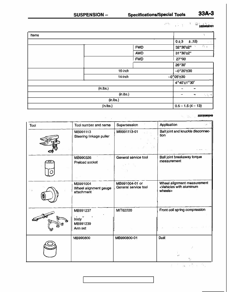
FRONT SUSPENSION: - Service SpecificatiodSpeciaf Tools 33K.3 SERVICE SPECIFICATIONS ,r.. : ,< ‘A’$ ,a ; ‘24 aa2’bo’iwbror Items 1 Standard value : Toe-in mm (in.) Steering angle Inner wheel - O.f3 (0 $..12) ,, .: IFWD 3203o’e’ -I /‘! : . : Camber I AWD 31”3o’f2” li Outer wheel IFWD 1 27”OO I 1 AWD FWD (Vehicles with 16-inch wheels) 26”30’ -0”2O’f30 FWD (Vehicles with 14-inch wheels), AWD -0”05’f30 4”40’f1630’ .- Caster Upper arm ball joint breakaway torque Nm (in.lbs.) 0.3 - 2.5 (3 - 22) Compression lower arm ball joint breakaway torque Nm (in.lbs.) 0.5 - 2.5 (4 7 22) .> -:: ‘.+ Lateral lower arm ball joint breakaway torque Nm (in.lbs.) Stabilizer link ball joint breakaway torque Nm (in.lbs.) 1.5 (13) or less 0.5-1.5(4-13) SPECIAL TOOLS Spring compressor MB990800 MD990600-01 Duif cover installation” 0 Q Ball joint remover and installer 9’ ‘a /’ “. .: TSB Revision
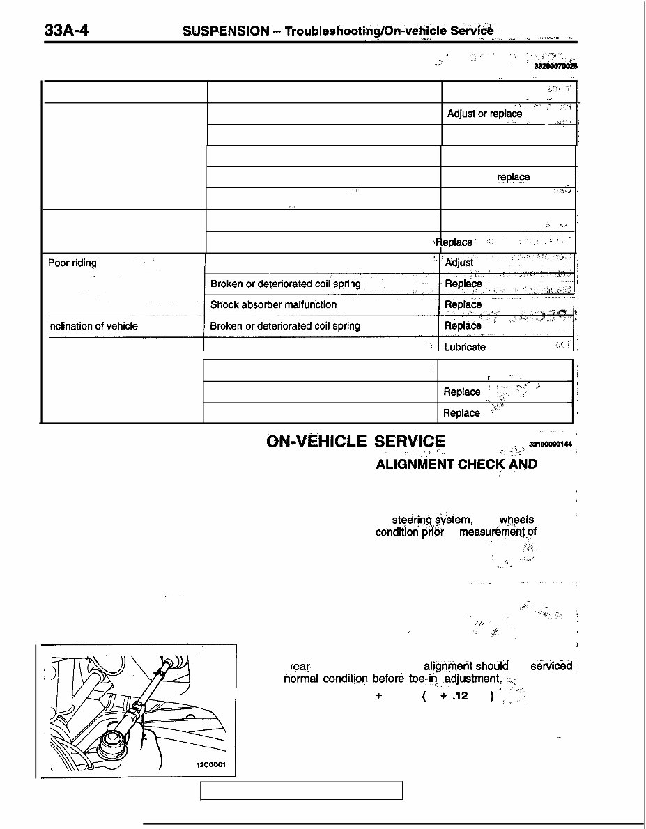
33A-4 FRONT S.USPENSION - Troubleshootirig/On&ehicld Set&& ’ *. _. ^,, .iy,,” __ ..~ ,.“, _r ,,,‘ _i/.z*w‘a 7 JI TROUBLESHOOTING ,,I: l’ ’ 7 ,. 6; , ‘^ ,, c .,,I . i ,, I ._ .^ -. Symptom Probable cause Remedy ,:,pi -,* ” _ ._. < i Steering wheel is heavy, vibrates Suspension malfunction ‘.” :-’ .c::j i or pulls to one side Adjust or replace’ ‘. , , .=,:I J i Ball joint Adjust or replace -. : Coil spring Wheel alignment Unbalanced or worn tires Adjust or replace Adjust or replace i i. ! I ’ Adjust or replace ““’ Excessive vehicle rolling .,, Broken or deteriorated stabilizer Shock absorber malfunction - Replace 1 :., ii’ ’ .___ $,ReDlam’ ‘ir ‘- ;^‘!.,* : i : L’ ? q Improper tire inflation pressure Noise Lack of lubrication Looseness and wear of each part . Broken coil spring Shock absorber malfunction .’ Replace _, ~_ r Replace ,,: ;--*, :‘;:‘r’ iJ P Replace :.Fi ! ON-VEHICLE SERViFFi, .-:r-‘ moot&h 1 FRONT WHEEL ALlGNtiktiT CHECK APfD ADJUSTMENT I Measure wheel alignment with alignment equipment on a I level surface. The ‘front’ ‘suspension, steering &tern, and yhgels should ’ be serviced to normal contlidoti pt?ok to measur6m&qf wheel alignment. id ,I : fp; ; .i % ,\ .-.ii,J 1.. c ;&‘. ._ ‘.. ,, ‘W:y’, ; ,i/” ., t / ‘L $#‘/ ‘, , TOE-IN i The rear. suspension wheel alignmerit shotild be s&k&d : to normal conditjo,? before toe-i? ,gdjustment! :“;, Standard value: 0 + 3 mm ( 0 f.. .12 in. ) ’ 1. 1,’ I”, .- TSB Revision
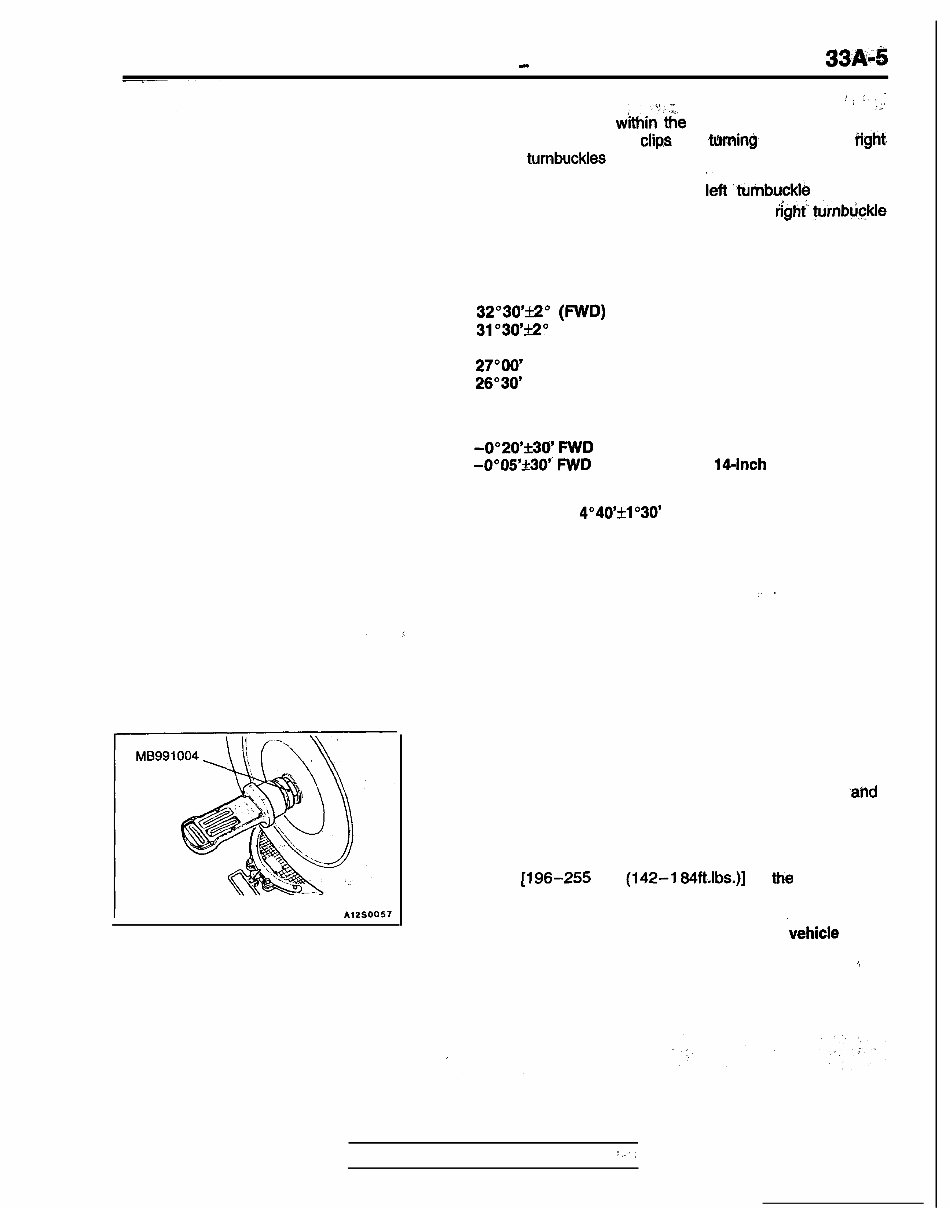
FRONT SUSPENSION - On-vehicle Service ,( ,Ij ” NOTE rl . :.‘, 1. If the toe-in is not withinthe standard value, adjust the toe-in by undoing, the c1ip.s and tWning~ the left arid tight, tie rod turnbuckles by the same amount (in opposite direc- tions). 2. The toe will move out as the teft turnbuckle is turned toward the front of the vehicle and the right’turnbuckle is turned toward the rear of the vehicle. STEERING ANGLE Standard value: Inner wheel 32”3O’ti” (FWD) 31”3O’f2” (AWD) Outer wheel 27”OO’ (FWD) 26”30’ (AWD) CAMBER Standard value: -O”20’f30’ FWD (Vehicles with lbinch wheels) -0”05’f30” FWD (Vehicles with 14inch wheels), AWD CASTER Standard value: 4”40’fl”30’ I ” NOTE 1. Camber and caster are preset at the’factory and cannot be adjusted. 2. If camber is not within the standard value, check .ahd replace bent or damaged parts. 3. For vehicles with aluminum type’ wheels, attach the camber/caster/kingpin gauge to the drive shaft by ‘using the special tool. Tighten the special tool, to the same torque [196-255 Nm (142-l 84Rlbs.)] as ttie drive shaft nut. Caution Never subject the wheel bearings to the .vehicle load when the drive shaft nuts are loosened. ,~ TSB Revision i:,
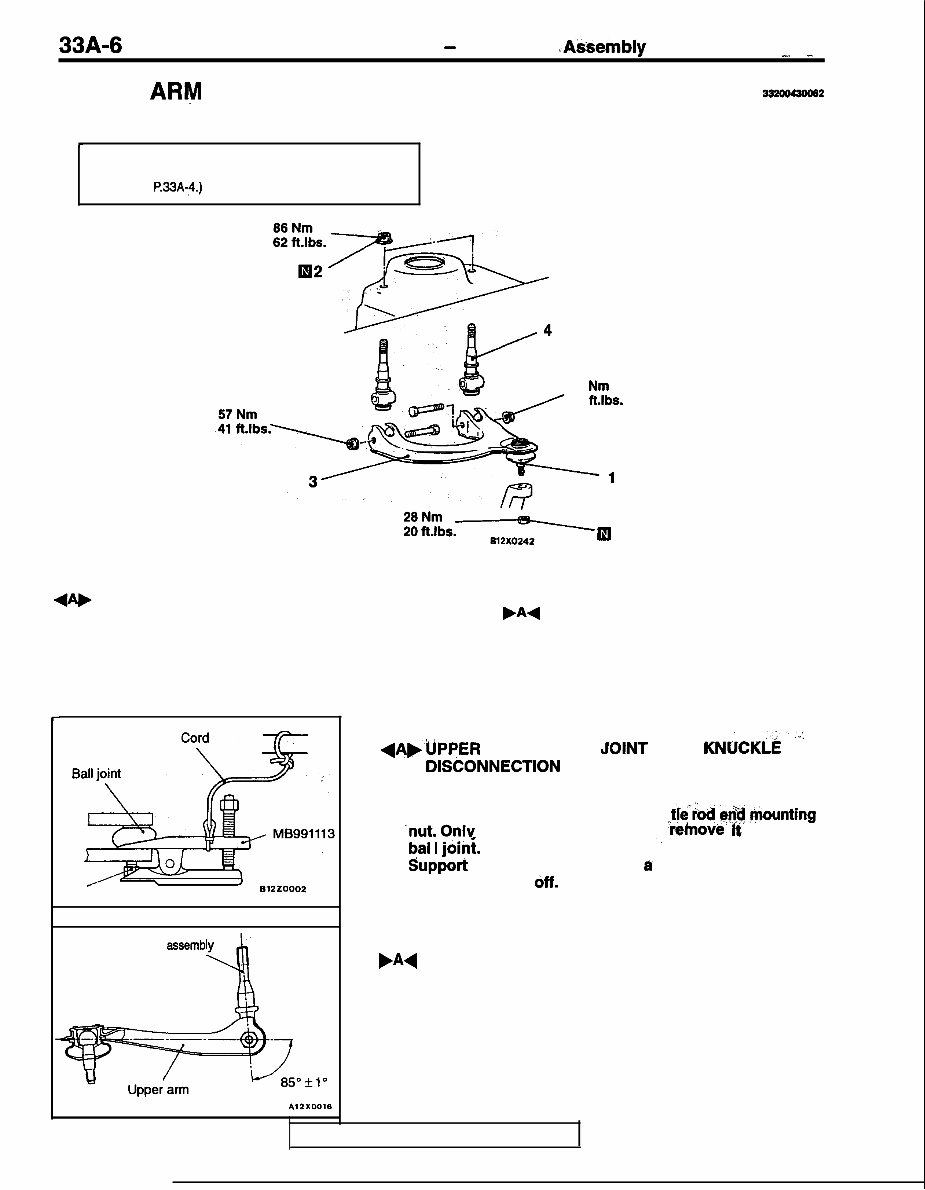
33A-6 FRONT SUSPENSION - Upper Arm .hsembly . -,, -, UPPER ARM ASSEMBLY REMOVAL AND INSTALLATION I- Post-installation Operation Front Wheel Alignment Adjustment (Refer to P.33A-5) 57 Nm 41 ft.lbs. Bl2XO242 Removal steps 1. Upper arm ball joint and knuckle connection 2. Upper arm self-locking nut 3. Upper arm assembly .A4 4. Upper arm shaft assembly c Nut Upper arm shaft assemblv d 332oo430062 REMOVAL SERVICE ‘POINT dAbUPPER ARM BALL JOtNT AND KNUCKLi ’ :” DlSCONNECTlON Caution 1. Use the special tool to loosen the tie’iod &$i ,hounting -nut. Onlv loosen the nut: do not ‘k)nov& it from the bal I joini. ‘, 2. support the special tool with I cord; etc. to prevent it from coming 6ff. INSTALLATION SERVICE POINT ,A4 UPPER ARM SHAFT ASSEMBLY INSTALLATION Install the upper arm shaft assembly at the angle shown in the illustration. NOTE If the upper arm shaft is installed at the above-mentioned angle, the reference dimension is determined as follows; TSB Revision
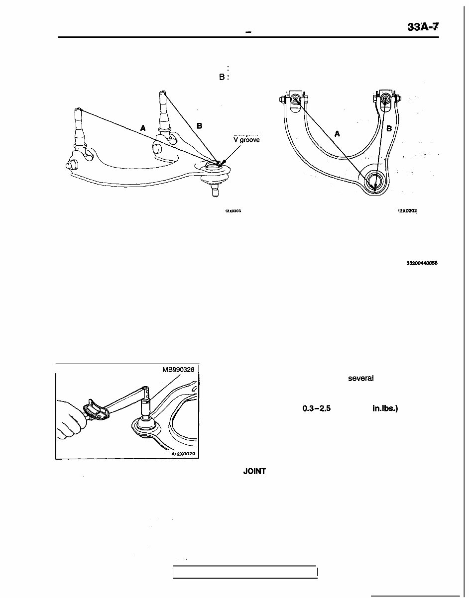
FRONT SUSPENSION - Upper Arm Assembly 33~93 A : 299.9 mm (11.8 in.) B : 234.0 mm (9.2 in.) ., Ball joint case 121(0203 12X020? 00000009 INSPECTION 332om4oo58 l Check the bushings for wear and deterioration. l Check the upper arm for bends or damage. l Check all bolts for condition and straightness. I MB990326 1 A12X0020 BALL JOINT BREAKAWAY TORQUE CHECK (1) After shaking the ball joint stud several times, install the nut to the stud and use the special tool to measure the breakaway torque of the ball joint. Standard value: 0.3-2.5 Nm (3-22 in.lbs.) (2) When the measured value exceeds the standard value, replace the upper arm assembly. (3) When the measured value is lower than the standard value, check that the ball joint turns smoothly without excessive play. If so, it is possible to use that ball joint. BALL JOINT DUST COVER CHECK If there are any cracks in or damage to the dust cover, replace the arm assembly. 1 TSB Revision
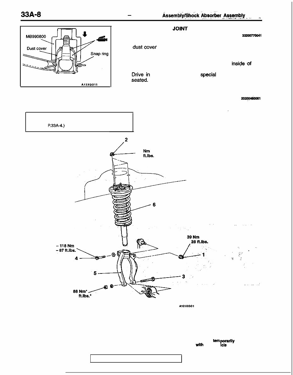
33A-8 FRONT SUSPENSION - Upper Arm Assembl@hock $bs&$er~,~~~~~~!y ,_ _,I . , I A12XOOlS UPPER ARM BALL JOINT DUST COVER REPLACEMENT 33200770041 Replace the dust cover by the following procedure only if the d&t covel has become damaged by accident during servicing. (1) Remove the dust cover. (2) Apply multipurpose grease to the lip and inside, .of the dust cover. (3) F;Fe;n the dust cover with special tool until it is fully . SHOCK ABSORBER ASSEMBLY 332C!MkW31 REMOVAL AND INSTALLATION - I , Post-installation Operation Front Wheel Alignment Adjustment (Refer to P.33A-4.) 88 -118Nm 65 -87ft.lbs;\/Q- 44 Nm L- 32 ft.lbs. ‘-3 39Nm .28 ft.lbs. / 88Nm’/ @’ 65 R.lbs.* ,‘. ., ‘ * < ‘$..J :I .ti _’ ; I. . Al2lOOOl Removal steps 1. Stabilizer link mounting nut 2. Shock absorber upper mounting nuts 5. Damper fork 6. Shock absorber assembly 3. Shock absorber lower mounting bolt 4. Damper fork mounting bolt Caution l : Indicates parts which should be tern orarlly tightened, P and then fully tightened wlth the veh cle on the ground in the unladen condition. TSB Revision
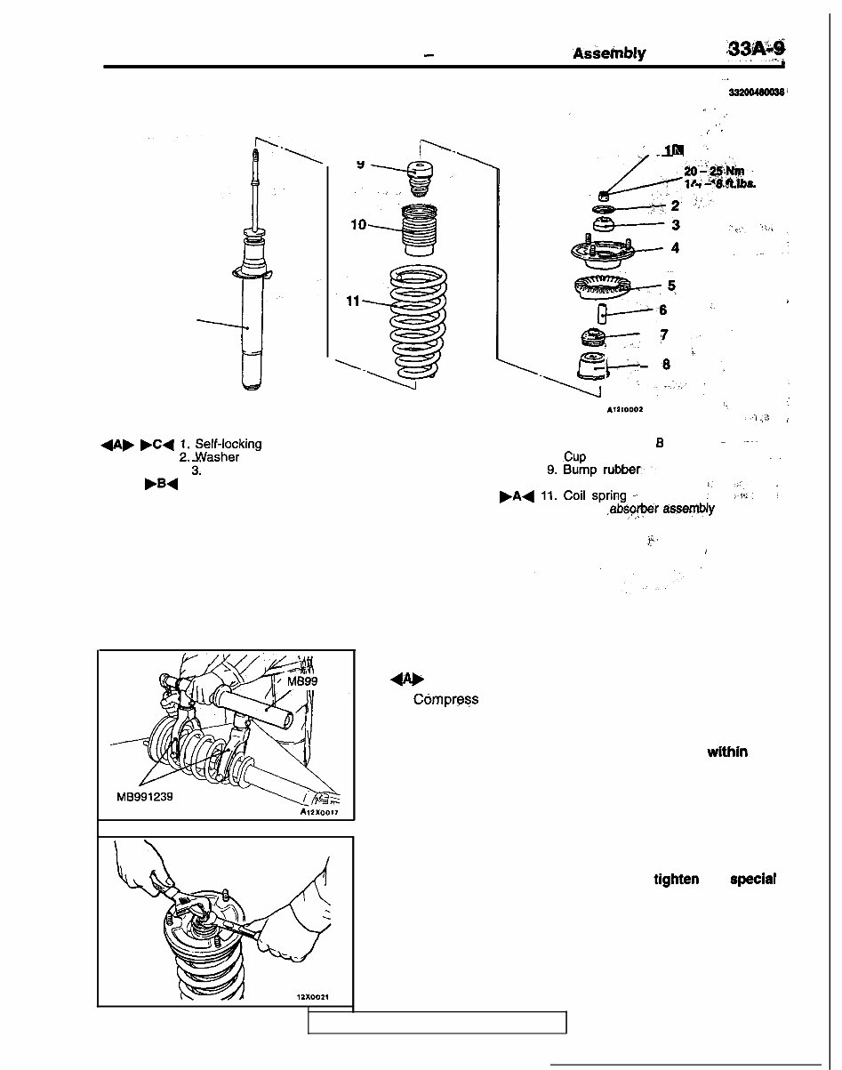
FRONT SUSPENSION - Shock Absorber ‘Askehbly &y&g c ..- DISASSEMBLY AND, REASSEMBLY 332mmaw 12 ” ” , _’ ,’ : r _ 9 .y-\ .I.39 ‘;’ 1m ‘* ,, ._k- ,, :,o$fi&~ 1, ‘2. );!Y. ” ’ * -3 ” ,..t_ ‘!T,‘l ,, -4 ..- - - :_ t ,-, &T ‘, i.’ ‘I” y Disassembly steps di+ .C( :. Sel~a;king nut 3: Upper bushing A bB4 4. Upper bracket assembly 5. Upper spring pad 6. Collar 1237 ; . MB991239 AllI ‘., : : iY, .;A / 7. Upper bushing B ._ ,-.. 8. .Cup assembly g.Bumprubber:,- . . _. 10. Dust cover .A+ 11. Coil spring .‘. r’ j’!k. s; 12. Shock ,abs~qr$er as.se+ly ii,, ” , i DISASSEMBLY SERVICE POINT 4A, SELF-LOCKING NUT REMOVAL (1) Ccimpress the coil spring using the special tools. Caution 1. Install the special tools evenly so that the maximum length will be attained within the installation range. 2. Do not use an impact wrench to tighten the special tool bolt. (2) While holding the piston rod, remove the self-locking nut. Caution Do not use an impact wrench to tlghten the special tool bolt. TSB Revision
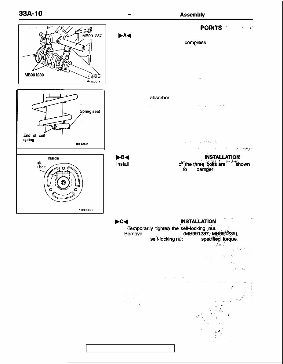
33A-10 FRONT SUSPENSION - Shock Absorber Assembly AlZX0017 Damper fo installation Inside of the body AlZXOOOB REASSEMBLY. SERVICE POI-IVTS i >” 1 .+’ ,A+ COIL SPRING INSTALLATION (1) Use the special tools to comgfess the coil spring and install it to the shock absorber. Caution Do not use an impact wrench to tighten the bolt of the special tool. (2) Align the edge of the coil spring to the stepped part of the shock absorber spring seat. I ,1 T *; 1 .@;“,<*.. ,.;,,. .B+ UPPER BRACKET ASSEMBLY fN@iL~~;fN Install so that the position ofthe three,&%& ire as’ Shown in the illustration with respect ‘t’o the darn&?, fork installation bolt. . .C+ SELF-LOCKING NUT ,lNSTAiLATiOw _ .- . . - (1) ,Temporayily tighten the @lo&king ,n;t. ‘ + (2). IjIemove the special tools (MB99j237; M&&$39), and tighten the self-lodking nbt to- the spe&i6$.?qr&e. , I ,>’ I.. I, Caution j.‘/-, Do not use an impact wrench. :, ‘, “‘- ~ ;: - ., ‘: ,): :. ., I. ..( / ‘I ?“) : .*i. .,__ / i t ’ v.- “‘j i : ( ^ >.i;; ” ,: ’ .f“ ‘,+) f. ‘. .:‘, %. s , .:, ’ ‘_ .,.:+ ’ ,~ , :’ .” .-. - TSB Revision
1992-1996 Mitsubishi Lancer Evo 1, Evo 2, Evo 3 Service & Repair Manual
Models covered:
Lancer Evolution I (CD9A)
Lancer Evolution II (CE9A)
Lancer Evolution III (CE9A)
Engine covered:
2.0L 4G63T I4 Turbocharged
This 1992-1996 Mitsubishi Lancer Evolution I, II, III (Evo 1, Evo 2, Evo 3) Service & Repair Manual covers the CD9A and CE9A chassis with the 2.0L 4G63T turbocharged inline-four. Whether you're maintaining a street-driven Evo or refreshing a track build, this manual lays out the factory procedures used by the pros.
It includes step-by-step service instructions for engine disassembly, turbo system checks, transmission and clutch work, suspension setup, cooling system maintenance, and drivetrain inspections. You'll also get factory torque specs, tolerances, and scheduled maintenance guidelines—everything you need to keep the car running right.
This is a technical guide built for people doing the work. If you're turning wrenches on one of these early Evos, this manual gives you the reference info to do it properly, without having to rely on secondhand advice or forum guesswork.
Printable: Yes Language: English Compatibility: Pretty much any electronic device, incl. PC & Mac computers, Android and Apple smartphones & tablet, etc. Requirements: Adobe Reader (free)
Recently Viewed
5,521,897Happy Clients
2,594,462eManuals
1,120,453Trusted Sellers
15Years in Business
Price:
Actual Price:
1992-1996 Mitsubishi Lancer Evolution I, II, III Service & Repair Manual

 Workshop Repair Service Manual")