
 Service & Repair Manual 1991-1999")
Mitsubishi GTO (3000GT) Service & Repair Manual 1991-1999
What's Included?
Fast Download Speeds
Offline Viewing
Access Contents & Bookmarks
Full Search Facility
Print one or all pages of your manual
Volume lm
I ‘k
,‘6
I
I
I
Engine, Chassis & Body
f
d
L’ BackupServiceManual
3OOOG-r
1991: Volume 1
FOREWORD
L
This Service Manual has been prepared with the
latest service information available at the time of
publication. It is subdivided into various group
categories and each section contains diagnosis,
disassembly, repair, and installation procedures
along with complete specifications and tightening
references. Use of this manual will aid in properly
performing any servicing necessary to maintain or
restore the high levels of performance and reliability
designed into these outstanding vehicles.
/
WE SUPPORT
VOLUNTARY TECHNICIAN
CERTIFICATION THROUGH
I/
National ,nwtute ‘or II
AUTOMOTIVE
SERVICE
EXCELLSNCE
/I
MITSUBISHI
MOTOR SALES OF AMERICA. Inc.
Mitsubishi Motors Corporation reserves the right to make changes in
design or to make addltlons to or tmprovements in Its products without
Imposing any obligations upon Itself to install them on its products
previously manufactured.
li
@ 1990 Mitsubishi Motors Corporation Rqwinted in USA
GROUP INDEX MOOAA- -A
I
General
.............................................
Engine
..............................................
Fuel
. . . . . . . . . . . . . . . . . . . . . . . . . . . . . . . . . . . . . . . . . . . . . . . . . . .
Cooling
.............................................
Intake and Exhaust
..........................
Emission Control
.............................
Clutch
................................................
Manual Transaxle
............................
Automatic Transaxle .......................
Propeller Shaft
.................................
Front Axle
.........................................
Rear Axle
..........................................
Wheel and Tire
.................................
Power Plant Mount
..........................
Front Suspension
............................
Electronic Control Suspension .......
Rear Suspension
..............................
Service Brakes
.................................
Parking Brakes
.................................
Steering
............................................
4-Wheel Steering System (4WS) -
Body
. . . . . . . . . . . . . . . . . ..*.............................
Exterior
. . . . . . . . . . . . . . . . . ..*..........**.............
Interior
..*............*......*.......................
Su;$emental Restraint System ....
Heater, Air Conditioner
and Ventilation
*......*...........
I
NOTE:
For Electrical, refer to Volume-2 “Electrical”
I
I
I I
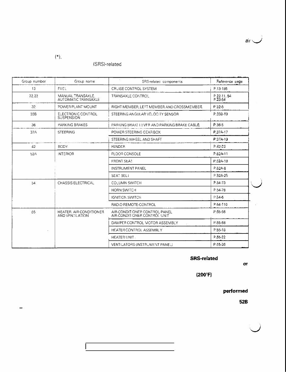
SUPPLEMENTAL RESTRAINT SYSTEM (SRS)
(1) A Supplemental Restraint System (SRS), which uses a driver-side air bag, has been installed in the
3000GT.
(2) The SRS includes the following components: impact sensors, SRS diagnosis unit; SRS warning light, dir J
bag module, clock spring, interconnecting wiring. Other SRS-related components (that may have to be
removed/installed in connection with SRS service or maintenance) are indicated in the table of contents
by an asterisk (*).
The Supplemental Restraint System (SRSI-related components are shown in the following MASTER TABLE
OF CONTENTS. Be sure to carefully read and understand the WARNING below before proceeding.
Group number
22.23
32
36
42
52A
Group name SRS-related components
FUEL CRUISE CONTROL SYSTEM / P.13-185
MANUALTRANSAXLE. TRANSAXLE CONTROL
AUTOMATIC TRANSAXLE
POWER PLANT MOUNT RIGHT MEMBER, LEFT MEMBER AND CROSSMEMBER P.32-6
ELECTRONIC CONTROL
SUSPENSION
’ STEERING ANGULAR VELOCITY SENSOR P.33B-19
PARKING BRAKES PARKING BRAKE LEVER AND PARKiNG BRAKE CABLE / P.36~5
I
STEERING / POWER STEERING GEAR BOX / P.37A-17
/ STEERING WHEEL AND SHAFT j P.37A-13
BODY
INTERIOR
FENDER
FLOOR CONSOLE / P.52A-11
FRONT SEAT
INSTRUMENT PANEL
P52A-18
P.52A-8
CHASSIS ELECTRICAL
SEAT BELT
COLUMN SWITCH
HORN SWITCH
IGNITION SWITCH
P.52A-25
P.54-73
P.54-78
1 P.54-6
RADIO REMOTE-CONTROL / P.54.110
HEATER, AIR CONDITIONER AIR-CONDITIONER CONTROL PANEL
AND VENTILATION AIR-CONDITIONER CONTROL UNIT
P.55-56
/ DAMPER CONTROL MOTOR ASSEMBLY
I
/ HEATER CONTROL ASSEMBLY 1 P.55-18
I
HEATER UNIT. 1 P.55-22
WARNING!
VENTILATORS (INSTRUMENT PANEL) P.55-36
(1) Improper service or maintenance of any component of the SRS, or any SRSrelated component,
can lead to personal injury or death to service personnel (from inadvertent firing of the air bag) or
to the driver (from rendering the SRS inoperative).
(2) If it is possible that the SRS components are subjected to heat over 93°C (260°F) in baking or in
drying after painting, remove the SRS components (air bag module, SRS diagnosis unit, front
impact sensors) beforehand.
(3) Service or maintenance of any SRS component or SRS-related component must be perfarmed
only at an authorized MITSUBISHI dealer.
(4) MITSUBISHI dealer personnel must thoroughly review this manual, and especially its GROUP 52B
- Supplemental Restraint System (SRS), before beginning any service or maintenance of any
component of the SRS or any SRS-related component.
1 TSB Revision
I
,
b
00-I
GENERAL
CONTENTS MOOOA- .
GENERAL DATA AND SPECIFICATIONS . . . . . . 21
HOW TO USE THIS MANUAL . . . . . . . . . . . . . . . . . . . . . . . . . . . . 3
Definition of Terms . . . . . . . . . . . . . . . . . . . . . . . . . . . . . . . . . . . . . . . . . . . . 3
Explanation of Circuit Diagrams . . . . . .._........... 7
Explanation of Manual Contents . . . . . . . . . . . . . . . . . . . . 4
Explanation of the Troubleshooting Guide . . 6
Model Indications . . . . . . . . . . . . . . . . . . . . . . . . . . . . . . . . . . . . . . . . . . . . 3
Scope of Maintenance, Repair and
Servicing Explanations . . . . . . . . . . . . . . . . . . . . . . . . . . . . . . . . . . . . 3
Troubleshooting . . . . . . .._....................................... 3
LUBRICATION AND MAINTENANCE . . . . . .._.... 31 SCHEDULED MAINTENANCE TABLE . . . . . . .._.
MAIN SEALANT AND ADHESIVE TABLE . . . 44
MAINTENANCE SERVICE . . . . . . . . . . . . . . . .._......_.....__
Air Cleaner Element . . . . . . .._......._......_................
Automatic Transaxle . . . . . . . . . . . . . . . . . . . . . . . . .._......._.....
Ball Joint and Steering Linkage Seals . . . . . . . . . . . .
Brake Hoses . . . . . . . . . . . . . . . . . . . . . . . . . . . .._......._.._...._......._..
Disc Brake Pads . . . . . . . . . . . . . . . . . . . . . . . . . . . . . . . . . . . . . . . . . . . . . . . .
Drive Belt (For Alternator) . . . . . . . . .._.........._..........
Drive Shaft Boots . . . . . . . . . . . . . . . . . . . . . . . . . . . . . . . . . . . .
Engine Coolant . . . . . . . . . . . . ..__.._.............................
Engine Oil .._....__._.................................................
Engine Oil Filter . . . . .._._.......__.................. . . . . . . . . . . .
Exhaust System _....._......._.....__._............,...........
Fuel Hoses ..__......__............................................
36
37
40
42
42
42
38
43
41
38
39
43
36
Fuel System . . . . . . . . . . . . . . . . . . . . . . . . . . . . . . . . . . . . . . . . . . . . . . . . . . . . . . . .
Manual Transaxle . . . . . . . . . .._........................_.......
Rear Axle . . . . . . . . . . . . . . . . . . . . . . . . . . . . . . . . . . .._..._.._..____.._.......
Spark Plugs . . . . . . . . . . . . . . . . . . . . . . . . . . . . . . . . . . . . . . .._...............
Timing Belt . . . . . . . . . . . . . . . . . . . . . . . . . . . . . . . . . . . . . . . . . . . . . . . . . . . . . . . .
MASTER TROUBLESHOOTING . . . . . . . . . . . . . . . . . . . . . . . .
PRECAUTIONS BEFORE SERVICE . . . . . . . . . . . . . . . .
RECOMMENDED LUBRICANTS AND
LUBRICANT CAPACITIES TABLE . . . . . . .._........
SPECIAL HANDLING INSTRUCTIONS
FOR AWD MODELS . . . . . . . . . . . . .._...._........................
TIGHTENING TORQUE . . . . . . . . . . . . . . . ..__.....................
TOWING AND HOISTING . . . . . . . . . . . . . . . . . . . . . . . . . . . . . . . .
VEHICLE IDENTIFICATION . . . . . . . . . . . . . . . . . . . . . . . . .._.....
Chassis Number . .._............................................
Engine Model Stamping .._..........................._...._
Theft Protection . . . . .._.........................................
Vehicle Identification Code Chart Plate .._.....
Vehicle Identification Number List .._._....._..._.
Vehicle Identification Number Location . . . .._
Vehicle Information Code Plate . . . . .._._......_.......
Vehicle Safety Certification Label . . . ..I . . . . .._..._...
36
39
43
37
37
24
15
32
35
20
23
16
8
10
11
11
8
9
8
10
10
GENERAL - How to Use This Manual 00-3
HOW TO USE THIS MANUAL MOOBAAF
c;
SCOPE OF MAINTENANCE, REPAIR AND DEFINITION OF TERMS
SERVICING EXPLANATIONS
STANDARD VALUE
b
This manual provides explanations, etc. concerning
procedures for the inspection, maintenance, repair
and servicing of the subject model. Unless other-
wise specified, each service procedure covers all
models. Procedures covering specific models are
identified by the model codes, or similar designation
(engine type, transaxle type, etc.). A description of
these designations is covered in this unit under
“VEHICLE IDENTIFICATION”.
SERVICE ADJUSTMENT PROCEDURES
“Service Adjustment Procedures” are procedures
for performing inspections and adjustments of
particularly important locations with regard to the
construction and for maintenance and servicing, but
other inspections (for looseness, play, cracking,
damage, etc.) must also be performed.
SERVICE PROCEDURES
The service steps are arranged in numerical order
and attentions to be paid in performing vehicle
service are described in detail in SERVICE POINTS.
TROUBLESHOOTING
Troubleshootings are classified into master trouble-
shooting and group troubleshooting and located as
follows:
The master troubleshooting is prepared when the
trouble symptom relates to two or more groups and
given in MASTER TROUBLESHOOTING.
The group troubleshooting guide is prepared for
causes of problems related to that individual group
Indicates the value used as the standard for judging
the quality of a part or assembly on inspection or the
value to which the part or assembly is corrected and
adjusted. It is given by tolerance.
LIMIT
Shows the standard for judging the quality of a part
or assembly on inspection and means the maximum
or minimum value within which the part or assembly
must be kept functionally or in strength. It is a value
established outside the range of standard value.
REFERENCE VALUE
Indicates the adjustment value prior to starting the
work (presented in order to facilitate assembly and
adjustment procedures, and so they can be com-
pleted in a shorter time).
CAUTION
Indicates the presentation of information particularly
vital to the worker during the performance of
maintenance’ and servicing procedures in order to
avoid the possibility of injury to the worker; or
damage to component .parts, or a reduction of
component or vehicle function or performance, etc.
INDICATION OF TIGHTENING TORQUE
The tightening torque shown in this manual is a
basic value with a tolerance of +lO% except the
following cases when the upper and lower limits of
tightening torque are given.
(1) The tolerance for the basic value is within
+ I no/-
only; a troubleshooting guide is prepared for each
I iv,“.
appropriate group.
(2) Special bolts or the like are in use.
(3) Special tightening methods are used.
MODEL INDICATIONS
The following abbreviations are used in this manual for classification of model types.
M/T: Indicates the manual transaxle, or models equipped with the manual transaxle.
A/T: Indicates the automatic transaxle, or models equipped with the automatic transaxle.
MPI: Indicates the multi-point injection, or engines equipped with the multi-point injection.
Turbo: Indicates an engine with turbocharger, or a model equipped with such an engine.
Non-Turbo: Indicates an engine without turbocharger, or a model equipped with such an engine.
FWD: Indicates the front wheel drive vehicles.
AWD; Indicates the all wheel drive vehicles.
ABS: Indicates the anti-lock braking system or models equipped with the anti-lock braking system.
ECS: Indicates the electronic control suspension or models equipped with the electronic control
suspension.
4WS: Indicates the 4-wheel steering system or models .equipped with the 4-wheel steering system.
TSB Revision
You're Reading a Preview
What's Included?
Fast Download Speeds
Offline Viewing
Access Contents & Bookmarks
Full Search Facility
Print one or all pages of your manual
$41.99
Viewed 20 Times Today


Secure transaction
What's Included?
Fast Download Speeds
Offline Viewing
Access Contents & Bookmarks
Full Search Facility
Print one or all pages of your manual
$41.99
- Complete service and repair manual for the Mitsubishi GTO (3000GT) covering production years 1991-1999, with all styles included.
- Quality manual with over 3,100 pages in .PDF format, compatible with Windows, Mac, and Linux, and printable without any restrictions.
- Includes detailed illustrations, step-by-step instructions, and troubleshooting information for the vehicle's electrical system.
- Useful for both professional mechanics and DIY enthusiasts, providing comprehensive repair and service information.
- Each manual offers numbered instructions, cautions, warnings, and a detailed table of contents for easy navigation.
- Enlarged insets, photos, and diagrams aid in part identification and examination, making the repair procedures clear and manageable.
- Topics covered include engine, control systems, mechanical components, cooling and heating systems, brakes, suspension, steering, and more.
- Whether you're a seasoned mechanic or a do-it-yourselfer, this manual is an invaluable resource for maintaining and repairing your vehicle.
Direct Preview Link: Mitsubishi GTO (3000GT) Manual 1991-1999 Preview


