d LJ BackupService Manual 3OOOGl- 1992-l 996 Volume 1 FOREWORD This Service Manual has been prepared with the latest service information available at the time of publication. It is subdivided into various group categories and each section contains diagnosis, disassembly, repair, and installation procedures along with complete specifications and tightening references. Use of this manual will aid in properly performing any servicing necessary to maintain or restore the high levels of performance and reliability designed into these outstanding vehicles. 4iB A . I WE SUPPORT VOLUNTARY TECHNICIAN CERTIFICATION THROUGH Nat,Onal inmtute for AUTOMOTIVE SERVICE EXCELLENCE MITSUBISHI MOTOR SALES OF AMERICA Inc Mitsubishi Motors Corporation reserves the right to make changes in design or to make additions to or improvements in its products without imposing any obligations upon itself to install them on its products previously manufactured. c 0 1995 Mitsubishi Motors Corporation Reprintdin USA GROUP INDEX General ......................... Engine ......................... Fuel ........................... Engine Cooling ................. Intake and Exhaust ............ Engine and Emission Control ... Clutch ......................... Manual Transaxle .............. Automatic Transaxle ........... Propeller Shaft ................. Front Axle ..................... Rear Axle ...................... Wheel and Tire ................. Power Plant Mount ............. Front Suspension .............. Rear Suspension .............. Service Brakes ................ Parking Brakes ................ Steering ....................... Body .......................... Exterior ....................... Interior and Supplemental Restraint System (SRS) ........ Heater, Air Conditioning and Ventilation .. :. ................ Alphabetical Index ............. NOTE: Electrial system information is contained in Volume 2 “Electrical” of this paired Service Manual. For overhaul procedures of engines or transmis- sions, refer to the separately issued Engine Service Manual or Manual/Automatic Transmission Service Manual.
WARNINGS REGARDING SERVICING OF SUPPLEMENTAL RESTRAINT SYSTEM (SRS) EQUIPPED VEHICLES WARNING! (1) Improper service or maintenance of any component of the SRS, or any SRS-related component, can lead to personal injury or death to service personnel (from inadvertent firing of the air bag) or to the driver (from rendering the SRS inoperative). (2) If it is possible that the SRS components are subjected to heat over 93°C (200°F) in baking or in drying after painting, remove the SRS components (air bag module, SRS diagnosis unit, front impact sensors) beforehand. (3) Service or maintenance of any SRS component or SRS-related component must’be performed only at an authorized MITSUBISHI dealer. (4) MITSUBISHI dealer personnel must thoroughly review this manual, and especially its GROUP 52B - Supplemental Restraint System (SRS) and GROUP 00 - Maintenance Service, before beginning any service or maintenance of any component of the SRS or any SRS-related compo- nent. NOTE ,I Section titles with asterisks (*) in the table of contents in each group indicate operations requiring warnings. TSB Revision
GENERAL CONTENTS GENERAL DATA AND SPECIFICATIONS ... 26 HOW TO USE THIS MANUAL .............. 2 Definition of Terms ........................... 2 Explanation of Circuit Diagrams ............... 3 Explanation of Manual Contents ............... 4 Explanation of the Troubleshooting Guide ...... 6 Maintenance, Repair and Servicing Explanations ................................. 2 Model Indications ............................ 2 Special Tool Note ............................ 2 Troubleshooting .............................. 2 HOW TO USE TROUBLESHOOTING/ INSPECTION SERVICE POINTS ............. 7 LUBRICATION AND MAINTENANCE ....... 36 MAIN SEALANT AND ADHESIVE TABLE .. .61 MAINTENANCE SERVICE .................. 45 Air Cleaner Element ........................ 45 Automatic Transmission Fluid ................ 49 Ball Joint and Steering Linkage Seals ........ 52 Brake Hoses ............................... 52 Disc Brake Pads ............................ 52 Drive Belt (For Generator, Water Pump, Power Steering Pump) ............................. 47 Drive Shaft Boots ........................... 52 Engine Coolant ............................. 51 Engine Oil .................................. 47 Engine Oil Filter ............................ 48 Evaporative Emission Control System ......... 46 Exhaust System ............................ 60 / Fuel Hoses ................................. 45 Fuel System (Tank, Pipe Line, Connections and Fuel Tank Filler Tube Cap) .............. 45 Ignition Cables .............................. 46 Manual Transmission Oil .................... 48 Rear Axle Oil ............................... 52 Spark Plugs ................................ 46 SRS Maintenance ........................... 53 Timing Belt ................................. 46 Transfer Oil ................................ 51 MASTER TROUBLESHOOTING ............ 29 PRECAUTIONS BEFORE SERVICE ........ 18 RECOMMENDED LUBRICANTS AND LUBRICANT CAPACITIES TABLE .......... 38 SCHEDULED MAINTENANCE TABLE ..... .41 SPECIAL HANDLING INSTRUCTIONS FOR AWD MODELS ....................... 25 TIGHTENING TORQUE ................. a .. 28 TOWING AND HOISTING .................. 21 VEHICLE IDENTIFICATION ................. 11 Chassis Number ............................ 14 Engine Model Stamping ..................... 14 Theft Protection ............................. 15 Vehicle Identification Code Chart Plate ........ 11 Vehicle Identification Number List ............ 12 Vehicle Identification Number Location ......... 11 Vehicle Information Code Plate ............... 13 Vehicle Safety Certification Label ............. 14
00-2 GENERAL - How to Use This Manual HOW TO USE MAINTENANCE, REPAIR AND SERVICING EXPLANATIONS This manual provides explanations, etc. concerning procedures for the inspection, maintenance, repair and servicing of the subject model. Unless other- wise specified, each service procedure covers all models. Procedures covering specific models are identified by the model codes, or similar designation (engine type, transaxle type, etc.). A description of these designations is covered in this manual under “VEHICLE IDENTIFICATION”. SERVICE ADJUSTMENT PROCEDURES “Service Adjustment Procedures” are procedures for performing inspections and adjustments of par- ticularly important locations with regard to the construction and for maintenance and servicing, but other inspections (for looseness, play, cracking, damage, etc.) must also be performed. SERVICE PROCEDURES The service steps are arranged in numerical order and attention must be paid in performing vehicle service are described in detail in SERVICE POINTS. TROUBLESHOOTING Troubleshootings are classified into master trouble- shooting and group troubleshooting and located as follows: The master troubleshooting is prepared when the trouble symptom relates to two or more groups and given in MASTER TROUBLESHOOTING. The group troubleshooting guide is prepared for ’ causes of problems related to that individual group only; a troubleshooting guide is prepared for each appropriate group. DEFINITION OF TERMS STANDARD VALUE Indicates the value used as the standard for judging the quality of a part or assembly on inspection THIS MANUAL or the value to which the part or assembly is cor- rected and adjusted. It is given by tolerance. LIMIT Shows the standard for judging the quality of a part or assembly on inspection and means the maxi- mum or minimum value within which the part or assembly must be kept functionally or in strength. It is a value established outside the range of stan- dard value. REFERENCE VALUE Indicates the adjustment value prior to starting the work (presented in order to facilitate assembly and adjustment procedures, and so they can be com- pleted in a shorter time). CAUTION Indicates the presentation of information particularly vital to the worker during the performance of mainte- nance and servicing procedures in order to avoid the possibility of injury to the worker; or damage to component parts, or a reduction of component or vehicle function or performance, etc. INDICATION OF TIGHTENING TORQUE The tightening torque shown in this manual is a basic value with a tolerance of +lO% except the following cases when the upper and lower limits of tightening torque are given. (1) The tolerance for the basic value is within +lO%. (2) Special bolts or the like are in use. (3) Special tightening methods are used. SPECIAL TOOL NOTE Only MMC special tool part numbers are called out in the repair sections of this manual. Please refer to the special tool cross reference chart, which is located in the service manual at the beginning of each group, for a cross reference from the MMC special tool number to the special tool number that is available in your market. MODEL INDICATIONS The following abbreviations are used in this manual for classification of model types. M/TI Indicates the manual transaxle, or models equipped with the manual transaxle. A/T: Indicates the automatic transaxle, or models equipped with the automatic transaxle. MFI: Indicates the multiport fuel injection, or engines equipped with the multiport fuel injection. Turbo: Indicates an engine with turbocharger, or a model equipped with such an engine. Non-Turbo: Indicates an engine without turbocharger, or a model equipped with such an engine. FWD: Indicates the front wheel drive vehicles. AWD: Indicates the all wheel drive vehicles. ABS: Indicates the anti-lock braking system or models equipped with the anti-lock braking system. ECS: Indicates the electronic control suspension or models equipped with the electronic control suspension. 4WS: Indicates the 4-wheel steering system or models equipped with the 4-wheel steering system. ( TSB Revision ‘LJ ~ \ !ij ~ vi;
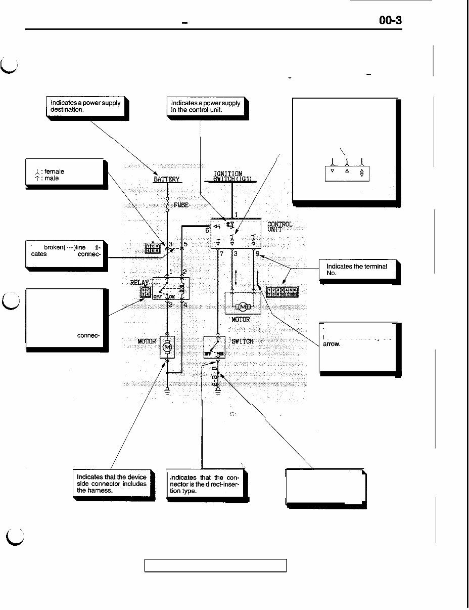
GENERAL - How to Use This Manual EXPLANATION OF CIRCUIT DIAGRAMS 00-3 I b The symbols used in circuit diagrams are used NOTE as described below. For detailed information concerning the reading of circuit diagrams, refer to Volume 2 - Circuit Diagrams. - The input/output (direction of cur- rent flow) relative to the electronic control unit is indicated by sym- bols. \ output r / input \ Input/output Indicates a connector. \ The broken( ----)line inc cates the same connec- tor. The connector symbol indicates the device side connector (for an intermediate connector, the male side connec- tor) as seen from the ter- minal front (the connec- I tor’s connection face). I i. Ita. \ ’ The direction of current flow is indicated by the In this instance, the cur- rent flow is in both direc- tions, up or down. Indicates the branch point of a harness of a different line diameter or line color. I \ c TSB Revision
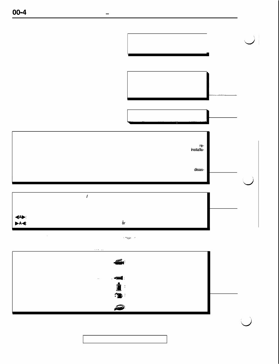
GENERAL - How to Use This Manual EXPLANATION OF MANUAL CONTENTS Indicates procedures to be performed before the work in that section is started, and proce- dures to be performed after the work in that section is finished. I - - - - - Component Diagram A diagram of the component parts is pro- vided near the front of each section in order to give the reader a better understanding of the installed condition of component parts. Indicates (by symbols) where lubrication is necessary. Maintenance and Servicing Procedures The numbers provided within the diagram indicate the l Installation steps: sequence for maintenance and servicing procedures. Specified in case installation is impossible in re- l Removal steps: verse order of removal steps. Omitted if installa- The part designation number corresponds to the tion is possible in reverse order of removal steps. number in the illustration to indicate removal l Reassembly steps: steps. Specified in case reassembly is impossible in l Disassembly steps: reverse order of disassembly steps. Omitted if The part designation number corresponds to the reassembly is possible in reverse order of disas- number in the illustration to indicate disassembly sembly steps. steps. Classifications of Major Maintenance I Service Points When there are major points relative to maintenance and servicing procedures (such as essential maintenance and service points, maintenance and service standard values, information regarding the use of special tools, etc.), these are arranged together as major maintenance and service points and explained in detail. +A,: Indicates that there are essential points for removal or disassembly. .A+: Indicates that there are essential points for installation 8r reassembly. . . _. __ Symbols for Lubrication, Sealants and Adhesives Information concerning the locations for lubrication and a: Grease for application of sealants and adhesives is provided, by (multipurpose grease unless there is a using symbols, in the diagram of component parts or on brand or type specified) the page following the component parts page, and ex- plained. ~_ .; 4 : Sealant or adhesive : Brake fluid or automatic transmission fluid * : Engine oil, gear oil or air conditioning compressor oil : Adhesive tape or butyl rubber tape TSB Revision
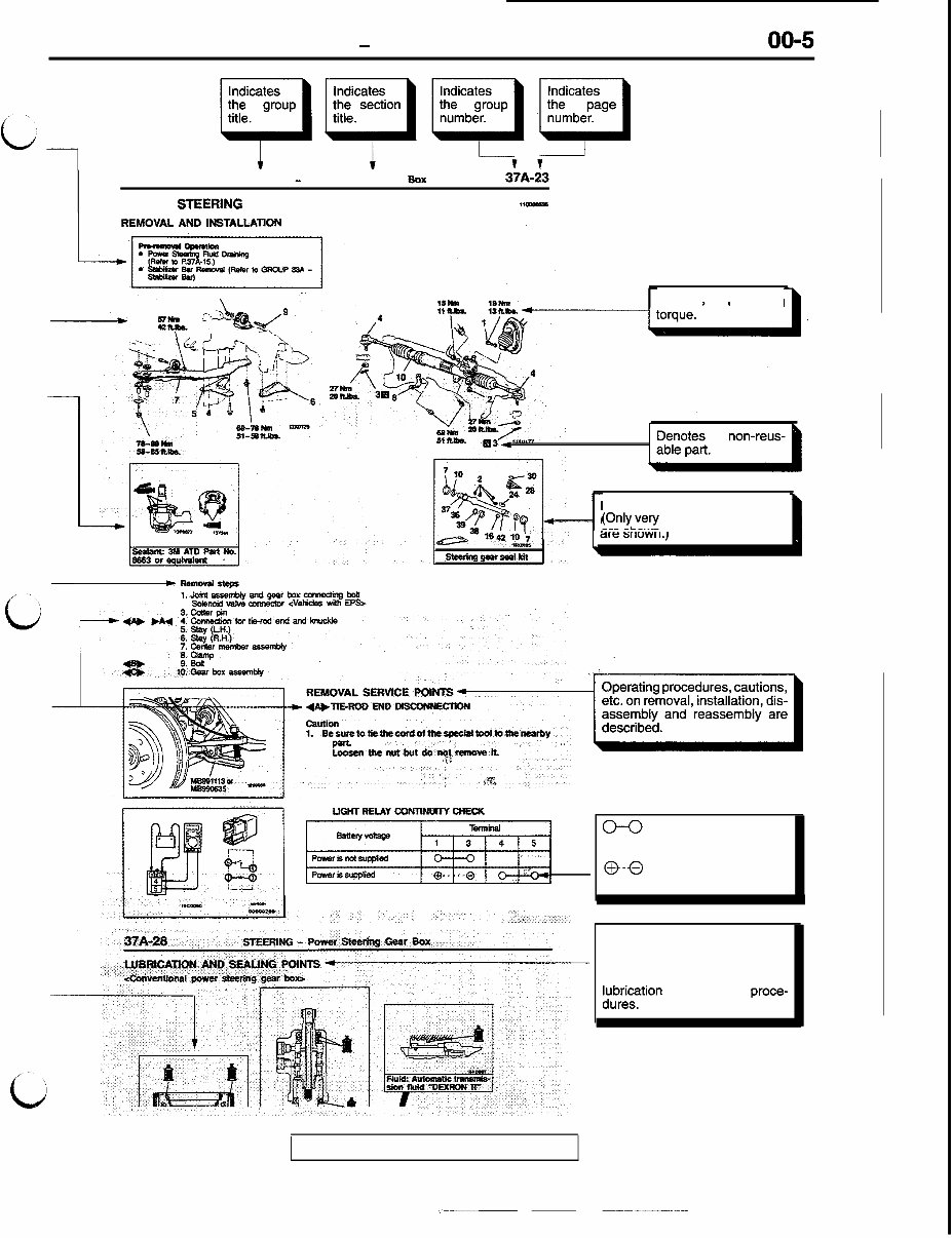
GENERAL - How to Use This Manual STEERING - Power Steering Gear Box 37A-23 POWER STEERtNG GEAR BOX ll- * ZL r, c \. / ?t?/ Denotes tightening Repair kit or set parts are shown. ~OJyL,“A~ frequently used parts ~Rnnovalstspr l.&iiassemblyandgfWboXcwnsctingbog 2. s&mid v&e OLxIlieEmr <VeNc!es wiU~ EPS> 2 EenthenutbutdonatremoveK ,<l FOG lJGl+l RELAY coNnNulTY CHECX ~ 0-0 indicates that there is continuity between the termi- nals. 0-0 indicates terminals to which battery voltage is applied. The title of the page (following the page on which the diagram of component parts is pres- ented) indicating the locations of l$riition and sealing proce- TSB Revision _j-- -------_-
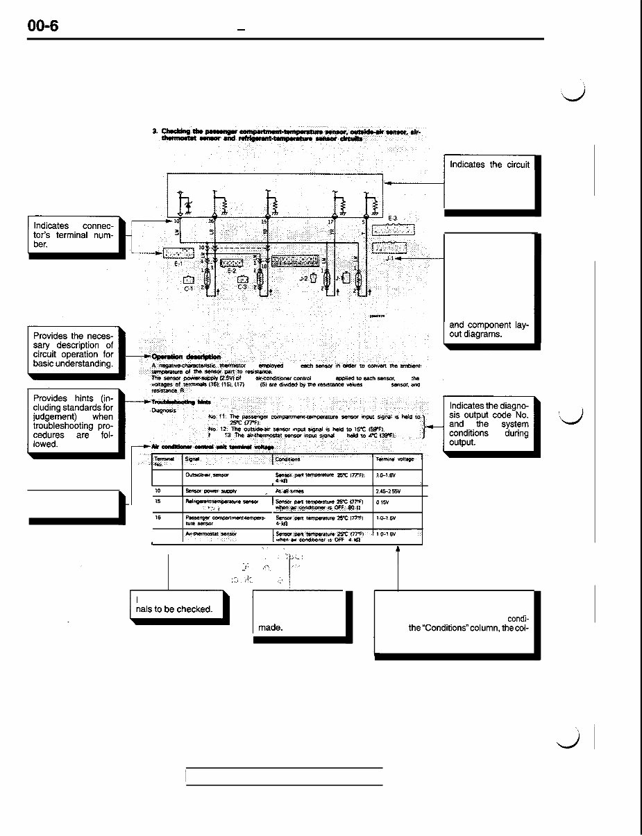
00-6 GENERAL - How to Use This Manual EXPLANATION OF THE TROUBLESHOOTING GUIDE ?#-wpphl @.$V) at the airsonddiormr ccmol unit is applied 10 each sewor. and the ntis (16). IX% 1171 and f51 am diitded by the reys- values of each sensor. and 11. The passerqet CMPanmenr~~ture smsw ityin SQnal rS held to 25-C v7-3. ..-. ,_. The olmfde.aw Ulnscu Input JiaMl is held to 15-c f5PFl. N O . 13. Tb ahthermo~ - imut WMI is hdd to SC l3SW. ti?emiSIM is mYwed for & myY in csder w eclmen ms amian ti?Mnsorplt10resi?asrre. s TzmiW w&age a.“. I I 5 OUtSdbW- saaar pa *- 25-c 177-n. m-l.sv 4kn Indicates the check to be made. t i f IV senrorpwrsusDfv ^ At~wnes 2.45-2 55v 15 RdrigQsm-rapanue SmsoOr 1 SaM Pm temosmun 2% (77-I 0 1511 . ,‘4.< k y$se~c++%i~nonnaOFF:BOD 16 passewm --w* SmawPmtarmaM * 25% f77-F) Iv-tsv NR- 4ko I 1 7 p-t- I smxmtampcrmrre2 whmarc.mdlt?amrroF 5~7~ crt 6% ~~ -1 --. :F 8161. _ _. 8 I ‘_ ” t ~C, a*,‘ Indicates the termi- Indicates the condi- tions underwhich the check should be diagram for checking (including the inter- face of the air condi- tioning control unit). Indicates the con- nector number. - Numbers are used in the operation de- scriptions only as necessary, and these numbers cor- respond to the num- bers used in harness Indicates the specification to be used for judgement of the check results. If there is no particular mention of condi- tionsin the”Conditions”column, thecol- umn Shows the specification under nor- mal conditions. 1 TSB Revision I
This Workshop Service Repair Manual for the 1992-1996 Mitsubishi 3000GT covers a wide range of essential topics, making it an invaluable resource for both professional mechanics and DIY enthusiasts. It includes high-quality diagrams and detailed instructions to effectively service and repair your Mitsubishi 3000GT.
The manual covers the following areas:
General
Engine
Fuel
Cooling
Intake And Exhaust
Emission Control
Clutch
Manual Transaxle
Automatic Transaxle
Propeller Shaft
Front Axle
Rear Axle
Wheel And Tire
Power Plant Mount
Front Suspension
Electronic Control Suspension
Rear Suspension
Service Brakes
Parking Brakes
Steering
4-wheel Steering System (4WS)
Body
Exterior
Interior
Supplemental Restraint System (SRS)
Heater, Air Conditioner And Ventilation
Engine Electrical
Chassis Electrical
This Service Repair Manual is available in a file format compatible with all versions of Windows & Mac. It is a comprehensive resource in English, and it is compatible with Adobe Reader. The instant accessibility of this manual saves on postage and packaging, making it a cost-effective and convenient solution for all your Mitsubishi 3000GT repair and service needs.
Don't miss out on the opportunity to enhance your understanding and maintenance of your Mitsubishi 3000GT. Get your hands on this invaluable resource now!