

2004-2007 Mitsubishi Endeavor Service & Repair Manual
What's Included?
Fast Download Speeds
Offline Viewing
Access Contents & Bookmarks
Full Search Facility
Print one or all pages of your manual
MITSUBISHI
Endeavor
BRAKES 9-10
ANTI-LOCK BRAKE
SYSTEM (ABS) 9-10
General Information 9-10
Wheel Speed Sensor Rings
(Toothed Rings) 9-11
Removal & Installation 9-11
Wheel Speed Sensors 9-11
Removal & Installation 9-11
BLEEDING THE BRAKE
SYSTEM 9-12
Bleeding Procedure 9-12
FRONT DISC BRAKES 9-12
Brake Caliper 9-12
Removal & Installation 9-12
Disc Brake Pads 9-13
Removal & Installation 9-13
PARKING BRAKE 9-15
Parking Brake Cables 9-15
Adjustment 9-15
Parking Brake Shoes 9-16
Adjustment 9-17
Removal & Installation 9-16
REAR DISC BRAKES 9-14
Brake Caliper 9-14
Removal & Installation 9-14
Disc Brake Pads 9-14
Removal & Installation 9-14
CHASSIS ELECTRICAL 9-17
AIR BAG (SUPPLEMENTAL
RESTRAINT SYSTEM) 9-17
Air Bag Module 9-18
Removal & Installation 9-18
General Information 9-17
Arming the System 9-18
Clockspring Centering 9-18
Disarming the System 9-18
Service Precautions 9-17
DRIVETRAIN.
Automatic Transaxle Assembly...9-19
Removal & Installation 9-19
Front Halfshaft 9-21
CV-boot Inspection 9-21
Removal & Installation 9-21
Rear Differential Carrier
Assembly 9-22
Removal & Installation 9-22
Rear Driveshaft 9-23
Removal & Installation 9-23
Rear Halfshaft 9-23
Removal & Installation 9-23
Rear Pinion Seal 9-24
Removal & Installation 9-24
Transfer Case Assembly 9-21
Removal & Installation 9-21
ENGINE COOLING 9-25
Engine Fan 9-25
Removal & Installation 9-25
Radiator 9-25
Removal & Installation 9-25
Thermostat 9-26
Removal & Installation 9-26
Water Pump 9-27
Removal & Installation 9-27
ENGINE ELECTRICAL 9-28
CHARGING SYSTEM 9-28
Alternator 9-28
Removal & Installation 9-28
IGNITION SYSTEM 9-28
Ignition Coil 9-28
Removal & Installation 9-28
Ignition Timing 9-29
Adjustment 9-29
Inspection 9-29
SparkPlugs 9-29
Removal & Installation 9-29
STARTING SYSTEM 9-30
Starter 9-30
Removal & Installation 9-30
Solenoid or Relay
Replacement 9-30
ENGINE MECHANICAL 9-30
Accessory Drive Belts 9-30
Accessory Belt Routing 9-30
Adjustment 9-30
Inspection 9-30
Removal & Installation 9-32
Camshaft and Valve Lifters 9-32
Inspection 9-32
Removal & Installation 9-32
Crankshaft Damper 9-34
Removal & Installation 9-34
Crankshaft Front Seal 9-34
Removal & Installation 9-34
Cylinder Head 9-35
Removal & Installation 9-35
Engine Assembly 9-35
Removal & Installation 9-35
Exhaust Manifold 9-37
Removal & Installation 9-37
Flexplate 9-39
Removal & Installation 9-39
Intake Manifold 9-40
Removal & Installation 9-40
Main Bearing Torque
Sequence 9-44
Oil Pan 9-42
Removal & Installation 9-42
Oil Pump 9-43
Inspection 9-43
Removal & Installation 9-43
Piston and Ring 9-44
Positioning 9-44
Rear Main Seal 9-44
Removal & Installation 9-44
Rocker Arms/Shafts 9-45
Removal & Installation 9-45
Timing Belt and Sprockets 9-46
Removal & Installation 9-46
Timing Belt Front Cover 9-45
Removal & Installation 9-45
Valve Covers 9-47
Removal & Installation 9-47
Valve Lash 9-47
Adjustment 9-47
ENGINE PERFORMANCE &
EMISSION CONTROL 9-49
Accelerator Pedal Position
(APP) Sensor 9-49
Location 9-49
Operation 9-49
Removal & Installation 9-49
Testing 9-49
QO MITSUBISHI
ENDEAVOR
Barometric Pressure (BARO)
Sensor 9-49
Location 9-49
Operation 9-49
Removal & Installation 9-49
Testing 9-49
Camshaft Position (CMP)
Sensor 9-50
LocafJon 9-50
Operation 9-50
Removal & Installation 9-50
Testing 9-50
Component Locations 9-49
Crankshaft Position (CKP)
Sensor 9-50
Location 9-50
Operation 9-51
Removal & Installation 9-51
Testing 9-51
Electric Fan Switch 9-51
Location 9-51
Operation 9-51
Removal & Installation 9-51
Testing 9-52
Engine Coolant Temperature
(ECT) Sensor 9-52
Location 9-52
Operation 9-52
Removal & Installation 9-52
Testing 9-52
Fuel Level Sending Unit 9-53
Location 9-53
Operation 9-53
Removal & Installation 9-53
Testing 9-53
Heated Oxygen (H02S) Sensor...9-54
Location 9-54
Operation 9-54
Removal & Installation 9-54
Testing 9-54
Intake Air Temperature
(IAT) Sensor 9-55
Location 9-55
Operation 9-55
Removal & Installation 9-55
Testing 9-55
Knock Sensor (KS) 9-55
Location 9-55
Operation 9-55
Removal & Installation 9-55
Testing 9-55
Malfunction Indicator
Light (MIL) 9-56
Reset Procedures 9-56
Manifold Absolute Pressure
(MAP) Sensor 9-56
Location... ....9-56
Operatio
Remova
Testing.
Mass Air F
Sensor...
Location
Operatio
Removal
Testing.
Oil Pressur
Location
Operatio
Testing.
Powertrain
Module (P
Location
Operatio
Removal
Testing.
Throttle Po
Sensor(Tf
Location
Operatior
Removal
Testing..
Vehicle Spe
Location
Operation
Removal
Testing..
9-56
& Installation 9-56
9.55
w(MAF)
9-56
9-56
9-56
& Installation 9-56
9-56
Sensor 9-56
9-56
9-56
9-57
ontrol
}M) 9-57
9-57
9-57
i Installation 9-57
9-57
ion
)) 9-57
9-57
9-57
i Installation 9-57
9-58
d Sensor (VSS) 9-58
9-58
9-58
Installation 9-58
....9-58
FUEL SYSTEM 9-59
GASOLINE FL
INJECTION i
Fuel Filter...
Removal
Fuel Pump..
Removal
Fuel Rail & I
Removal
Fuel System
Precaution:
Fuel Tank....
Removal
Idle Speed..
Adjustmer
Relieving Fu
Pressure...
Throttle Bod\l
EL
YSTEM 9-59
9-59
Installation 9-59
9-59
Installation 9-59
jectors 9-61
Installation 9-61
ervice
9-59
9-60
Installation 9-60
9-62
9-62
System
9-59
9-62
Installation 9-62
HEATING & />IR
CONDITIONING SYSTEM ....9-63
Blower Motor
Removal &
9-63
Installation 9-63
Heater Core 9-64
Removal & Installation 9-64
PRECAUTIONS 9-10
SPECIFICATIONS AND
MAINTENANCE CHARTS 9-4
Brake Specifications 9-8
Camshaft Specifications 9-6
Capacities 9-5
Crankshaft and Connecting
Rod Specifications 9-6
Engine and Vehicle
Identification 9-4
Engine Tune-Up
Specifications 9-4
Fluid Specifications 9-5
General Engine
Specifications 9-4
Piston and Ring
Specifications 9-6
Scheduled Maintenance
Intervals 9-8
Tire, Wheel and Ball Joint
Specifications 9-7
Torque Specifications 9-5
Valve Specifications 9-7
Wheel Alignment 9-7
STEERING 9-66
Power Rack & Pinion
Steering Gear 9-66
Removal & Installation 9-66
Power Steering Pump 9-67
Bleeding 9-68
Removal & Installation 9-67
Steering Linkage 9-69
Removal & Installation 9-69
SUSPENSION 9-69
FRONT SUSPENSION 9-69
Lower Ball Joint 9-69
Removal & Installation 9-69
Lower Control Arm 9-69
Control ARM Bushing
Replacement 9-69
Removal & Installation 9-69
MacPherson Strut 9-70
Overhaul 9-71
Removal & Installation 9-70
Stabilizer Bar 9-71
Removal & Installation 9-71
Steering Knuckle 9-72
Removal & Installation 9-72
MITSUBISHI
ENDEAVOR
9-3
Wheel Hub and Bearing 9-73
Adjustment 9-73
Removal & Installation 9-73
REAR SUSPENSION 9-74
Coil Spring 9-74
Removal & Installation 9-74
Control Arms/Links 9-74
Removal & Installation 9-74
Shock Absorber 9-76
Removal & Installation 9-76
Testing 9-76
Stabilizer Bar 9-77
Removal & Installation 9-77
Wheel Hub and Bearing 9-78
Adjustment 9-78
Removal & Installation 9-78
9-4
MITSUBISHI
ENDEAVOR
SPECIFICATIONS AND MAINTENANCE CHARTS
ENGINE AND VEHICLE IDENTIFICATION CHART
Engine Model Year
Code Liters (cc) Cu. In. Cyl. Fuel Sys. Engine Type Eng. Mfg. Code Year
3.8 (3828) 233.6 MFI
MFI Multi-port Fuel Injection
Mitsubishi 2007
2008
GENERAL ENCilNE SPECIFICATIONS
Engine Net
Displacement Engine Horsepower
Year Liters ID/VIN @ rpm
Net
Torque @ rpm
(ft. Ibs.)
Bore x Stroke
(in.)
Com-
pression
Ratio
Oil
Pressure
~ rpm
2007
2008
3.8
3.8
6G75/S
6G75/S
225@5000
225@5000
255@3750
255@3750
3.74x3.54
3.74x3.54
10.0:1
10.0:1
©
©
© 4.2 or more psi @ idle
43-100 @ 3500 rpm
22140JNDE_C0002
ENGINE TUNE4JP SPECIFICATIONS
Year
2007
2008
Engine
Displacement
Liters
3.8
3.8
Engine
IDA/IN
6G75/S
6G75/S
Spark Plugs
Gap
(in.)
0.028-0.031
0.028-0.031
Ignition
Timing
(deg.)
MT AT
—
®
ii :
Fuel
Pump
(psi)
47
47
Idle
Speed
(rpm)
MT AT
—
—
:2i
2
Valve
Clearance
In.
HYD
HYD
Ex.
HYD
HYD
HYD: Hydraulic
JJ Base ignition timing: 2-8 degrees BTDC
Actual ignition timing: 10 degrees BTDC
@ 580-780 rpm's
22140.ENDE C0003
MITSUBISHI
ENDEAVOR
9-5
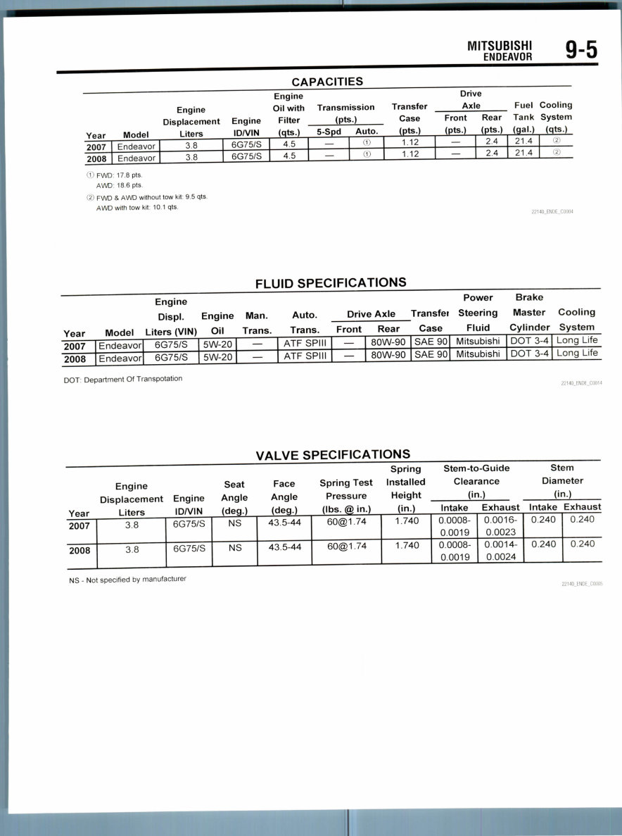
CAPACITIES
Engine
Displacement
Year Model Liters
2007 Endeavor 3.8
2008 Endeavor 3.8
Engine
IDA/IN
6G75/S
6G75/S
Engine
Oil with
Filter
(qts.)
4.5
4.5
Transmission Transfer
(pts.) Case
5-Spd
—
—
Auto. (pts.)
•1) 1.12
® 1.12
Drive
Axle
Front Rear
(pts.) (pts.)
— 2.4
— 2.4
Fuel
Tank
(gai.)
21 4
21.4
Cooling
System
(qts.)
2
2
'1 ' FWD: 17.8 pts.
AWD 18.6 pts.
(2) FWD & AWD without tow kit: 95 qts
AWD with tow kit: 10.1 qts.
1 : '.
FLUID SPECIFICATIONS
Engine
Displ. Engine Man. Auto.
Year Model Liters (VIN) Oil Trans. Trans.
2007
2008
Endeavor
Endeavor
6G75/S
6G75/S
5W-20
5W-20
—
—
ATF SPIN
ATF SPIN
Drive Axle
Front Rear
—
—
80W-90
80W-90
Power Brake
Transfei Steering Master Cooling
Case Fluid Cylinder System
SAE90
SAE90
Mitsubishi
Mitsubishi
DOT 3-4
DOT 3-4
Long Life
Long Life
• •. •.
VALVE SPECIFICATIONS
Spring
Engine Seat Face Spring Test Installed
Displacement Engine Angle Angle Pressure Height
Year Liters IDA/IN (deg.) (deg.) (Ibs. @ in.) (in.)
2007
2008
3.8
3.8
6G75/S
6G75/S
NS
NS
43.5-44
43.5-44
60@1.74
60@1.74
1.740
1.740
Stem-to-Guide Stem
Clearance Diameter
(in.) (in.)
Intake Exhaust Intake Exhaust
0.0008-
0.0019
0.0008-
0.0019
0.0016-
0.0023
0.0014-
0.0024
0.240
0.240
0.240
0.240
NS - Not specified by manufacturer
9-6
Year
2007
2008
MITSUBISHI
ENDEAVOR
Engine
Displ.
Liters
3.8
3.8
Engine
VIN
6G75/S
6G75/S
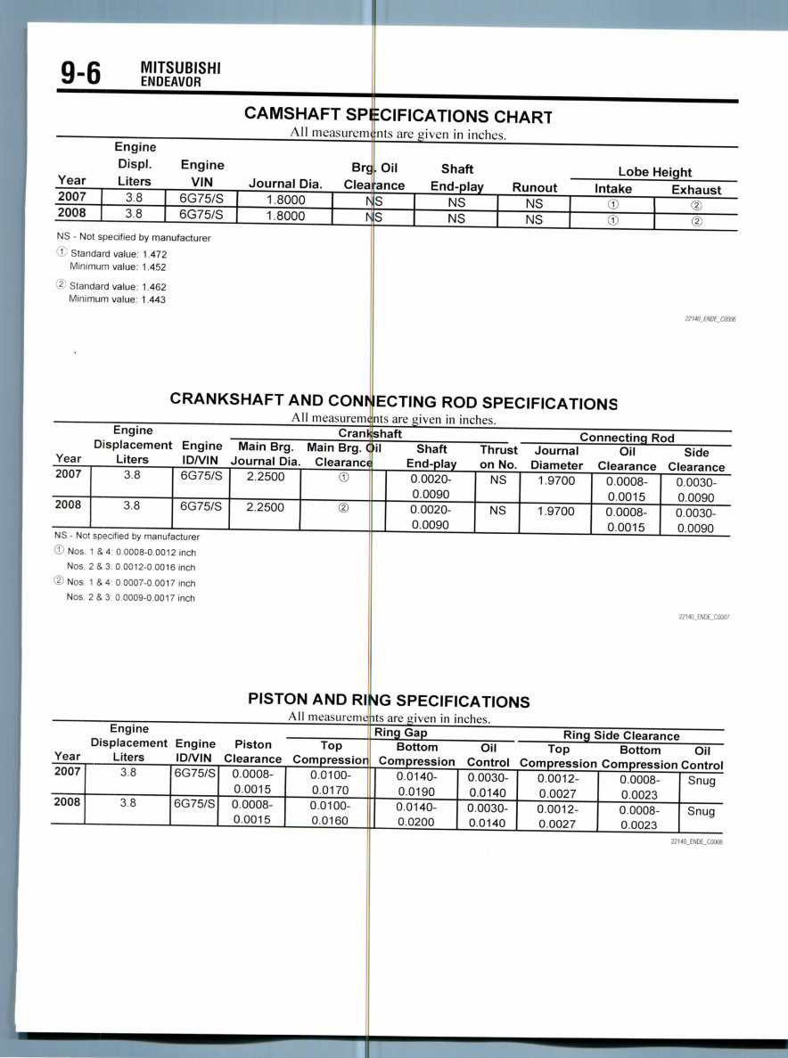
CAMSHAFT SPI
All measurerm
Journal Dia.
1.8000
1.8000
Brg
Clea
IN
IN
CIFICATIONS CHART
nts arc given in inches.
Oil
ance
S
S
Shaft
End-play
NS
NS
Lobe Height
Runout Intake Exhaust
NS (
NS C
j ''2;
") ''2;
NS - Not specified by manufacturer
1 Standard value: 1.472
Minimum value: 1.452
'2 Standard value: 1.462
Minimum value: 1.443
CRANKSHAFT AND CONK
All measurem
22140JNOE_C0006
ECTING ROD SPECIFICATIONS
nts are uiven in inches.
Engine
Displacement Engine
Year Liters IDA/IN
2007
2008
3.8
3.8
6G75/S
6G75/S
Crank
Main Brg. Main Brg. (
Journal Oia. Clearance
2.2500
2.2500
©
®
shaft Connecting Rod
il Shaft Thrust Journal Oil Side
End-play on No. Diameter Clearance Clearance
0.0020-
0.0090
0.0020-
0.0090
NS
NS
1.9700
1.9700
0.0008-
0.0015
0.0008-
0.0015
0.0030-
0.0090
0.0030-
0.0090
NS - Not specified by manufacturer
© Nos. 1 & 4 0.0008-0.0012 inch
Nos 2 & 3: 0.0012-0.0016 inch
© Nos. 1 & 4: 0.0007-0.0017 inch
Nos 2&3 00009-0 0017 inch
2214(LENDE_C0007
PISTON AND R
All measurem
>4G SPECIFICATIONS
Us are given in inches.
Engine
Displacement Engine Piston
Year Liters IDA/IN Clearance
2007
2008
3.8
3.8
6G75/S
6G75/S
0.0008-
0.0015
0.0008-
0.0015
Top
Compression
0.0100-
0.0170
0.0100-
0.0160
Ring Gap Ring Side Clearance
Bottom Oil Top Bottom Oil
Compression Control Compression Compression Control
0.0140-
0.0190
0.0140-
0.0200
0.0030-
0.0140
0.0030-
0.0140
0.0012-
0.0027
0.0012-
0.0027
0.0008-
0.0023
0.0008-
0.0023
Snug
Snug
22140_ENDE,C0008
MITSUBISHI
ENDEAVOR 9-7
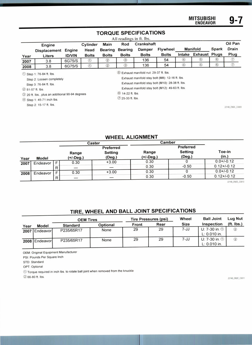
TORQUE SPECIFICATIONS
All readings in It. Ihs.
Year
2007
2008
Engine
Displacement Engine
Liters IDA/IN
3.8
3.8
6G75/S
6G75/S
Cylinder
Head
Bolts
©
©
Main
Bearing
Bolts
©
©
Rod
Bearing
Bolts
©
©
Crankshaft
Damper
Bolts
136
136
Flywheel Manifold
Bolts Intake Exhaust
54
54
0 ©
D (5J
Spark
Plugs
©
©
Oil Pan
Drain
Plug
©
©
© Step 1: 76-84 ft. Ibs.
Step 2: Loosen completely
Step 3: 76-84 ft. Ibs.
(D 51-57 ft. Ibs
© 20 ft. Ibs , plus an additional 90-94 degrees
© Step 1: 45-71 inch Ibs
Step 2: 15-17 ft. Ibs.
© Exhaust manifold nut: 29-37 ft. Ibs.
Exhaust manifold stay bolt (M8): 12-16 ft. Ibs.
Exhaust manifold stay bolt (M10): 28-38 ft. Ibs
Exhaust manifold stay bolt (M12): 49-63 ft. Ibs.
© 14-22 ft. Ibs.
©25-33 ft Ibs
22l4C_ENDE_C0009
WHEEL ALIGNMENT
Caster Camber
Preferred Preferred
Range Setting Range Setting Toe-in
Year Model (+/-Deg.) (Deg.) (+/-Deg.) (Deg.) (in.)
2007
2008
Endeavor
Endeavor
F
R
F
R
0.30
0.30
+3.00
+3.00
0.30
0.30
0.30
0.30
0
-0.50
0
-0.50
0.0+/-0.12
0.12+/-0.12
0.0+/-0.12
0.12+/-0.12
22140_ENOE_C0010
TIRE, WHEEL AND BALL JOINT SPECIFICATIONS
Year Model
2007
2008
Endeavor
Endeavor
OEM Tires Tire Pressures (psi)
Standard Optional Front Rear
P235/65R17
P235/65R17
None
None
29
29
29
29
Wheel Ball Joint Lug Nut
Size Inspection (ft. Ibs.)
7-JJ
7-JJ
U: 7-30 in ©
L: 0.010 in.
U: 7-30 in ©
L: 0.010 in.
@
©
OEM Original Equipment Manufacturer
PSI: Pounds Per Square Inch
STD: Standard
OPT: Optional
© Torque required in inch Ibs. to rotate ball joint when removed from the knuckle
©66-80 ft. Ibs.
22MO_ENDE_C0011
9-8
MITSUBISHI
ENDEAVOR
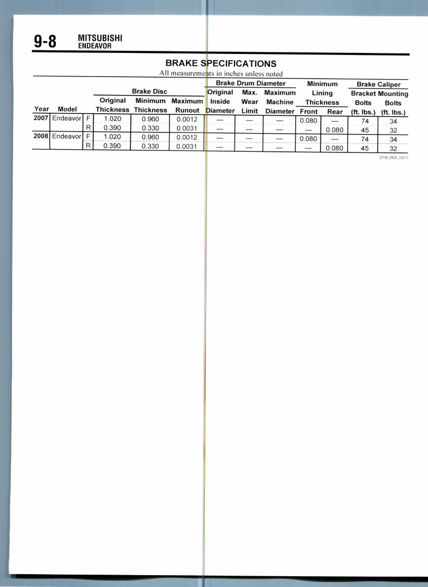
BRAKE S
All measureine
Year Model
2007
2008
Endeavor
Endeavor
F
R
F
R
Brake Disc
Original Minimum Maximum
Thickness Thickness Runout
1.020
0.390
1.020
0.390
0.960
0.330
0.960
0.330
0.0012
0.0031
0.0012
0.0031
=>ECIFICATIONS
its in inches unless noted
Brake Drum Diameter
f
riginal Max. Maximum
nside Wear Machine
ameter Limit Diameter
i
—
—
—
—
—
Minimum
Lining
Thickness
Front Rear
0.080
0.080
0.080
0.080
Brake Caliper
Bracket Mounting
Bolts Bolts
(ft. Ibs.) (ft. Ibs.)
74
45
74
45
34
32
34
32
MITSUBISHI
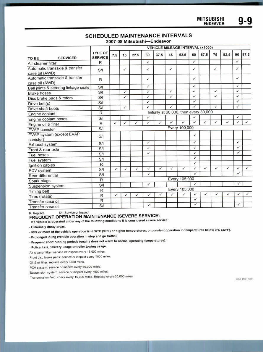
ENDEAVOR 9-9
SCHEDULED MAINTENANCE INTERVALS
2007-08 Mitsubishi—Endeavor
TO BE SERVICED
Air cleaner filter
Automatic transaxle & transfer
case oil (AWD)
Automatic transaxle & transfer
case oil (AWD)
Ball joints & steering linkage seals
Brake hoses
Disc brake pads & rotors
Drive belt(s)
Drive shaft boots
Engine coolant
Engine coolant hoses
Engine oil & filter
EVAP canister
EVAP system (except EVAP
canister)
Exhaust system
Front & rear axle
Fuel hoses
Fuel system
Ignition cables
PCV system
Rear differential
Spark plugs
Suspension system
Timing belt
Tires (rotate)
Transfer case oil
Transfer case oil
TYPE OF
SERVICE
R
S/l
R
S/l
S/l
S/l
S/l
S/l
R
S/l
R
S/l
S/l
S/l
S/l
S/l
S/l
R
S/l
S/l
R
S/l
R
R
R
S/l
VEHICLE MILEAGE INTERVAL (xlOOO)
7.5 15
•/
</
S
S
22.5 30
•/
S
S
•/
S
S
V
•/
37.5 45
S
•/
S
•/
52.5 60
S
S
</
S
•/
S
S
S
67.5 75
S
•/
V
•/
82.5 90
•/
S
S
v
S
•/
•/
•S
97.5
Initially at 60,000, then every 30,000
s •/ •/
</
S S •/ S
•/
•/ •/ S V
V
S •/
Every 100,000
s •S v1
•
•/
•/
S
•/
•/ </ V
S
•/
S
S
•/
•/
•/
S
•/ V S
S
•/
V
S
•/
V
Every 105,000
V S S
Every 105,000
s -/ S </
S
•/ V V S
•/
V
S •/ V V
•/
S
R Replace S/l: Service or Inspecl
FREQUENT OPERATION MAINTENANCE (SEVERE SERVICE)
If a vehicle is operated under any of the following conditions it is considered severe service:
- Extremely dusty areas.
- 50% or more of the vehicle operation is in 32°C (90°F) or higher temperatures, or constant operation in temperatures below 0°C (32*
- Prolonged idling (vehicle operation in stop and go traffic).
- Frequent short running periods (engine does not warm to normal operating temperatures).
- Police, taxi, delivery usage or trailer towing usage.
Air cleaner filter: service or inspect every 15,000 miles
Front disc brake pads: service or inspect every 7500 miles
Oil & oil filter: replace every 3750 miles
PCV system: service or inspect every 60,000 miles
Suspension system: service or inspect every 7500 miles
Transmission fluid: check every 15,000 miles Replace every 30,000 miles
F).
22HO_ENDE_C0013
PRECAUTIONS
Before servicing any vehicle, please be
sure to read all ot the following precautions,
which deal with personal safety, prevention
of component damage, and important points
to take into consideration when servicing a
motor vehicle:
• Never open, service or drain the radia-
tor or cooling system when the engine is
hot; serious burns can occur from the steam
and hot coolant.
• Observe all applicable safety precau-
tions when working around fuel. Whenever
servicing the fuel system, always work in
a well-ventilated area. Do not allow fuel
spray or vapors to come in contact with a
spark, open flame, or excessive heat (a hot
drop light, for example). Keep a dry chemi-
cal fire extinguisher near the work area.
Always keep fuel in a container specifically
designed for fuel storage; also, always
properly seal fuel containers to avoid the
possibility of fire or explosion. Refer to the
additional fuel system precautions later in
this section.
• Fuel injection systems often remain
pressurized, even after the engine has been
turned OFF. The fuel system pressure must
be relieved before disconnecting any fuel
lines. Failure to do so may result in fire
and/or personal injury.
• Brake fluid often contains polyglycol
ethers and polyglycols. Avoid contact with
the eyes and wash your hands thoroughly
after handling brake fluid. If you do get
brake fluid in your eyes, flush your eyes
with clean, running water for 15 minutes. If
eye irritation persists, or if you have taken
BRAKES
GENERAL INFORMATION
The ABS ensures directional stability and
control during hard braking. This ABS uses
a 4-sensor 4-channel system that controls
all four wheels independently of each other.
The EBD (Electronic Brake-force Distribu-
tion system) control has been installed to
provide the ideal braking force for the rear
wheels.
In ABS. electronic control is used so the
rear wheel brake hydraulic pressure during
braking is regulated by rear wheel control
solenoid valves in accordance with the
vehicle's rate of deceleration. The front and
rear wheel slippages are calculated from the
signals received from the various wheel
sensors. EBD control is a confrol system
which provides a high level of control for
brake fluid
medical assistai)
• The EPA vJ
with used enginl
of skin disorder!
should make evj
exposure to use
gloves should b
Wash your hand
skin areas as sot
sure to used entj
waterless hand
• All new vej
with an air bag \ Supplemental
Supplemental In
tern. The system
performing servj
components, std
panel componen
Failure to follow
dures could
deployment, pos
unnecessary sys
• Always we;
working with,
When carrying
sure the bag anc
away from your
deployed air bac
face the bag and
from the surface
motion of the mi
deployed. Refer
system
• Clean, higf
sealed container
internally, IMMEDIATELY seek
o
precautions
rns that prolonged contact
oil may cause a number
including cancer. You
'y effort to minimize your
engine oil. Protective
worn when changing oil.
and any other exposed
n as possible after expo-
ne oil. Soap and water, or
(jjeaner should be used,
ides are now equipped
ystem, often referred to as
estraint System (SRS) or
atable Restraint (SIR) sys-
must be disabled before
e on or around system
ring column, instrument
s, wiring and sensors.
;afety and disabling proce-
l in accidental air bag
ible personal injury and
em repairs,
r safety goggles when
or| around, the air bag system.
a non-deployed air bag, be
trim cover are pointed
ody. When placing a non-
on a work surface, always
trim cover upward, away
This will reduce the
dule if it is accidentally
the additional air bag
later in this section,
quality brake fluid from a
is essential to the safe and
proper operation of the brake system. You
should always buy the correct type of brake
fluid for your vehicle. If the brake fluid
becomes contaminated, completely flush the
system with new fluid. Never reuse any
brake fluid. Any brake fluid that is removed
from the system should be discarded. Also,
do not allow any brake fluid to come in con-
tact with a painted surface; it will damage
the paint.
• Never operate the engine without the
proper amount and type of engine oil; doing
so WILL result in severe engine damage.
• Timing belt maintenance is extremely
important. Many models utilize an
interference-type, non-freewheeling engine.
If the timing belt breaks, the valves in the
cylinder head may strike the pistons,
causing potentially serious (also time-
consuming and expensive) engine damage.
Refer to the maintenance interval charts for
the recommended replacement interval for
the timing belt, and to the timing belt sec-
tion for belt replacement and inspection.
• Disconnecting the negative battery
cable on some vehicles may interfere with
the functions of the on-board computer sys-
tem^) and may require the computer to
undergo a relearning process once the neg-
ative battery cable is reconnected.
• When servicing drum brakes, only
disassemble and assemble one side at a
time, leaving the remaining side intact for
reference.
• Only an MVAC-trained, EPA-certified
automotive technician should service the air
conditioning system or its components.
ANTI-LOCK BRAKE SYSTEM(ABS)
bral ing both vehicle
bility. The systeq
• Becauseth
mum rear wheel
vehicle load and
surface, the system
pedal depressior
vehicle is heavily
• Becauseth
brakes is reduce!
perature can be
brake applicatior
• Control val1
ing valve are not
Below some c
Anti-lock Brake
described.
System Chedk
the engine, a thudding
force and vehicle sta-
has the following features:
system provides the opti-
)raking force regardless of
he condition of the road
reduces the required
force, especially when the
loaded.
duty placed on the front
, the increases in pad tem-
(fjontrolled during front
to improve pad wear,
es such as the proportion-
equired.
the characteristics of the
ystem (ABS) are
Sound: When starting
sound can sometimes
be heard coming from the engine compart-
ment. This is a normal sound during the ABS
self-check.
ABS Operation Sounds and Sensa-
tions: During normal operation, the ABS
makes several sounds that may seem
unusual at first:
• A whining sound is caused by the ABS
hydraulic unit motor.
• When pressure is applied to the brake
pedal, the pulsation of the pedal causes a
scraping sound.
• When the brakes are applied firmly,
the ABS operates, rapidly applying and
releasing the brakes many times per sec-
ond. This repeated application and release
of braking forces can cause the suspension
to make a thumping sound and the tires to
squeak.
You're Reading a Preview
What's Included?
Fast Download Speeds
Offline Viewing
Access Contents & Bookmarks
Full Search Facility
Print one or all pages of your manual
$32.99
Viewed 29 Times Today


Secure transaction
What's Included?
Fast Download Speeds
Offline Viewing
Access Contents & Bookmarks
Full Search Facility
Print one or all pages of your manual
$32.99
Mitsubishi Endeavor 2004-2007 Service Repair Manual is a comprehensive guide covering all aspects of car repair and maintenance. Whether you are a professional mechanic or a DIY enthusiast, this manual provides detailed instructions for servicing your vehicle.
The manual is available in PDF format, allowing for easy reading, zooming, and printout. It is compatible with both Windows and MAC systems, ensuring accessibility for a wide range of users.


