

Mitsubishi Laser Talon & Eclipse Workshop Service Manual 1990, 1991, 1992, 1993, 1994, 1995, 1996, 1997, 1998, 1999 (6525 pages
What's Included?
Fast Download Speeds
Offline Viewing
Access Contents & Bookmarks
Full Search Facility
Print one or all pages of your manual
Includes Engine Transaxle
Overhaul
This Service Manual has been prepared with the
latest service information available at the time
of publication. It is subdivided into various group
categories and each section contains diagnostic,
disassembly, repair, and installation procedures
along with complete specifications and tightening
references. Use of this manual will aid in properly
performing any servicing necessary to maintain or
restore the high levels of performance and reliability
designed into these outstanding vehicles.
WE SUPPORT
VOLUNTARY TECHNICIAN
CERTIFICATION THROUGH
AUTOMOTIVE
SERVICE
EXCELLENCE
1996 Mitsubishi Motors Corporation Printed in U.S.A.
...
General ...................... .
Engine .............. ...........
Engine Lubrication ........ . .
Fuel ...................... ..
Engine . .. ......
Intake and Exhaust, . . ............ . .
Engine and Emission Control, ...
Clutch .........................
Manual Transaxle ..............
Automatic Transaxle ...........
Propeller .................
Front Axle .....................
Rear Axle ......................
Wheel and Tire .................
Power Plant Mount .............
Front Suspension ..............
Rear Suspension ..............
Service Brakes ................
Parking Brakes ................
Steering .......................
Body ..........................
Exterior .......................
Interior and Supplemental
Restraint System (SRS) ........
Heater, Air Conditioning and
Ventilation ....................
Alphabetical Index ..............
in Volume 2 “Electrical” of this paired Service Manu-
al.
REGARDING SERVICING OF SUPPLEMENTAL
RESTRAINT SYSTEM (SRS) EQUIPPED VEHICLES
WARNING!
(1) Improper service or maintenance of any component of the SRS, or any component,
can lead to personal injury or death to service personnel firing. of the bag)
or to the driver and passenger (from rendering the SRS inoperative).
(2) If it is possible that the SRS components are heat over baklng or
in drying after painting, remove the SRS components (air bag module, beforehand.
(3) Service or maintenance of any SRS component or SRS-related component be performed
only at an authorized MITSUBISHI dealer.
(4) MITSUBISHI dealer personnel must thoroughly review this manual, and Its GROUP
Supplemental Restraint System (SRS), before beginning any service or maintenance of any compo-
nent of the SRS or any SRS-related component.
NOTE
Section titles with the asterisks in the table of contents in each group indicate operations requiring
CONTENTS
GENERAL DATA AND SPECIFICATIONS ..
HOW TO USE THIS MANUAL ............. 3
Explanation of Manual Contents .............. 4
Model Indications ........................... 3
Maintenance, Repair and
Servicing Explanations. ...................... 3
Special Tool Note ........................... 3
Terms Definition ............................ 3
Tightening Torque Indication ................. 3
HOW TO USE TROUBLESHOOTING/
INSPECTION SERVICE POINTS ............ 6
Connector Inspection Service Points .......... 10
Connector Measurement Service Points ........ 9
How to Cope with Intermittent Malfunctions ... 11
How to Use the Inspection Procedures ....... 8
Inspection Service Points for a Blown Fuse ... 12
Troubleshooting Contents .................... 6
LUBRICATION AND MAINTENANCE ....... 33
MAIN SEALANT AND ADHESIVE TABLE ..
MAINTENANCE SERVICE .................. 38
Air Cleaner Element ........................ 39
Automatic Transaxle Fluid ................... 45
Ball Joint and Steering Linkage Seals ........ 50
Brake Hoses .. .
............................
50
Disc Brake Pads ............................ 49
Drive Belt (For Generator, Water Pump, Power
Steering Pump) ............................. 40
Drive Shaft Boots ........................... 50
Engine Coolant ............................. 48
Engine Oil .................................. 42
Engine Oil Filter ............................ 43
Evaporative Emission Control System .........
Exhaust System
............................. 54
Fuel Hoses ................................. 38
Fuel System
................................ 38
Ignition Cables
..............................
40
Manual Transaxle Oil ........................
Rear Axle Oil
............................
50
Rear Drum Brake Linings and
Rear Wheel Cylinders .......................
Spark Plugs
................................ 40
SRS System ............................... 51
Timing Belt
................................. 40
Transfer Oil ................................ 48
PRECAUTIONS BEFORE SERVICE ........ 20
RECOMMENDED LUBRICANTS
LUBRICANT CAPACITIES TABLE .......... 34
SCHEDULED MAINTENANCE TABLE .....
SPECIAL HANDLING INSTRUCTIONS FOR
AWD MODELS ............................ 26
TIGHTENING TORQUE
.................... 32
TOWING AND HOISTING
.................. 22
VEHICLE IDENTIFICATION
................. 13
Engine Model Stamping ..................... 15
Theft Protection
............................. 18
Vehicle Identification Code Chart Plate ....... 13
Vehicle Identification Number List ............ 14
Vehicle Identification Number Location ........ 13
Vehicle Information Code Plate. .............. 15
Vehicle Safety Certification Label ............. 15
NOTES
GENERAL How to Use This
HOW TO USE THIS MANUAL
MAINTENANCE, REPAIR AND
SERVICING EXPLANATIONS
This manual provides explanations, etc. concerning
procedures for the inspection, maintenance, repair
and servicing of the subject model. Unless other-
wise specified, each service procedure covers all
models. Procedures covering specific models are
identified by the model codes, or similar designation
(engine type, transaxle type, etc.). A description
of these designations is covered in this manual
under “VEHICLE IDENTIFICATION”.
ON-VEHICLE SERVICE
“On-vehicle Service” are procedures for performing
inspections and adjustments of particularly impor-
tant locations with regard to the construction and
for maintenance and servicing, but other inspec-
tions (for looseness, play, cracking, damage, etc.
must also be performed.
SERVICE PROCEDURES
The service steps are arranged in numerical order
and attention must to be paid in performing vehicle
service are described in detail in SERVICE POINTS.
TERMS DEFINITION
STANDARD VALUE
Indicates the value used as the standard for judging
the quality of a part or assembly on inspection
or the value to which the part or assembly is cor-
rected and adjusted. It is given by tolerance.
LIMIT
Indicates a maximum or minimum value, the part
or assembly should be kept within, in order to be
functional. This value is established outside the
standard value range.
REFERENCE VALUE
Indicates the adjustment value prior to starting the
work (presented in order to facilitate assembly and
adjustment procedures, and so they can be com-
pleted in a shorter time).
CAUTION
Indicates the presentation of information particularly
vital to the worker during the performance of mainte-
nance and servicing procedures in order to avoid
the possibility of injury to the worker, or damage
to component parts, or a reduction of component
or vehicle function or performance, etc..
TIGHTENING TORQUE INDICATION
The tightening torque shown in this manual is a
basic value with a tolerance of 10% except the
following cases when the upper. and
of tightening torque are given.
(1) The tolerance of the ‘basic value
10%.
(2) Special bolts or, the ‘like are
(3) Special tightening methods are used.
SPECIAL TOOL NOTE
When the MMC special tool is described, please
refer to the special tool
is located at the beginning of each group, for a
cross reference from the tool, number
to the special tool number that available in your
market.
.
MODEL INDICATIONS
The following abbreviations are used in this manual for classification of model types.
M/T Indicates the manual transaxle, or models equipped with the manual transaxle.
A/T Indicates the automatic transaxle, or models equipped with the automatic transaxle.
MFI: Indicates the fuel injection, or engines equipped with the fuel injection.
Turbo: Indicates the engine with turbocharger, or models equipped such an
Non-turbo: Indicates the engine without turbocharger, or models equipped with, such an engine.
FWD: Indicates the front wheel drive vehicles.
AWD: Indicates the all wheel drive vehicles.
ABS: Indicates the anti-lock braking system or models equipped with the braking
GENERAL How to Use This Manual
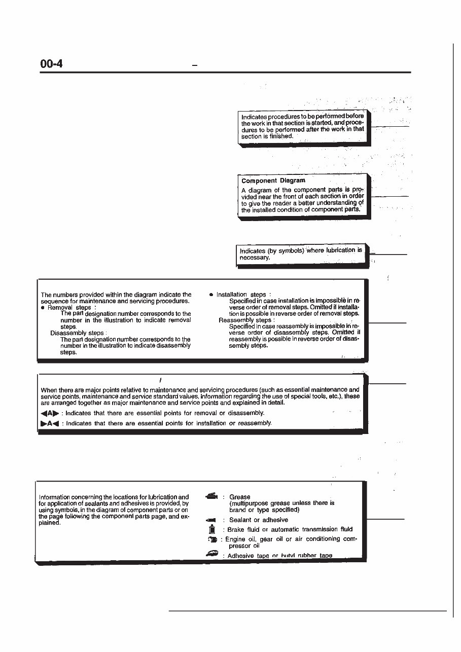
EXPLANATION OF MANUAL CONTENTS
Maintenance and Servicing Procedures
l
l
Classifications of Major Maintenance Service points
Symbols for Lubrication, Sealants and Adhesives
a
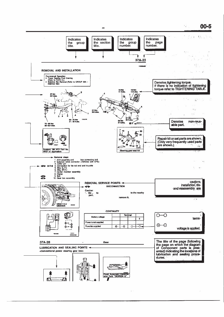
GENERAL How to Use This Manual
1
STEERING Power Steering Gear BOX
POWER STEERING GEAR BOX
6
gear
.
TIE-ROD END
. Operating procedures,
etc. on removal,
assembly
1. sun tie the cord of the special tool
described.
2. Loosen the nut but do not
FOG LIGHT RELAY CHECK
I indicates that there is
1 3 4
, continuity’ between the
o---a nals.
supplied
indicates terminals‘ to
which battery
STEERING Power Steering Box
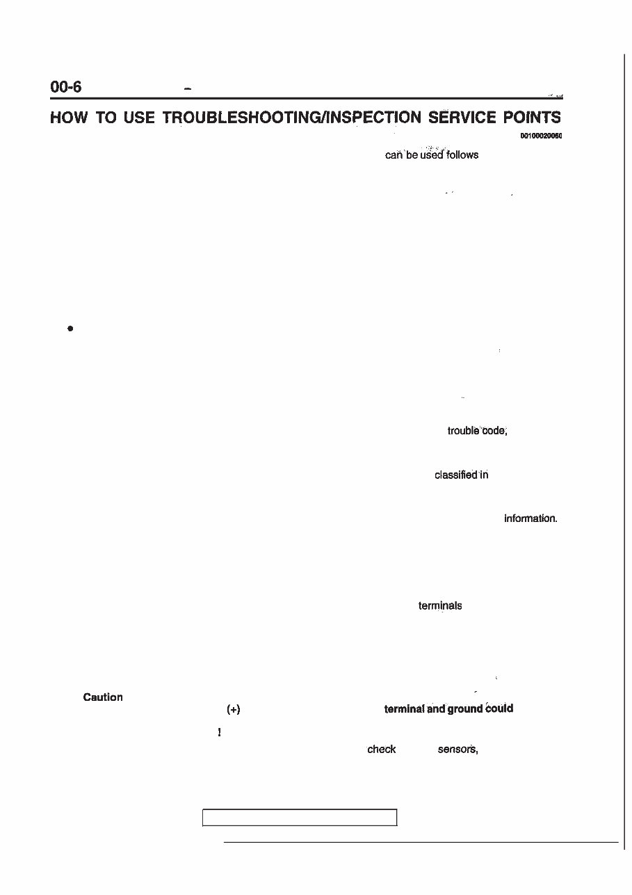
GENERAL How to Use Troubleshooting/Inspection Service Points
Troubleshooting of electronic control systems for which the scan tool the basic outline
described below. Furthermore, even in systems for which the scan tool cannot be used, part of these
systems still follow this outline.
TROUBLESHOOTING CONTENTS
1. STANDARD FLOW OF DIAGNOSTIC TROUBLESHOOTING
The main procedures for diagnostic troubleshooting are shown.
2. SYSTEM OPERATION AND SYMPTOM VERIFICATION TESTS
If verification of the trouble symptoms is difficult, procedures for checking operation and verifying
trouble symptoms are shown.
3. DIAGNOSTIC FUNCTION
The following diagnostic functions are shown.
l , Method of reading diagnostic trouble codes
Method of erasing diagnostic trouble codes
l Input inspection service points
4. INSPECTION CHART FOR DIAGNOSTIC TROUBLE CODES
5. INSPECTION PROCEDURE FOR DIAGNOSTIC TROUBLE CODES
Indicates the inspection procedures corresponding to each diagnostic trouble code. (Refer to the
next page on how to use the inspection procedures.)
6. INSPECTION CHART FOR TROUBLE SYMPTOMS
If there are trouble symptoms, even though the scan tool displays no diagnostic inspection
procedures for each trouble symptom will be found by means of this chart.
7. INSPECTION PROCEDURE FOR TROUBLE SYMPTOMS
Indicates the inspection procedures corresponding to each trouble symptoms the Inspection
Chart for Trouble Symptoms. (Refer to the next page on how to use the inspection procedures.)
8. DATA LIST REFERENCE TABLE
Inspection items and normal judgement values have been provided in this chart as reference
9. CHECK AT ECU TERMINALS
Terminal numbers for the ECU connectors, inspection items and standard values have been provided
in this chart as reference information.
Terminal Voltage Checks
1. Connect a needle-nosed wire probe or paper clip to a voltmeter probe.
2. Insert the needle-nosed wire probe into each of the ECU connector from the wire side,
and measure the voltage while referring to the check chart.
NOTE
1. Measure voltage with the ECU connectors connected.
2. You may find it convenient to pull out the ECU to make it easier to reach the connector
terminals.
3. Checks don’t have to be carried out in the order given in the chart.
Short-circuiting the positive probe between a connector damage
the vehicle wiring, the sensor, the ECU, or all three.
Use care to prevent this
3. If voltage readings differ from Normal Condition values, related actuators, and
wiring, then replace or repair.
TSB Revision
GENERAL How to Use Troubleshooting/Inspection Service Points
4. After repair or replacement, recheck the voltmeter to confirm the repair
the problem.
Terminal Resistance and Continuity Checks
1. Turn the ignition switch to off.
2. Disconnect the ECU connector.
3. Measure the resistance and check for continuity between the terminals of the ECU
connector while referring to the check chart.
NOTE
Checks don’t have to be carried out in the order given in the chart.
Cautlon
If resistance and continuity checks are performed the wrong terminals, damage
vehicle wiring, sensors, ECU, and/or ohmmeter may occur.
Use care to prevent this!
4. If the ohmmeter shows any deviation from the Normal Condition value, check the corresponding
5.
sensor, actuator and related electrical wiring, then repair or replace.
After repair or replacement, recheck with the ohmmeter to confirm that the repair
the problem.
10. INSPECTION PROCEDURES USING AN OSCILLOSCOPE
When there are inspection procedures using an oscilloscope, these are listed here.
,
TSB Revision
GENERAL How to Use Service
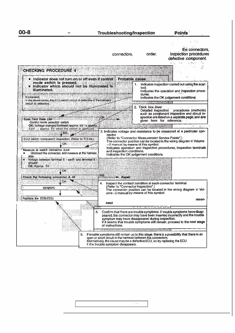
HOW TO USE THE INSPECTION PROCEDURES
.
. ,
The causes of a high frequency of problems occurring in electronic circuitry are generally
components, the ECU and the harnesses between in that These
follow this order, and they first try to discover a problem with a connector or a
17
Check trouble
I
Caution
After carrying out connector inspection, always be sure to
the connector as it was before.
so check the harness.
and check
HARNESS INSPECTION
Check for an open or short circuit in the harness between the terminals which were defective according
to the connector measurements. Carry out this inspection while referring to Volume 2 Electrical manual.
Here, “Check harness between power supply and terminal xx” also includes checking for blown fuses.
For inspection service points when there is a blown fuse, refer to “Inspection Service Points for a Blown
Fuse”.
MEASURES TO TAKE AFTER REPLACING THE ECU
If the trouble symptoms have not disappeared even after replacing the ECU, repeat the inspection procedure
from the beginning.
TSB Revision
,
You're Reading a Preview
What's Included?
Fast Download Speeds
Offline Viewing
Access Contents & Bookmarks
Full Search Facility
Print one or all pages of your manual
$35.99
$46.99
Viewed 73 Times Today


Secure transaction
What's Included?
Fast Download Speeds
Offline Viewing
Access Contents & Bookmarks
Full Search Facility
Print one or all pages of your manual
$35.99
$46.99
This Mitsubishi Laser Talon & Eclipse Workshop Service Manual is a comprehensive guide for maintaining and repairing your vehicle.
- Models Covered:
- 1990 Mitsubishi Laser Talon
- 1991 Mitsubishi Laser Talon
- 1992 Mitsubishi Laser Talon
- 1993 Mitsubishi Laser Talon
- 1994 Mitsubishi Laser Talon
- 1995 Mitsubishi Laser Talon
- 1996 Mitsubishi Laser Talon
- 1997 Mitsubishi Laser Talon
- 1998 Mitsubishi Laser Talon
- 1999 Mitsubishi Laser Talon
- 1990 Mitsubishi Eclipse
- 1991 Mitsubishi Eclipse
- 1992 Mitsubishi Eclipse
- 1993 Mitsubishi Eclipse
- 1994 Mitsubishi Eclipse
- 1995 Mitsubishi Eclipse
- 1996 Mitsubishi Eclipse
- 1997 Mitsubishi Eclipse
- 1998 Mitsubishi Eclipse
- 1999 Mitsubishi Eclipse
With over 6500 pages, this service manual provides detailed step-by-step instructions, diagrams, and illustrations to help you perform various maintenance and repair tasks on your Mitsubishi Laser Talon or Eclipse. Whether you are a DIY enthusiast or a professional mechanic, this manual will be your trusted companion in keeping your vehicle in excellent condition.


