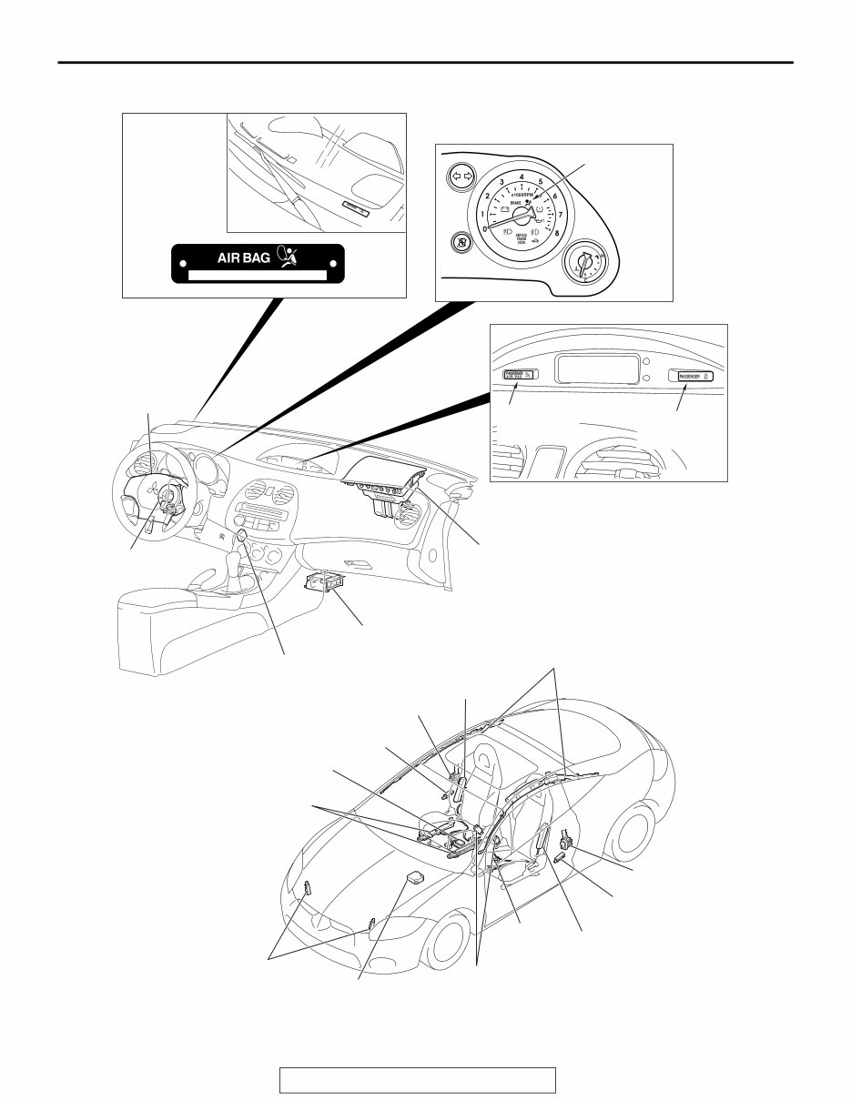
GENERAL DESCRIPTION TSB Revision SUPPLEMENTAL RESTRAINT SYSTEM (SRS) 52B-3 GENERAL DESCRIPTION M1524000100837 NOTE: In this manual, the part names are changed from the names in owner's manual into the following names. . • Driver’s seat position sensor → Seat slide sensor • Passenger’s seat weight sensor → Occupant classification sensor • Seat belt buckle switch → Seat belt switch • Passenger air bag off indicator → Passenger air bag OFF indicator light • Front passenger seat belt warning light → Pas- senger seat belt warning light . WARNING Improper service could result in serious injury of the service personnel or the pas- senger. . The SRS is designed to supplement the front seat belts. It reduces injury to the driver(s) and the front passenger(s) by deploying air bag(s) in case of a head-on collision. The SRS front air bags form an advanced air bag system together with sensors at the vehicle and sen- sors attached to the front seats. . Side-airbag systems in the front seats are activated when side impacts exceed criteria to protect the occupants’ upper bodies. . The curtain air bag systems are activated when side impacts applied to the vehicle exceed criteria, to pro- tect the heads of the occupants in the front seats. . The seat belts with pre-tensioner work simulta- neously with the SRS. The seat belt incorporating the pre-tensioner automatically winds the seat belt upon front impact to reduce forward shifting of the driver’s and passenger’s. The seat belt use status controls the activation and deactivation of the pre-tensioner. . The SRS consists of six air bag modules, SRS air bag control unit (SRS-ECU), two front impact sen- sors, two side impact sensors, SRS warning light, passenger air bag OFF indicator light, passenger seat belt warning light, clock spring, seat belt pre-tensioner, seat belt switch, seat slide sensor, occupant classification sensor and occupant classifi- cation-ECU. Air bag modules are located in the cen- ter of the steering wheel and above the glove box. Side-airbags are located inside the front seatback assemblies. The curtain air bag module consists of an air bag, an inflator, and the fixing gear relating to those parts, and is installed in the roof side sections (from the driver's and the passenger's front pillars to the rear pillars). Each air bag consists of a folded air bag and an inflator unit. The SRS-ECU placed on the forefront of the floor monitors the system and has a front air bag safing G-sensor, front air bag analog G-sensor and a side-airbag safing G-sensor. The front impact sensor is assembled in the radiator sup- port panel to monitor impact in case of front impact. The side impact sensors inside the center pillars monitor the shock incurred by the sides of the vehi- cle. The SRS warning light on the combination meter indicates the operational status of the SRS. The clock spring is installed in the steering column. The seat belt pre-tensioner is built into the driver's and passenger's front seat belt retractor. The seat slide sensor is installed at the seat adjuster section of the driver seat in order to detect the driver seat slide position. The occupant classification sensor is installed underneath a rail of the passenger seat to detect the load on the seat. The passenger air bag OFF indicator light is installed to the lower left of the multi-center display, and illuminates when the pas- senger seat air bag is inactive. The passenger seat belt warning light is installed to the lower right of the multi-center display, and illuminates when the pas- senger is not wearing the seat belt. The seat belt switch detects whether the seat belt is used. Only authorized service personnel should do work on or around the SRS components. Those service per- sonnel should read this manual carefully before start- ing any such work. .
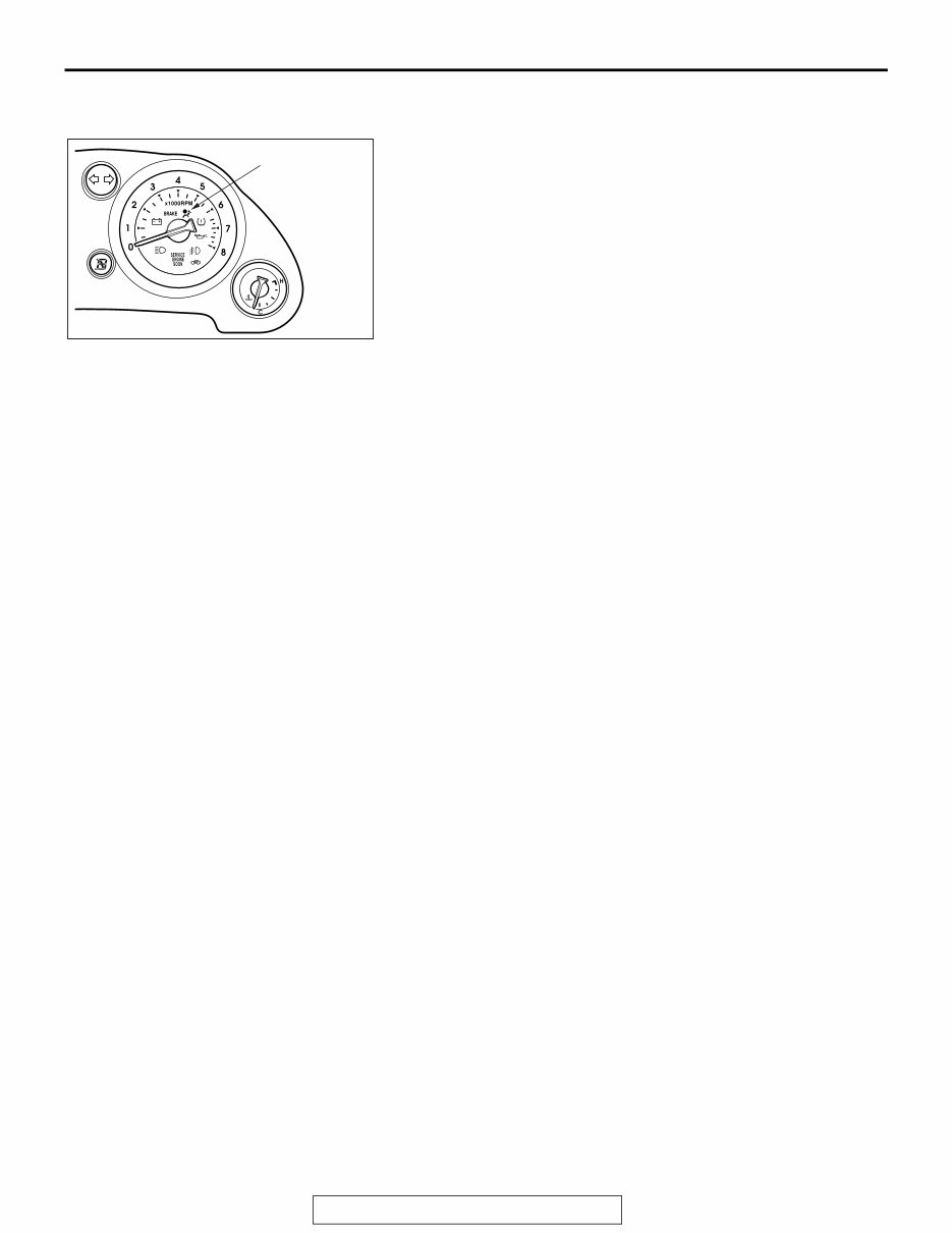
GENERAL DESCRIPTION TSB Revision SUPPLEMENTAL RESTRAINT SYSTEM (SRS) 52B-4 ON-BOARD DIAGNOSTIC/SRS WARNING LIGHT FUNCTION The diagnosis unit monitors the SRS system and stores data concerning any detected faults in the system. When the ignition switch is in "ON" or "START" position, the SRS warning light should illuminate for about seven seconds and then turn "OFF." That indicates that the SRS system is in operational order. If the SRS warning light does any of the following, immediate inspection by an authorized dealer is needed: 1. The SRS warning light does not illuminate as described above. 2. The SRS warning light stays on for more than seven seconds. 3. The SRS warning light illuminates while driving. If a vehicle's SRS warning light is in any of these three condi- tions, the SRS system must be inspected, diagnosed and ser- viced in accordance with this manual. AC405758 SRS WARNING LIGHT AB
GENERAL DESCRIPTION TSB Revision SUPPLEMENTAL RESTRAINT SYSTEM (SRS) 52B-5 CONSTRUCTION DIAGRAM NOTE: This construction diagram shows the general view of the SRS components. For details, refer to "Schematic(P.52B-9), "Configuration Diagrams(P.52B-12), " and "Circuit Diagram(P.52B-14)". AC406537 AC205757 AC405690 AC405758 AC405787 AC406218 AC405689 VEHICLE IDENTIFICATION CODE CHART PLATE SRS WARNING LIGHT PASSENGER AIR BAG OFF INDICATOR LIGHT PASSENGER SEAT BELT WARNING LIGHT CLOCK SPRING DRIVER'S AIR BAG MODULE SRS-ECU DATA LINK CONNECTOR (FOR SCAN TOOL) PASSENGER'S (FRONT) AIR BAG MODULE FRONT IMPACT SENSOR SIDE-AIRBAG MODULE SIDE IMPACT SENSOR SEAT BELT WITH PRE-TENSIONER SEAT SLIDE SENSOR SEAT BELT SWITCH SRS-ECU OCCUPANT CLASSIFICATION SENSOR SIDE IMPACT SENSOR SIDE-AIRBAG MODULE SEAT BELT WITH PRE-TENSIONER OCCUPANT CLASSIFICATION-ECU CURTAIN AIR BAG MODULE AC
2000-2006 Mitsubishi Eclipse, Eclipse Spyder OEM Service & Repair Manual
Models Covered:
Mitsubishi Eclipse
Mitsubishi Eclipse Spyder
Engines Covered:
2.4L 4-cylinder (4G64)
3.0L V6 (6G72)
3.8L V6 (6G75)
Transmissions Covered:
F5M42 – 5-speed manual
F5M51 – 5-speed manual
F6MBA – 6-speed manual
F4A – 4-speed automatic
F5A – 5-speed auto
The 2000-2006 Mitsubishi Eclipse, Eclipse Spyder OEM Service & Repair Manual provides full coverage of all factory procedures for the third-generation Eclipse platform (including Spyder convertible variants). It supports maintenance and overhaul work for all major engine options and transmissions used throughout the 2000–2006 production run.
This OEM manual includes verified service data for the 2.4L SOHC inline-4 (4G64), the 3.0L SOHC V6 (6G72), and the 3.8L SOHC V6 (6G75), along with comprehensive transmission coverage ranging from 5-speed and 6-speed manuals to multiple automatic transaxle variants, including INVECS-II electronically controlled models.
Whether you're servicing drivetrain components, inspecting clutch packs, or diagnosing transmission behavior tied to torque converter stall ratios or speed sensor output, this manual includes detailed specifications, gear ratios, clutch data, and shift control schemes across all variants.
Body & Interior – including convertible top mechanisms (Spyder)
Electrical System Diagnostics
Troubleshooting Charts and Torque Specs
This OEM manual is indispensable for any technician or Eclipse owner performing serious repair work across 2000-2006 models. It ensures proper fitment and correct factory procedures for powertrain, driveline, and control systems across both coupe and convertible platforms.
Printable: Yes Language: English Compatibility: Works on all devices Requirements: PDF reader
Recently Viewed
5,521,897Happy Clients
2,594,462eManuals
1,120,453Trusted Sellers
15Years in Business
Price:
Actual Price:
2000-2006 Mitsubishi Eclipse, Eclipse Spyder OEM Service & Repair Manual