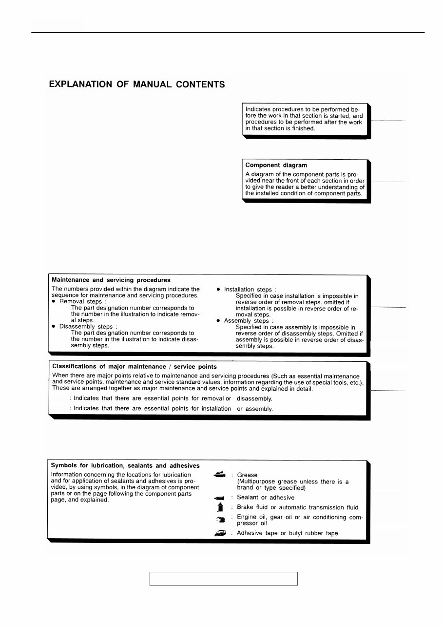
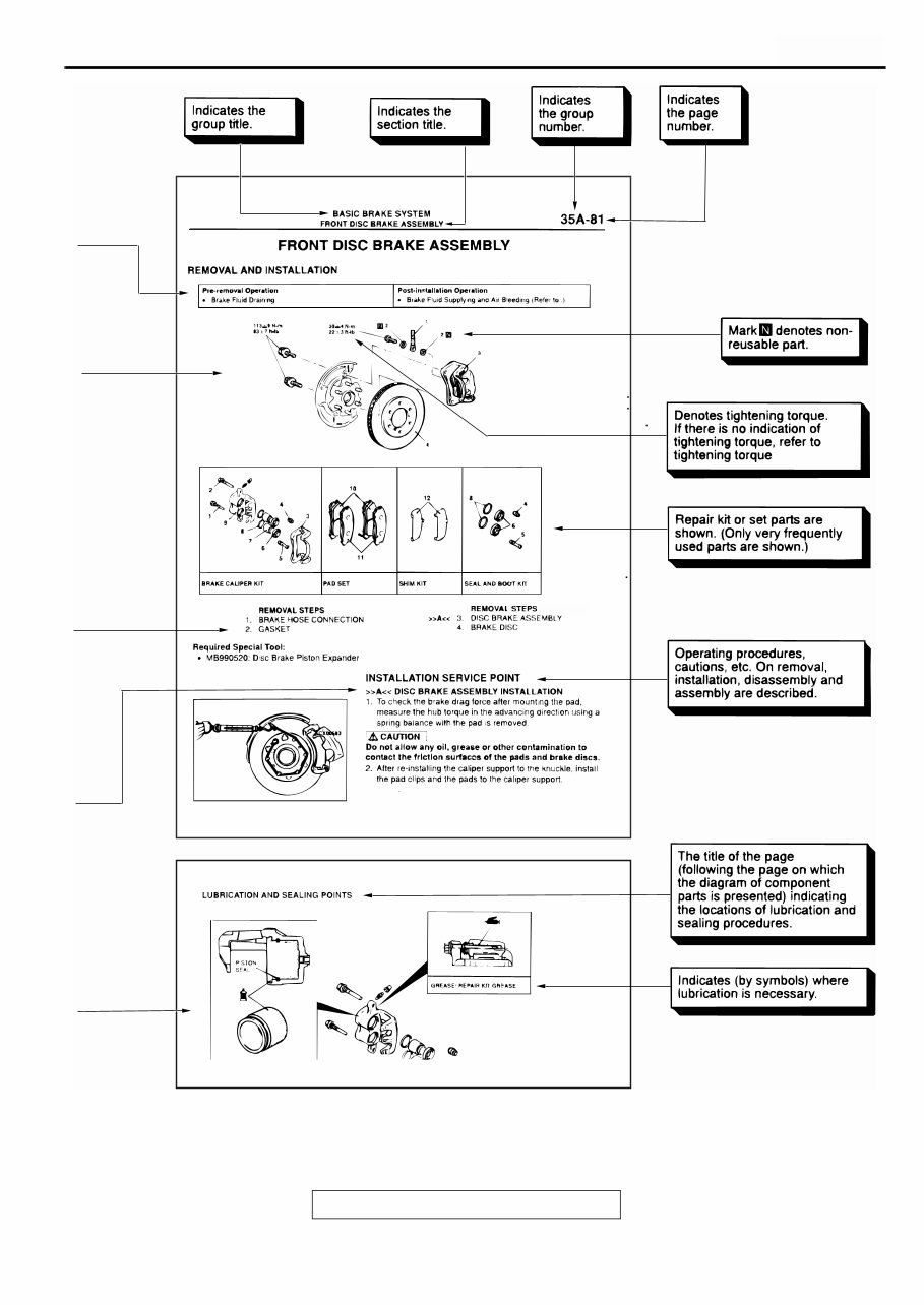
HOW TO USE THIS MANUAL TSB Revision GENERAL <BODY AND CHASSIS> 00-3 . HOW TO USE THIS MANUAL M1001000100110 MAINTENANCE, REPAIR AND SERVICING EXPLANATIONS This manual provides explanations, etc. concerning procedures for the inspection, maintenance, repair and servicing of the subject model. Unless otherwise specified, each service procedure covers all models. Procedures covering specific models are identified by the model codes, or similar designation (engine type, transaxle type, etc.). A description of these designations is covered in this manual under "VEHICLE IDENTIFICATION." ON-VEHICLE SERVICE "ON-VEHICLE SERVICE" are procedures for performing inspections and adjustments of particularly important locations with regard to the construction and for maintenance and servicing, but other inspections (for looseness, play, cracking, damage, etc.) must also be performed. SERVICE PROCEDURES The service steps are arranged in numerical order. Attention must to be paid in performing vehicle service are described in detail in SERVICE POINTS. DEFINITION OF TERMS STANDARD VALUE Indicates the value used as the standard for judging the quality of a part or assembly on inspection or the value to which the part or assembly is corrected and adjusted. It is given by tolerance. LIMIT Shows the standard for judging the quality of a part or assembly on inspection and means the maximum or minimum value within which the part or assembly must be kept functionally or in strength. It is a value established outside the range of standard value. REFERENCE VALUE Indicates the adjustment value prior to starting the work (presented in order to facilitate assembly and adjustment procedures, and so they can be completed in a shorter time). DANGER, WARNING, AND CAUTION DANGER, WARNING, and CAUTION call special attention to a necessary action or to an action that must be avoided. The differences among DANGER, WARNING, and CAUTION are as follows: • If a DANGER is not followed, the result is severe bodily harm or even death. • If a WARNING is not followed, the result could be bodily injury. • If a CAUTION is not followed, the result could be damage to the vehicle, vehicle components or service equipment. TIGHTENING TORQUE INDICATION The tightening torque indicates a median and its tolerance by a unit of N⋅m (in-lb) or N⋅m (ft-lb). For fasteners with no assigned torque value, refer to P.00-30. SPECIAL TOOL NOTE Only MMC special tool part numbers are called out in the repair sections of this manual. Please refer to the special tool cross reference chart, which is located in the service manual at the beginning of each group, for a cross reference from the MMC special tool number to the special tool number that is available in your market. MODEL INDICATIONS The following abbreviations are used in this manual for classification of model types. M/T:Indicates manual transaxle, or models equipped with manual transaxle. A/T: Indicates automatic transaxle, or models equipped with automatic transaxle. MFI: Indicates multiport fuel injection, or engines equipped with multiport fuel injection. A/C: Indicates air conditioning. 2.4L Engine: Indicates the 2.4 liter <4G64> engine, or a model equipped with such an engine. 3.0L Engine: Indicates the 3.0 liter <6G72> engine, or a model equipped with such an engine. PCM: Powertrain control module ECM: Engine control module SWS: Simplified Wiring System
HOW TO USE THIS MANUAL TSB Revision GENERAL <BODY AND CHASSIS> 00-4 ACX00859 <<A>> >>A<< AD
HOW TO USE THIS MANUAL TSB Revision GENERAL <BODY AND CHASSIS> 00-5 ACX00860 AC (continued) .
TROUBLESHOOTING GUIDELINES TSB Revision GENERAL <BODY AND CHASSIS> 00-6 TROUBLESHOOTING GUIDELINES M1001008800102 VERIFY THE COMPLAINT • Make sure the customer's complaint and the service writer's work order description are understood before starting work. • Make sure the correct operation of the system is understood. Read the service manual description to verify any aspect of normal system operation. • Operate the system to see the symptoms. Look for other symptoms that were not reported by the customer, or on the work order, that may be related to the problem. DETERMINE POSSIBLE CAUSES Compare the confirmed symptoms to the diagnostic symptom indexes to get to the right diagnosis procedure. If the confirmed symptoms can not be found on any symptom index, determine other possible causes. • Analyze the system diagrams and list all possible causes for the problem symptoms. • Rank all these possible causes in order of probability, based on how much of the system they cover, how likely they are to be the cause, and how easy they will be to check. Be sure to take experience into account. Consider the causes of similar problems seen in the past. The list of causes should be ranked in order from general to specific, from most-likely to least-likely, and from easy-to-check to hard-to-check. FIND THE PROBLEM After the symptoms have been confirmed, and probable causes have been identified, the next step is to make step-by-step checks of the suspected system components, junctions, and links in logical order. Use the diagnostic procedures in the service manual whenever possible. Follow these procedures carefully to avoid missing an important step in the diagnosis sequence. It might be the skipped step that leads to the solution of the problem. If the service manual doesn't have step-by-step procedures to help diagnose the problem, come up with a series of checks based on the ranked list of probable causes. Troubleshooting checks should be made in the order that the list of causes was ranked: • general to specific • most-likely to least-likely • easy-to-check to hard-to-check REPAIR THE PROBLEM When the step-by-step troubleshooting checks find a fault, perform the proper repairs. Make sure to fix the root cause of the problem, not just the symptom. Just fixing the symptom, without fixing the root cause, will cause the symptom to eventually return. VERIFY THE REPAIR After repairs are made, recheck the operation of the system to confirm that the problem is eliminated. Make sure to check the system thoroughly. Sometimes new problems are revealed after repairs have been made. HOW TO USE TROUBLESHOOTING/INSPECTION SERVICE POINTS M1001000200098 Troubleshooting of electronic control systems for which the scan tool can be used follows the basic outline described below. Even in systems for which the scan tool cannot be used, part of these systems still follow this outline. TROUBLESHOOTING CONTENTS 1. STANDARD FLOW OF DIAGNOSTIC TROUBLESHOOTING Troubleshooting strategy are shown. 2. SYSTEM OPERATION AND SYMPTOM VERIFICATION TESTS If verification of the symptoms is difficult, procedures for checking operation and verifying symptoms are shown. 3. DIAGNOSTIC FUNCTION The following trouble code diagnosis are shown. • How to read diagnostic trouble codes • How to erase diagnostic trouble codes • Input inspection service points
HOW TO USE TROUBLESHOOTING/INSPECTION SERVICE POINTS TSB Revision GENERAL <BODY AND CHASSIS> 00-7 4. DIAGNOSTIC TROUBLE CODE CHART 5. SYMPTOM CHART If there are symptoms, even though the results of inspection using the scan tool show that all diagnostic trouble codes are normal, inspection procedures for each symptom will be found by using this chart. 6. DIAGNOSTIC TROUBLE CODE PROCEDURES Indicates the inspection procedures corresponding to each diagnostic trouble code. (Refer to P.00-7.) 7. SYMPTOM PROCEDURES Indicates the inspection procedures corresponding to each symptoms classified in the Symptom Chart. (Refer to P.00-7.) 8. SERVICE DATA REFERENCE TABLE Inspection items and normal judgement values have been provided in this chart as reference information. 9. CHECK AT ECU TERMINALS Terminal numbers for the ECU connectors, inspection items and standard values have been provided in this chart as reference information. Terminal Voltage Checks 1. Connect a needle-nosed wire probe to a voltmeter probe. CAUTION Short-circuiting the positive (+) probe between a connector terminal and ground could damage the vehicle wiring, the sensor, the ECU, or all three. Use care to prevent this! 2. Insert the needle-nosed wire probe into each of the ECU connector terminals from the wire side, and measure the voltage while referring to the check chart. NOTE: Measure voltage with the ECU connectors connected. You may find it convenient to pull out the ECU to make it easier to reach the connector terminals. Checks don't have to be carried out in the order given in the chart. 3. If voltage readings differ from normal condition values, check related sensors, actuators, and wiring, then replace or repair. 4. After repair or replacement, recheck with the voltmeter to confirm that the repair has corrected the problem. Terminal Resistance and Continuity Checks 1. Turn the ignition switch to "LOCK" (OFF) position. 2. Disconnect the ECU connector. CAUTION If resistance and continuity checks are performed on the wrong terminals, damage to the vehicle wiring, sensors, ECU, and/or ohmmeter may occur. Use care to prevent this! 3. Measure the resistance and check for continuity between the terminals of the ECU harness-side connector while referring to the check chart. NOTE: Checks don't have to be carried out in the order given in the chart. 4. If the ohmmeter shows any deviation from the Normal Condition value, check the corresponding sensor, actuator and related electrical wiring, then repair or replace. 5. After repair or replacement, recheck with the ohmmeter to confirm that the repair has corrected the problem. 10. INSPECTION PROCEDURES USING AN OSCILLOSCOPE When there are inspection procedures using an oscilloscope, these are listed here. HOW TO USE THE INSPECTION PROCEDURES The causes of many of problems occurring in electric circuitry are generally the connectors, components, the ECU and the harnesses between connectors, in that order. These inspection procedures follow this order. They first try to discover a problem with a connector or a defective component.
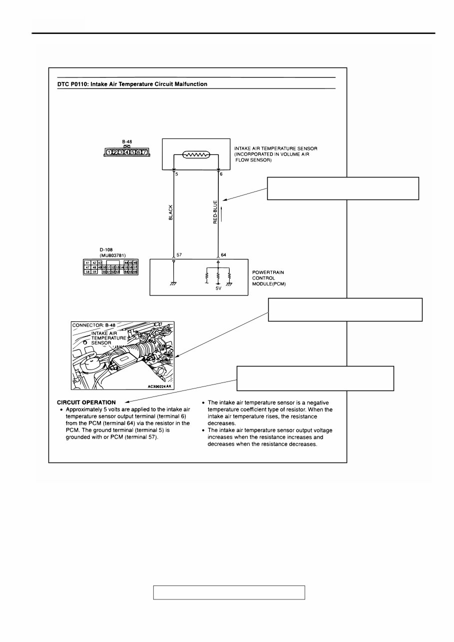
HOW TO USE TROUBLESHOOTING/INSPECTION SERVICE POINTS TSB Revision GENERAL <BODY AND CHASSIS> 00-8 ACX00861 AC (1) Relevanta circuit(s) of the component which the DTC indicates are described. (2) Shows the position of the connector(s) which are referred to in the above circuit(s). (3) Explains about the operation principle of the component or its relevant parts in that circuit.
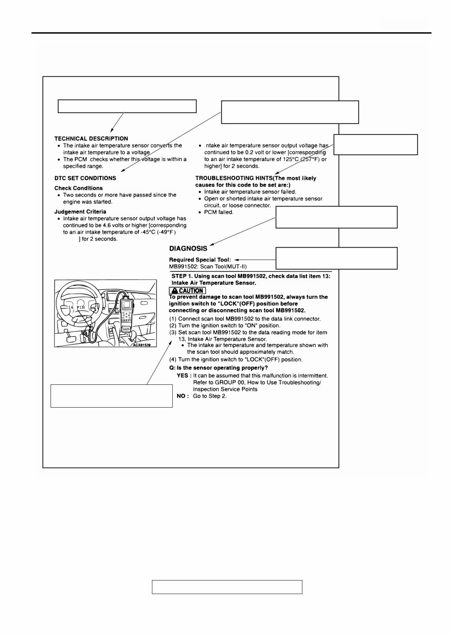
HOW TO USE TROUBLESHOOTING/INSPECTION SERVICE POINTS TSB Revision GENERAL <BODY AND CHASSIS> 00-9 HARNESS INSPECTION Check for an open or short circuit in the harness between the terminals which were faulty according to the connector measurements. Carry out this inspection while referring to GROUP 00E, Harness Connector Inspection P.00E-2. Here, "Check harness between power supply and terminal xx" also includes checking for blown fuse. For inspection service points when there is a blown fuse, refer to "Inspection Service Points for a Blown Fuse P.00- 15." ACX00862 (4) Explains about technicai details. (5) Describes the conditions for that DTC being set (stored). (6) Describes possible cause(s)for that DTC. (7) Describes the diagnosis procedure for that DTC. (8) Describes the special tool(s) necessary for that DTC. (9) Describes the inspection procedure for that DTC step by step. AC lower or .
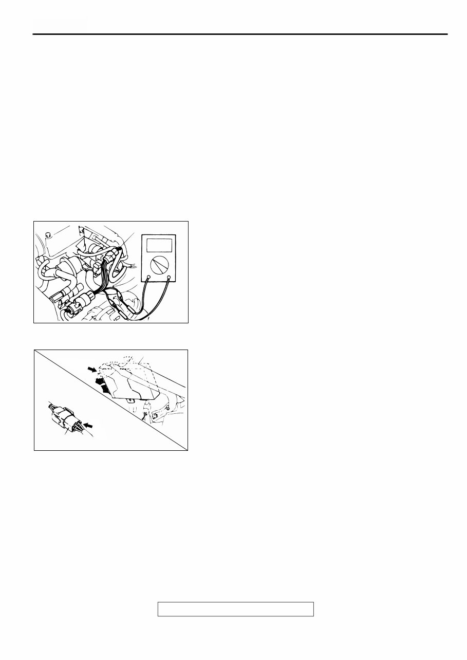
HOW TO USE TROUBLESHOOTING/INSPECTION SERVICE POINTS TSB Revision GENERAL <BODY AND CHASSIS> 00-10 MEASURES TO TAKE AFTER REPLACING THE ECU If the trouble symptoms have not disappeared even after replacing the ECU, repeat the inspection procedure from the beginning. CONNECTOR MEASUREMENT SERVICE POINTS Turn the ignition switch to the "LOCK" (OFF) position when connecting and disconnecting the connectors. Turn the ignition switch to "ON" when measuring if there are no instructions to the contrary. IF INSPECTING WITH THE CONNECTOR CONNECTED (WITH CIRCUIT IN A CONDITION OF CONTINUITY) Required Special Tool: MD998459: Test Harness Waterproof Connectors Be sure to use special tool, MB998459. Never insert a test probe from the harness side, as this so will reduce the waterproof performance and result in corrosion. Ordinary (non-waterproof) Connectors Check by inserting the test probe from the harness side. Note that if the connector (control unit, etc.) is too small to permit insertion of the test probe, it should not be forced; use the backprobing tool for this purpose. IF INSPECTING WITH THE CONNECTOR DISCONNECTED <When Inspecting a Female Pin> • From front side of the connector Required Special Tool: MB991219: Inspection Harness (Included in MB991223, Harness Set) ACX00863 AB MD998459 AC001606 AB CONNECTOR
This 2002 MITSUBISHI ECLIPSE Service and Repair Manual is a comprehensive guide for maintaining and fixing your vehicle. Whether you are a DIY enthusiast or a professional mechanic, this manual will provide you with detailed instructions and diagrams to assist you in servicing and repairing your 2002 Mitsubishi Eclipse.
Included in this manual are step-by-step procedures for various tasks, such as engine overhaul, transmission repair, electrical system troubleshooting, and more. The manual covers all aspects of service and repair, ensuring that you have the knowledge and confidence to successfully complete any necessary repairs on your Eclipse.
This manual is specifically designed for the 2002 Mitsubishi Eclipse model and is compatible with the following versions:
2002 Mitsubishi Eclipse GS Coupe 2-Door
2002 Mitsubishi Eclipse GT Coupe 2-Door
2002 Mitsubishi Eclipse Spyder Convertible 2-Door
With its clear instructions and detailed illustrations, this manual will be your go-to resource for maintaining and repairing your 2002 Mitsubishi Eclipse. Invest in this Service and Repair Manual today and ensure the longevity and performance of your vehicle.