1997 - 1999 Mitsubishi Eclipse Spyder Service Repair Manual
What's Included?
Lifetime Access
Fast Download Speeds
Offline Viewing
Access Contents & Bookmarks
Full Search Facility
Print one or all pages of your manual
BACKUP Service Manual’ ECIB’SE/ ECII’SE Volume 1 Chassis & Body Includes Engine & Transaxle Overhaul FOREWORD This Service Manual has been prepared with the latest service information available at the time of publication. It is subdivided into various group categories and each section contains diagnostic, disassembly, repair, and installation procedures along with complete specifications and tightening references. Use of this manual will aid in properly performing any servicing necessary to maintain or restore the high levels of performance and reliability designed into these outstanding vehicles. This BACKUP DSM manual IS to be used ONLY as a BACKUP. Please DO NOT REDISTRIBUTE WHOLE SECTIONS. This BACKUP was sold to you under the fact that you do indeed OWN a GENUINE DSM MANUAL. It CANNOT BE considered a REPLACEMENT (Unless your original manual was lost or destroyed.) Please See README.N or README.HTML for additional Information. Thank you. G~mm~emymanual@hotma~l.com WE SUPPORT VOLUNTARY TECHNICIAN CERTIFICATION THROUGH National lnritlfulc for AUTOMOTIVE SERVICE EXCELLENCE MITSUBISHI MOTOR SALES OF AMERICA. Inc. Mitsubishi Motors Corporation reserves the right to make changes in design or to make additions to or improvements in its products without imposing any obligations upon itself to install them on its products previously manufactured. @ 1996 Mitsubishi Motors Corporation Printed in U.S.A. -I GRWB ‘HVPEX. ’ ... “wy+ General ...................... ..?, . ,.,m Engine .............. .:. ........... “ mm Engine Lubrication ........ . :‘1.‘ J . “” m Fuel ...................... ..i .. I’ mm Engine Cooli.ng, . ‘. .. .,I ...... ; ; ;-I. * :m Intake and Exhaust, . . ............ . . ” :I- Engine and Emission Control, ... F ;im Clutch ......................... Manual Transaxle .............. Automatic Transaxle ........... Propeller Shaft ................. Front Axle ..................... ma Rear Axle ...................... ma Wheel and Tire ................. Power Plant Mount ............. m Front Suspension .............. Rear Suspension .............. m Service Brakes ................ Parking Brakes ................ mm Steering ....................... Body .......................... mm Exterior ....................... Interior and Supplemental Restraint System (SRS) ........ Heater, Air Conditioning and Ventilation .................... Alphabetical Index .............. NOTE: Electrical system information is contained in Volume 2 “Electrical” of this paired Service Manu- al.
WAR,NINGS REGARDING SERVICING OF SUPPLEMENTAL RESTRAINT SYSTEM (SRS) EQUIPPED VEHICLES _, ” WARNING! (1) Improper service or maintenance of any component of the SRS, or any SRS-related component, can lead to personal injury or death to service personnel .(from inadviertent firing. of the alr bag) or to the driver and passenger (from rendering the SRS inoperative). (2) If it is possible that the SRS components are subjected’to heat over 93°C 4290 In baklng or in drying after painting, remove the SRS components (air bag module, SRS-EClJ) beforehand. (3) Service or maintenance of any SRS component or SRS-related component must be performed only at an authorized MITSUBISHI dealer. (4) MITSUBISHI dealer personnel must thoroughly review this manual, and especially Its GROUP 526 - Supplemental Restraint System (SRS), before beginning any service or maintenance of any compo- nent of the SRS or any SRS-related component. NOTE & / Section titles with the asterisks (‘) in the table of contents in each group indicate operations requiring warnings. .I __ I ., ‘\ , :j ‘( ‘ ‘_ <’ .a II I ,: i” *a ,” I. . . ._
f.)fJ$$ I” L ,, #_v,: .,,.,, 1/_ ?,.*A.- GENERAL CONTENTS oolo9ooo171 GENERAL DATA AND SPECIFICATIONS .. .28 HOW TO USE THIS MANUAL ............. 3 Explanation of Manual Contents .............. 4 Model Indications ........................... 3 Maintenance, Repair and Servicing Explanations. ...................... 3 Special Tool Note ........................... 3 Terms Definition ............................ 3 Tightening Torque Indication ................. 3 HOW TO USE TROUBLESHOOTING/ INSPECTION SERVICE POINTS ............ 6 Connector Inspection Service Points .......... 10 Connector Measurement Service Points ........ 9 How to Cope with Intermittent Malfunctions ... 11 How to Use the Inspection Procedures ....... 8 Inspection Service Points for a Blown Fuse ... 12 Troubleshooting Contents .................... 6 LUBRICATION AND MAINTENANCE ....... 33 MAIN SEALANT AND ADHESIVE TABLE .. .55 MAINTENANCE SERVICE .................. 38 Air Cleaner Element ........................ 39 Automatic Transaxle Fluid ................... 45 Ball Joint and Steering Linkage Seals ........ 50 Brake Hoses .. . ............................ 50 Disc Brake Pads ............................ 49 Drive Belt (For Generator, Water Pump, Power Steering Pump) ............................. 40 Drive Shaft Boots ........................... 50 Engine Coolant ............................. 48 Engine Oil .................................. 42 Engine Oil Filter ............................ 43 Evaporative Emission Control System ......... 39 Exhaust System ............................. 54 Fuel Hoses ................................. 38 Fuel System ................................ 38 Ignition Cables .............................. 40 Manual Transaxle Oil ........................ 44 Rear Axle Oil ............................ 50 Rear Drum Brake Linings and Rear Wheel Cylinders ....................... 49 Spark Plugs ................................ 40 SRS System ............................... 51 Timing Belt ................................. 40 Transfer Oil ................................ 48 PRECAUTIONS BEFORE SERVICE ........ 20 RECOMMENDED LUBRICANTS .AND LUBRICANT CAPACITIES TABLE .......... 34 SCHEDULED MAINTENANCE TABLE ..... .37 SPECIAL HANDLING INSTRUCTIONS FOR AWD MODELS ............................ 26 TIGHTENING TORQUE .................... 32 TOWING AND HOISTING .................. 22 VEHICLE IDENTIFICATION ................. 13 Engine Model Stamping ..................... 15 Theft Protection ............................. 18 Vehicle Identification Code Chart Plate ....... 13 Vehicle Identification Number List ............ 14 Vehicle Identification Number Location ........ 13 Vehicle Information Code Plate. .............. 15 Vehicle Safety Certification Label ............. 15
00-2 NOTES ‘Jp& “, / i ‘_ :.‘: .e” “. ,” ,/: 9, “I : I. I d: . ‘1 ,_ ,.“1, > : ,:, , ‘1.. < I,r : .I I,” * ,.. r ,L- ,: 1 .” p: ,%,“? : 4, Crr / :,.. ‘, ,, P i . ,. . . . itr ,/ : . . B I ,,, L. ;j ,, ‘r ..I : . a1 ,. (“2,. _, r I” ,; “” U’ c , ,, ‘i ., 1 : ” . _: ‘/ I- ,‘i I. “\al’? ;, : : .-, ,I. x i c ,‘” t, ,, .-I :, .! ‘T ,a / L _I L: i.. ,.* ,,C ; i . 7* _:
GENERAL - How to Use This Manual HOW TO USE THIS MANUAL ‘* 3 ” mu%& MAINTENANCE, REPAIR AND SERVICING EXPLANATIONS This manual provides explanations, etc. concerning procedures for the inspection, maintenance, repair and servicing of the subject model. Unless other- wise specified, each service procedure covers all models. Procedures covering specific models are identified by the model codes, or similar designation (engine type, transaxle type, etc.). A description of these designations is covered in this manual under “VEHICLE IDENTIFICATION”. ON-VEHICLE SERVICE “On-vehicle Service” are procedures for performing inspections and adjustments of particularly impor- tant locations with regard to the construction and for maintenance and servicing, but other inspec- tions (for looseness, play, cracking, damage, etc. ) must also be performed. SERVICE PROCEDURES The service steps are arranged in numerical order and attention must to be paid in performing vehicle service are described in detail in SERVICE POINTS. TERMS DEFINITION STANDARD VALUE Indicates the value used as the standard for judging the quality of a part or assembly on inspection or the value to which the part or assembly is cor- rected and adjusted. It is given by tolerance. LIMIT Indicates a maximum or minimum value, the part or assembly should be kept within, in order to be functional. This value is established outside the standard value range. REFERENCE VALUE Indicates the adjustment value prior to starting the work (presented in order to facilitate assembly and adjustment procedures, and so they can be com- pleted in a shorter time). CAUTION Indicates the presentation of information particularly vital to the worker during the performance of mainte- nance and servicing procedures in order to avoid the possibility of injury to the worker, or damage to component parts, or a reduction of component or vehicle function or performance, etc.. TIGHTENING TORQUE INDICATION The tightening torque shown in this manual is a basic value with a tolerance of f 10% except the following cases when the upper. and foyer iim@ of tightening torque are given. (1) The tolerance of the ‘basic value is tiithin f ’ 10%. (2) Special bolts or, the ‘like are ‘in @se:, (3) Special tightening methods are used. ” ” / SPECIAL TOOL NOTE ,_. _:, When the MMC special tool is described, please refer to the special tool cross~ referencechart, Which is located at the beginning of each group, for a cross reference from the MMGspecial tool, number to the special tool number that is available in your market. ,I “” . ,, ‘> MODEL INDICATIONS The following abbreviations are used in this manual for classification of model types. M/T : Indicates the manual transaxle, or models equipped with the manual transaxle. A/T : Indicates the automatic transaxle, or models equipped with the automatic transaxle. MFI: Indicates the multiport fuel injection, or engines equipped with the multiport fuel injection. Turbo: Indicates the engine with turbocharger, or models equipped ,with such an engi.ne. Non-turbo: Indicates the engine without turbocharger, or models equipped with, such an engine. FWD: Indicates the front wheel drive vehicles. AWD: Indicates the all wheel drive vehicles. ABS: Indicates the anti-lock braking system or models equipped with the anti4ock braking &em. ,( t,. ,*,, 2: .y; 3’
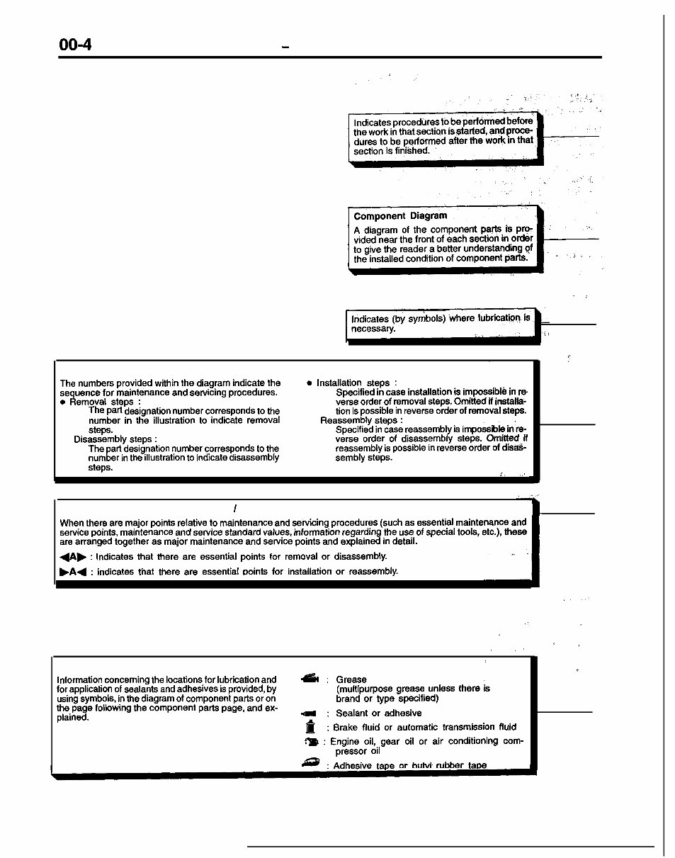
00-4 GENERAL - How to Use This Manual EXPLANATION OF MANUAL CONTENTS ^ i Maintenance and Servicing Procedures . The numbers provided within the diagram indicate the sequence for maintenance and servicing procedures. 0 Removal steps : The part designation number corresponds to the number in the illustration to indicate removal steps. l Disassembly steps : The part designation number corresponds to the, number in the illustration to indicate disassembly steps. 0 Installation steps : Specified in case installation is impossible in re verse order of removal steps. Omitted if installa- tion is possible in reverse order of removal steps. l Reassembly steps : Specified in case reassembly is impossible in‘re- verse order of disassembly steps. Omitted if reassembly is possible in reverse order of dir&- sembly steps. i. ,. Classifications of Major Maintenance / Service points When there are major points relative to maintenance and servicing procedures (such as essential maintenance and service points, maintenance and service standard values, information regarding the use of special tools, etc.), these are arranged together as major maintenance and service points and explained in detail. I +A, : Indicates that there are essential points for removal or disassembly. )A4 : Indicates that there are essential ooints for installation or reassembly. :’ .: , , s 4 _. .I * Symbols for Lubrication, Sealants and Adhesives 1 Information concerning the locations for lubrication and &I : Grease for application of sealants and adhesives is provided, by (multipurpose grease unless there is a using symbols, in the diagram of component parts or on brand or type specified) the page following the component parts page, and ex- plained. ; ; Sealant or adhesive . Brake fluid or automatic transmission fluid m : Engine oil, gear oil or air conditioning com- pressor oil : Adhesive tape or butvl rubber taoe
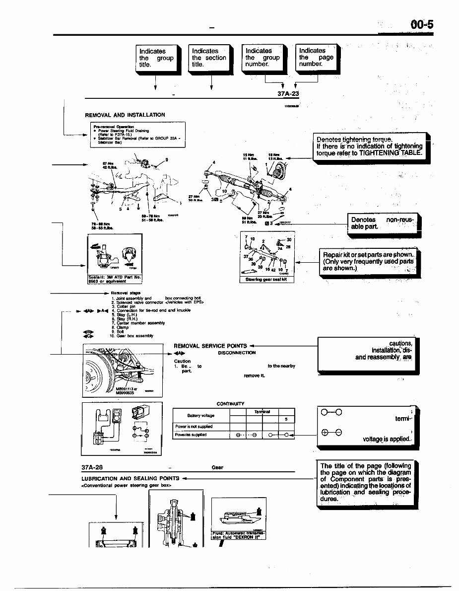
GENERAL - How to Use This Manual 1 STEERING - Power Steering Gear BOX 37A-23 POWER STEERING GEAR BOX REMOVAL AND INSTALLATION 6 A c lmnovel steps 1. Joint assemMy and gear box mnnediw box 2. Sdsnoa vaive con&or <Vehicles ~0th EPS> .I ., I. .~ . REMOVAL SERVICE POINTS 4 4n, TIE-ROD END DISCONNECTKM . Operating procedures, cautions, ’ etc. on removal, instalMtibn:“dis- assembly ‘and rwssembly, qfw 1. Be sun 10 tie the cord of the special tool lo the nearby described. 2. Loosen the nut but do not remove il. \ ” /iv’ FOG LIGHT RELAY CONTlNUfTY CHECK I Tslll7iMl saltwy vob w 0-0 indicates that there is 1 3 4 .5 , continuity’ between the termi- Power is ml suppkl o---a nals. --yr~~~- Power is supplied H indicates terminals‘ to which battery voltagqis applied. \ .) t.canm -. -*.. 37A-28 STEERING - Power Steering Gear Box LUBRICATION AND SEALING POINTS - 4anventlonal power stmlng gear box>
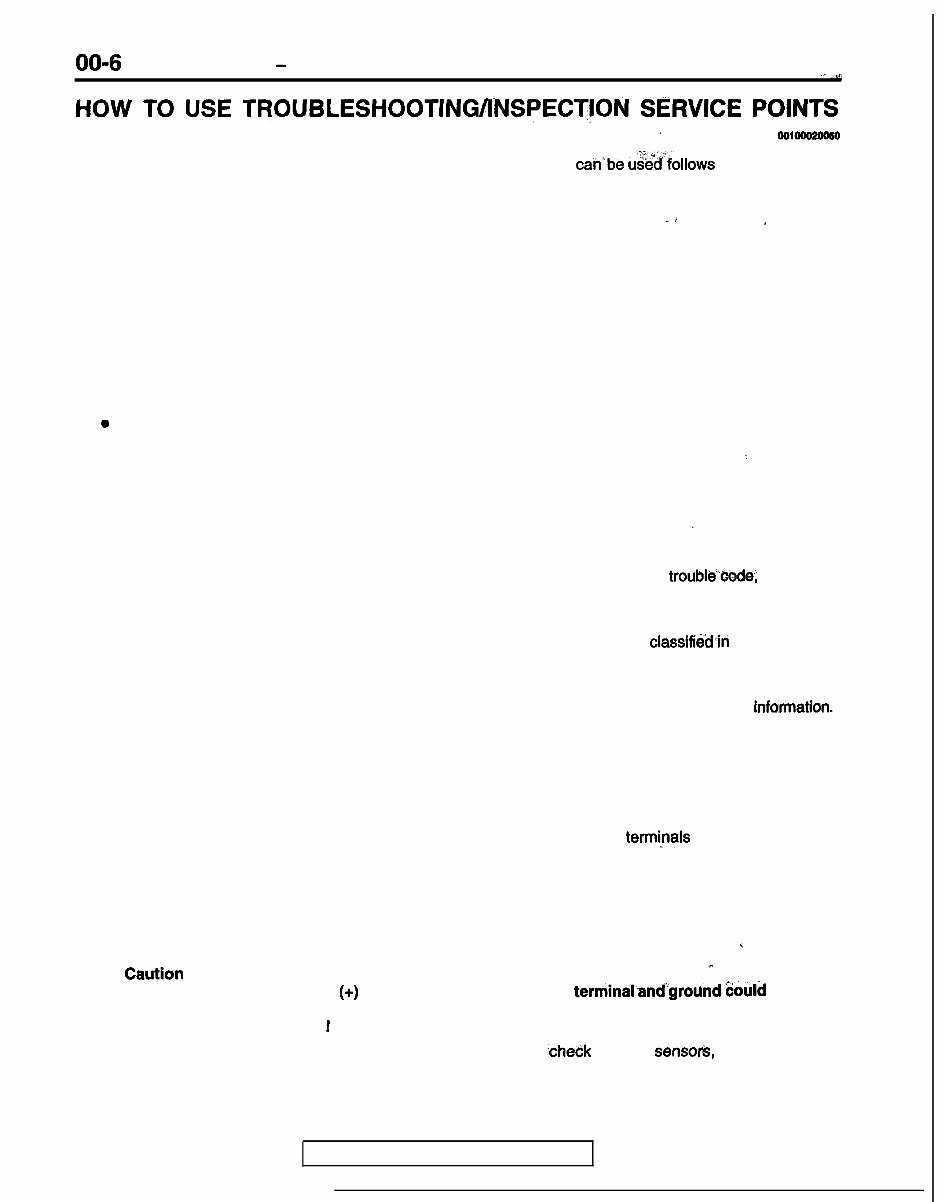
00-6 GENERAL - How to Use Troubleshooting/Inspection Service Points ,(,. _.” * s10w To USE TR~~BLE~H~~TING~~N~PE~T~~~ SERVICE Pomm ‘_ . . oolooo2oo60 Troubleshooting of electronic control systems for which the scan tool can’be u%dfollows the basic outline described below. Furthermore, even in systems for which the scan tool cannot be used, part of these systems still follow this outline. TROUBLESHOOTING CONTENTS ” i 4 1. STANDARD FLOW OF DIAGNOSTIC TROUBLESHOOTING The main procedures for diagnostic troubleshooting are shown. 2. SYSTEM OPERATION AND SYMPTOM VERIFICATION TESTS If verification of the trouble symptoms is difficult, procedures for checking operation and verifying trouble symptoms are shown. 3. DIAGNOSTIC FUNCTION The following diagnostic functions are shown. l , Method of reading diagnostic trouble codes 0 Method of erasing diagnostic trouble codes l Input inspection service points 4. INSPECTION CHART FOR DIAGNOSTIC TROUBLE CODES : 5. INSPECTION PROCEDURE FOR DIAGNOSTIC TROUBLE CODES Indicates the inspection procedures corresponding to each diagnostic trouble code. (Refer to the next page on how to use the inspection procedures.) ,I 6. INSPECTION CHART FOR TROUBLE SYMPTOMS If there are trouble symptoms, even though the scan tool displays no diagnostic trouble”code, inspection procedures for each trouble symptom will be found by means of this chart. 7. INSPECTION PROCEDURE FOR TROUBLE SYMPTOMS Indicates the inspection procedures corresponding to each trouble symptoms classifiedin the Inspection Chart for Trouble Symptoms. (Refer to the next page on how to use the inspection procedures.) 8. DATA LIST REFERENCE TABLE Inspection items and normal judgement values have been provided in this chart as reference infdmation. 9. CHECK AT ECU TERMINALS Terminal numbers for the ECU connectors, inspection items and standard values have been provided in this chart as reference information. Terminal Voltage Checks 1. Connect a needle-nosed wire probe or paper clip to a voltmeter probe. 2. Insert the needle-nosed wire probe into each of the ECU connector termi~nals from the wire side, and measure the voltage while referring to the check chart. NOTE 1. Measure voltage with the ECU connectors connected. 2. You may find it convenient to pull out the ECU to make it easier to reach the connector terminals. 3. Checks don’t have to be carried out in the order given in the chart. I Caution r Short-circuiting the positive (+) probe between a connector terminaland”ground &ould damage the vehicle wiring, the sensor, the ECU, or all three. Use care to prevent this ! 3. If voltage readings differ from Normal Condition values, ,check related sensor&, actuators, and wiring, then replace or repair. TSB Revision
GENERAL - How to Use Troubleshooting/Inspection Service Points 00-7 4. After repair or replacement, recheck -with the voltmeter to confirm @J the repair ,has correbted’ the problem. Terminal Resistance and Continuity Checks 1. Turn the ignition switch to off. 2. Disconnect the ECU connector. 3. Measure the resistance and check for continuity between the terminals of the ECU harnqss-side;, connector while referring to the check chart. 1 NOTE : ? Checks don’t have to be carried out in the order given in the chart. Cautlon ., If resistance and continuity checks are performed dn the wrong terminals, damage t&i46 vehicle wiring, sensors, ECU, and/or ohmmeter may occur. * Use care to prevent this! :. ‘^ /i 4. If the ohmmeter shows any deviation from the Normal Condition value, check the corresponding 5. sensor, actuator and related electrical wiring, then repair or replace. After repair or replacement, recheck with the ohmmeter to confirm that the repair 4es;qq@ed the problem. 1 ‘5. 10. INSPECTION PROCEDURES USING AN OSCILLOSCOPE c When there are inspection procedures using an oscilloscope, these are listed here. :i, ‘; i, ‘.. I, -’ ,I, )” , :, h : !’ I, ‘.l.., ?,” I( ‘, , ,: :. ,‘. .?. I** 1 rc,ASF ,Fi : ‘. ~ TSB Revision I
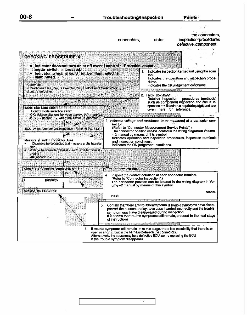
00-8 GENERAL - How to Use Troubleshoo;ting/lnspection Service ~Po;‘k~s’ j I HOW TO USE THE INSPECTION PROCEDURES . : . %\ .j I , The causes of a high frequency of problems occurring in electronic circuitry are generally ;l$ &nec$ors, components, the ECU and the harnesses between connect&s, in that ot-der. These in@ecti&prb&dures follow this order, and they first try to discover a problem with a connector or a defeotive.componfBt. *:. .,.I ) * ~,,“i,’ 1, 1. Indicates insoectiori carried but usink the scan Indicates the opeqtion and inspection proce- du’res. ’ .-‘.‘~, Indicates the OK judgement cuhtfitibn!L 17 Control mode selection switch 2. Thick box lines: Detailed inspection ’ prOCe&r8S ðods) such ‘as component inspection and circuit in- spection are listedon a seplfatb pa@,&nd are given here for reference.., : 3. Indicates voltage and resistance to,” ~~~~~red at a pWic@ar c$ut- nectar. (Refer to “Connector Measurement Service Points”.) The connector position can be located in the wiring diagram in Volume 1 1 -2 manual bv means of this svmbol. Measure bt switch connect - a I 0 Djs --. ‘Of A-44 :onn,ect MB oonnector- and measure at rhe harness side. Indicates opiration and insp&ion prOCedUr8S, inspection terminals and inspection conditions. Indicates the OK judgement conditions. I . Check trouble SymptOm. A h Inspect the contact condition at each connector terminal. (Refer to “Connector Inspection”.) The connector position can be located in the wiring diagram in Vol- ume-2 manual by means of this symbol. I e EOS:ECU. Caution \ \---- After carrying out connector inspection, always be sure to recon- nect the connector as it was before. I I , j ,I: ;, : ,i;J ,, ..;:; ,,.: I:; G&$7, ,‘^& ‘:I,@$ u;q d ,, 5. Confirm that there are troublesymptoms. If trOUbl8SymptOmS havedisap- ,, peared, the connector may have been inserted incorrectly and the trouble symptom may have disappeared during inspection. _’ If it seems that trouble symptoms still remain, proceed to the next stage of instructions. i_ 6. If trouble symptoms still remain up to this stage, there is a possibility that there is an open or short circuit in the harness between the conn8ctors, so check the harness. Alternatively, the cause may be a defective ECU, so try replacing the ECU and check if the trouble symptom disappears. HARNESS INSPECTION Check for an open or short circuit in the harness between the terminals which were defective according to the connector measurements. Carry out this inspection while referring to Volume 2 Electrical manual. Here, “Check harness between power supply and terminal xx” also includes checking for blown fuses. For inspection service points when there is a blown fuse, refer to “Inspection Service Points for a Blown Fuse”. MEASURES TO TAKE AFTER REPLACING THE ECU If the trouble symptoms have not disappeared even after replacing the ECU, repeat the inspection procedure from the beginning. TSB Revision ‘I. ,
The 1997 - 1999 Mitsubishi Eclipse Spyder Service Repair Manual is your ultimate guide to maintaining, repairing, and servicing your Mitsubishi Eclipse Spyder models from 1997 to 1999.
Mitsubishi Eclipse Spyder (1997)
Mitsubishi Eclipse Spyder (1998)
Mitsubishi Eclipse Spyder (1999)
Whether you are a professional technician or a DIY enthusiast, this comprehensive manual provides detailed step-by-step instructions, diagrams, and illustrations to help you tackle any issue with ease.
From routine maintenance tasks like oil changes and filter replacements to complex repairs such as engine overhauls and electrical troubleshooting, this service repair manual has got you covered.
Key features of the 1997 - 1999 Mitsubishi Eclipse Spyder Service Repair Manual:
Complete coverage for all Mitsubishi Eclipse Spyder models from 1997 to 1999
Clear and concise instructions accompanied by detailed diagrams
Comprehensive troubleshooting guides for various systems and components
Detailed procedures for dismantling, repairing, and reassembling each part
Electrical wiring diagrams for easy understanding and troubleshooting
Regular maintenance schedules and recommended service intervals
With the 1997 - 1999 Mitsubishi Eclipse Spyder Service Repair Manual, you can confidently tackle any repair or maintenance task, saving time and money. Get your copy today and keep your Mitsubishi Eclipse Spyder running smoothly!
Recently Viewed
5,521,897Happy Clients
2,594,462eManuals
1,120,453Trusted Sellers
15Years in Business
Price:
Actual Price:
1997 - 1999 Mitsubishi Eclipse Spyder Service Repair Manual