00-1 GROUP 00 GENERAL CONTENTS HOW TO USE THIS MANUAL . . . . . . 00-2 HOW TO USE TROUBLESHOOTING/INSPECTION SERVICE POINTS . . . . . . . . . . . . . . . 00-6 VEHICLE IDENTIFICATION . . . . . . . 00-16 GENERAL DATA AND SPECIFICATIONS . . . . . . . . . . . . . . . 00-20 PRECAUTIONS BEFORE SERVICE. 00-22 SUPPLEMENTAL RESTRAINT SYSTEM (SRS) . . . . . . . . . . . . . . . . . . 00-27 SRS SERVICE PRECAUTIONS . . . . . 00-28 SUPPORT LOCATIONS FOR LIFTING AND JACKING . . . . . . . . . . . . . . . . . . 00-31 STANDARD PART/TIGHTENING- TORQUE TABLE . . . . . . . . . . . . . . . . 00-33
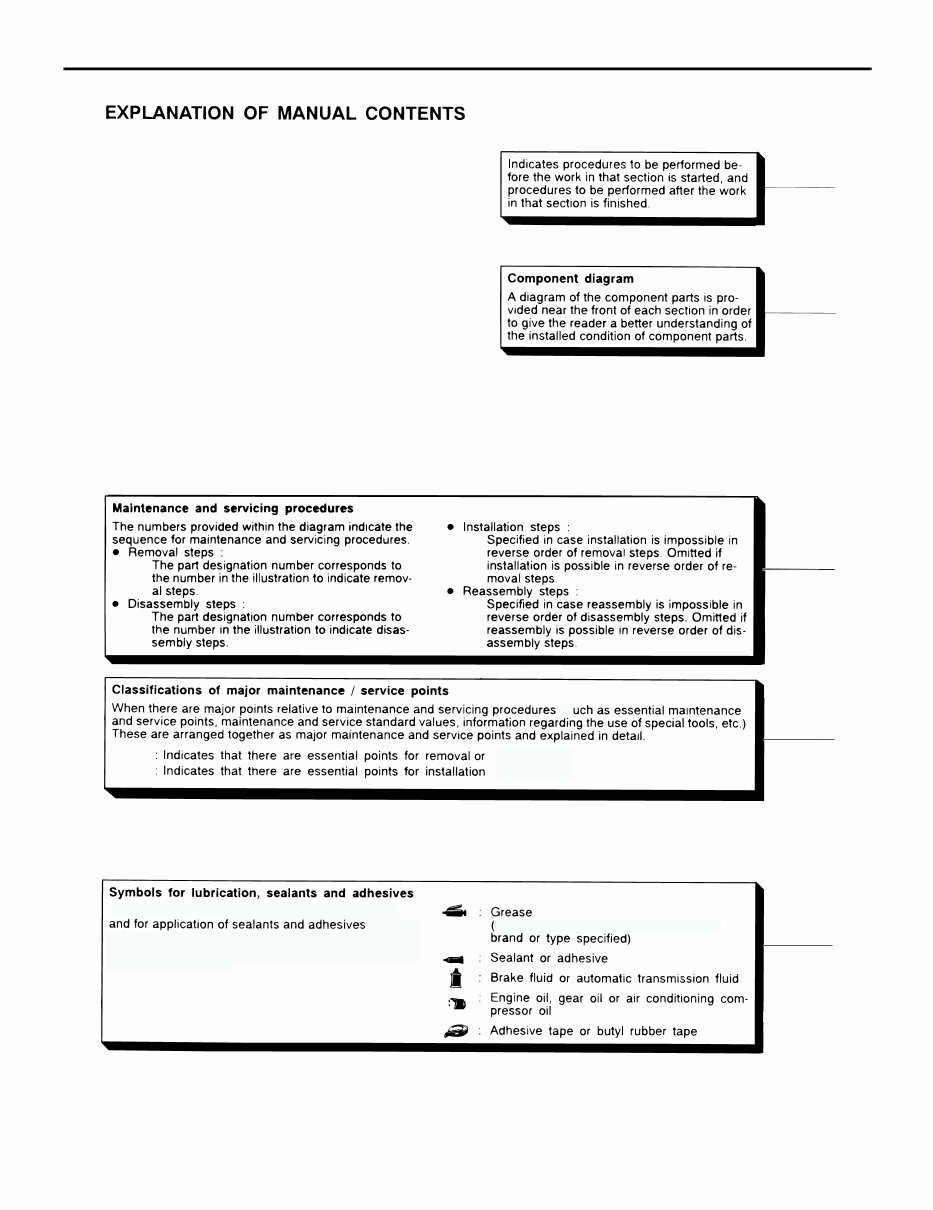
HOW TO USE THIS MANUAL GENERAL 00-2 HOW TO USE THIS MANUAL M1001000100660 SCOPE OF MAINTENANCE, REPAIR AND SERVICING EXPLANATIONS This manual provides explanations, etc. concerning procedures for the inspection, maintenance, repair and servicing of the subject model. Note, however, that for engine and transmission-related component parts, this manual covers only on-vehicle inspections, adjustments, and the removal and installation procedures for major components. For detailed information concerning the inspection, checking, adjustment, disassembly and reassembly of the engine, transmission and major components after they have been removed from the vehicle, please refer to separate manuals covering the engine and the transmission. ON-VEHICLE SERVICE "On-vehicle Service" is procedures for performing inspections and adjustments of particularly important locations with regard to the construction and for maintenance and servicing, but other inspection (for looseness, play, cracking, damage, etc.) must also be performed. INSPECTION Under this title are presented inspection and checking procedures to be performed by using special tools and measuring instruments and by feeling, but, for actual maintenance and servicing procedures, visual inspections should always be performed as well. DEFINITION OF TERMS STANDARD VALUE Indicates the value used as the standard for judging the quality of a part or assembly on inspection or the value to which the part or assembly is corrected and adjusted. It is given by tolerance. LIMIT Shows the standard for judging the quality of a part or assembly on inspection and means the maximum or minimum value within which the part or assembly must be kept functionally or in strength. It is a value established outside the range of standard value. REFERENCE VALUE Indicates the adjustment value prior to starting the work (presented in order to facilitate assembly and adjustment procedures, and so they can be completed in a shorter time). DANGER, WARNING, AND CAUTION DANGER, WARNING, and CAUTION call special attention to a necessary action or to an action that must be avoided. The differences among DANGER, WARNING, and CAUTION are as follows: • If a DANGER is not followed, the result is severe bodily harm or even death. • If a WARNING is not followed, the result could be bodily injury. • If a CAUTION is not followed, the result could be damage to the vehicle, vehicle components or service equipment. INDICATION OF TIGHTENING TORQUE Tightening torques (units: N⋅m) are set to take into account the central value and the allowable tolerance. The central value is the target value, and the allowable tolerance provides the checking range for tightening torques. If bolts and nuts are not provided with tightening torques, refer to P.00-33. MODEL INDICATIONS The following abbreviations are used in this manual for identification of model types. MPI::Indicates the multipoint injection. SOHC::Indicates an engine with the single overhead camshaft. DOHC::Indicates an engine with the double overhead camshaft. 2000:: Indicates models equipped with the 2,000 mL <4G63> petrol engine. 2400::Indicates models equipped with the 2,400 mL <4G69> petrol engine. M/T:: Indicates the manual transmission. A/T:: Indicates the automatic transmission. A/C:: Indicates the air conditioner.
HOW TO USE THIS MANUAL GENERAL 00-3 NOTES
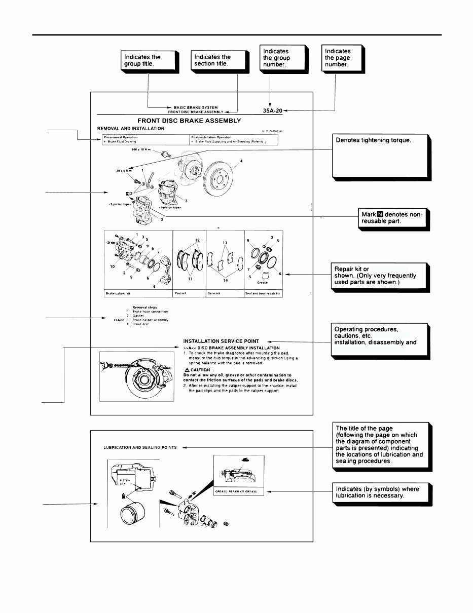
HOW TO USE THIS MANUAL GENERAL 00-4 <<A>> >>A<< (s . disassembly. or reassembly. Symbols are used to show the locations for lubrication . These symbols are included in the diagram of compo- nent parts or on the page following the component parts page. The symbols do not always have accomp- anying text to support that symbol. Multi-purpose grease unless there is a AC301960
HOW TO USE THIS MANUAL GENERAL 00-5 parts sets are On removal, For bolts and nuts which do not have a tightening torque listed, refer to the "Standard Parts tightening-torque Table" reassembly are described AC300860
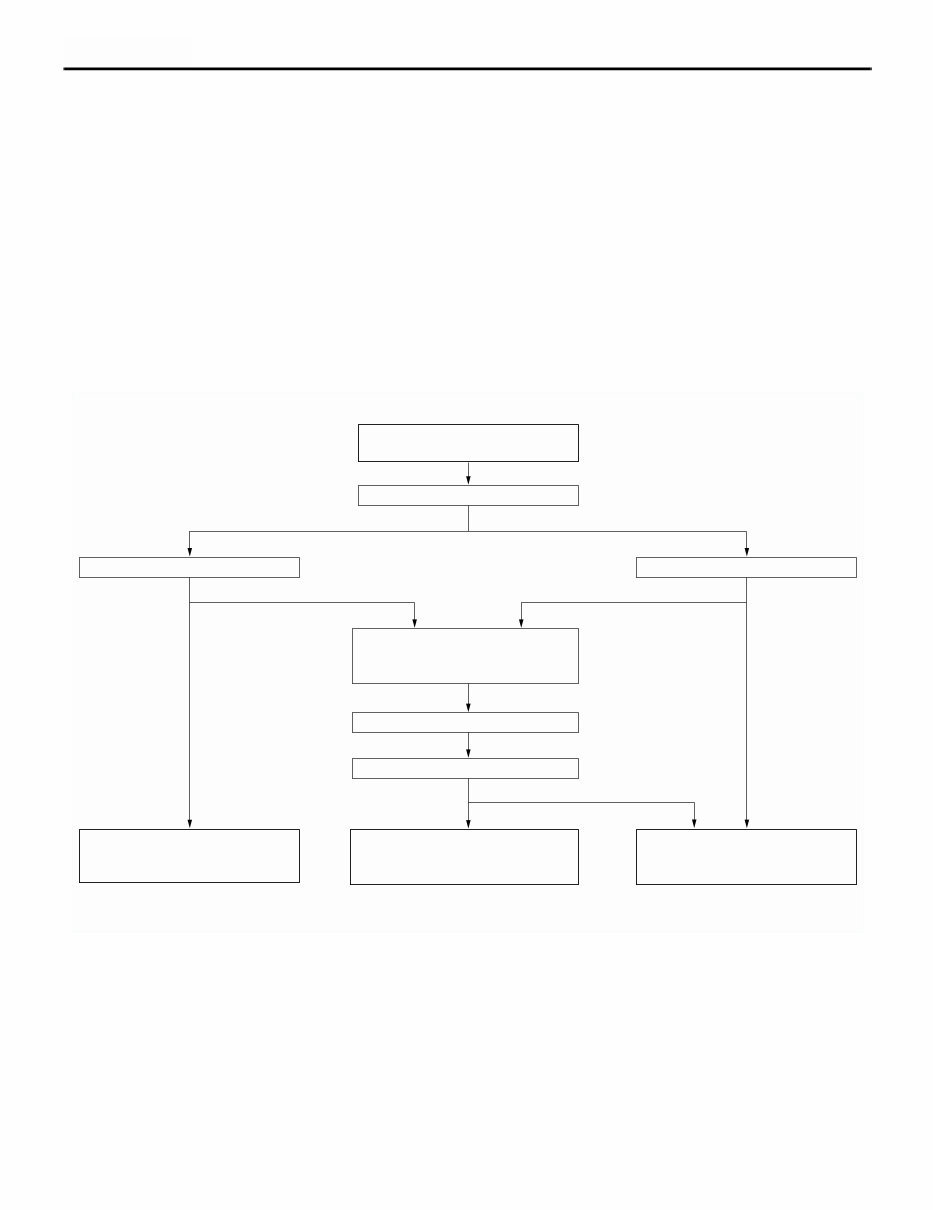
HOW TO USE TROUBLESHOOTING/INSPECTION SERVICE POINTS GENERAL 00-6 HOW TO USE TROUBLESHOOTING/INSPECTION SERVICE POINTS M1001000200582 CONTENTS OF TROUBLESHOOTING Troubleshooting of electronic control systems for which the MUT-II/III can be used follows the basic outline described below. Even in systems for which the MUT-II/III cannot be used, some of these systems still follow this outline. 1. STANDARD FLOW OF DIAGNOSIS TROUBLESHOOTING Troubleshooting sections are based on the diagnostic flow as below. If the diagnostic flow is different from that given below, or if additional explanation is required, the details of such differences or additions will also be listed. Diagnosis method 2. SYSTEM OPERATION AND SYMPTOM VERIFICATION TESTS If verification of the symptom(s) is difficult, procedures for checking operation and verifying symptoms are shown. 3. DIAGNOSIS FUNCTION Details which are different from those in the "Diagnosis function " section are described. 4. DIAGNOSIS CODE CHART Diagnostic trouble codes and diagnostic items are shown. 5. DIAGNOSIS CODE PROCEDURES Indicates the inspection procedures corresponding to each diagnosis code (Refer to How to read inspection procedure ). AC300864AC Gathering information from the customer. Check trouble symptom. Read the diagnosis code. Read the diagnosis code. Refer to the INSPECTION CHART FOR TROUBLE SYMPTOMS (Refer to applicable group.) Refer to the INSPECTION CHART FOR DIAGNOSIS CODES (Refer to applicable group.) INTERMITTENT MALFUNCTIONS After taking note of the malfunction code, erase the diagnosis code memory. Recheck trouble symptom. Read the diagnosis codes. Reoccurs Does not reoccur Diagnosis code displayed. Diagnosis code displayed. Diagnosis code displayed. No diagnosis code or communication with MUT-II/III not possible No diagnosis code. No diagnosis code.
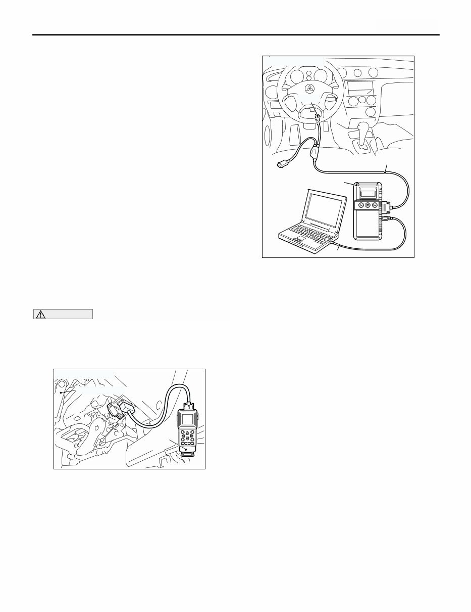
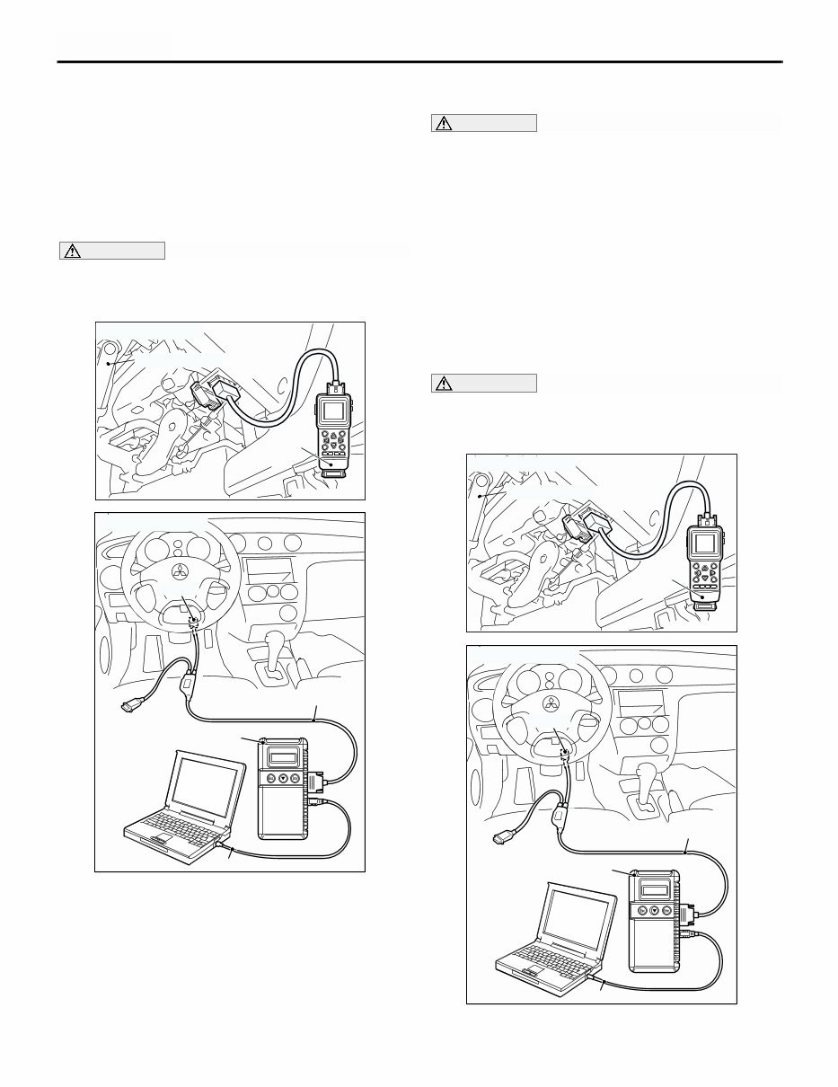
HOW TO USE TROUBLESHOOTING/INSPECTION SERVICE POINTS GENERAL 00-7 6. TROUBLE SYMPTOM CHART If there are trouble symptoms even though the MUT-II/III does not find any diagnosis codes, Inspection procedures for each trouble symptom will be found by means of this chart. 7. SYMPTOM PROCEDURES Indicates the inspection procedures corresponding to each symptoms classified in the Symptom Chart (Refer to How to read inspection procedure P.00-9). 8. SERVICE DATA REFERENCE TABLE Inspection items and normal judgment values have been provided in this chart as reference information. 9. CHECK AT ECU TERMINALS Terminal numbers for the ECU connectors, inspection items, and judgment values have been provided in this chart as reference information. 10. INSPECTION PROCEDURE BY USING AN OSCILLOSCOPE When there are inspection procedures using an oscilloscope, these are described here. DIAGNOSIS FUNCTION HOW TO READ DIAGNOSIS CODE CAUTION Before connecting or disconnecting the MUT-II/III, turn the ignition switch to the "LOCK" (OFF) position. <Using the MUT-II> Connect the MUT-II to the diagnosis connector, and read the diagnosis code. <Using the MUT-III> Connect the MUT-III to the 16-pin diagnosis connector, and read the diagnosis code. NOTE: For details on how to use the MUT-III, refer to the "MUT-III operation manual." 1. Ensure that the ignition switch is at the "LOCK" (OFF). 2. Start up the personal computer. 3. Connect MUT-III USB cable MB991827 to special tool Vehicle Communication Interface (V.C.I.) MB991824 and the personal computer. 4. Connect MUT-III main harness B MB991911 to the V.C.I. 5. Connect MUT-III main harness B to the diagnosis connector. 6. Turn the V.C.I. power switch to the "ON" position. NOTE: When the V.C.I. is energized, the V.C.I. indicator lamp will be illuminated in a green colour. 7. Start the MUT-III system on the PC and turn the ignition switch to the "ON" position. 8. Read the diagnosis code. 9. Disconnecting the MUT-III is the reverse of the connecting sequence, making sure that the ignition switch is at the "LOCK" (OFF). AC300830 Steering shaft MUT-II AC <Using the MUT-II> AC308915 AC MB991911 16-PIN MB991827 MB991824 <Using the MUT-III>
HOW TO USE TROUBLESHOOTING/INSPECTION SERVICE POINTS GENERAL 00-8 NOTE: The ABS warning lamp may flash when the ignition switch is turned ON with the MUT-II/III connected. This is because the diagnosis display function of the ABS warning lamp is activated by grounding the diagnosis connector terminal No.1, and is not detrimental in any way. ERASING DIAGNOSIS CODE (BY USING THE MUT-II/III) CAUTION Before connecting or disconnecting the MUT-II/III, turn the ignition switch to the "LOCK" (OFF) position. Connect the MUT-II/III to the diagnosis connector, and erase the diagnosis code. The procedure is the same as "HOW TO READ DIAGNOSIS CODE ". ERASING DIAGNOSIS CODE (BY USING NO MUT-II/III) CAUTION Some diagnosis codes can not be erased according to the procedure below. If you attempt to erase a diagnosis code, refer to an applicable GROUP. 1. Turn the ignition switch to the "LOCK" (OFF) position. 2. Disconnect the negative battery cable, wait for at least 10 minutes, and then reconnect it. 3. Start the engine and let it run at idle for 10 minutes. INPUT SIGNAL CHECK (WHEN USING THE MUT-II/III) <SWS> CAUTION Before connecting or disconnecting the MUT-II/III, turn the ignition switch to the "LOCK" (OFF) position. AC300830 Steering shaft MUT-II AC <Using the MUT-II> AC308915 AC MB991911 16-PIN MB991827 MB991824 <Using the MUT-III> AC300830 Steering shaft MUT-II AC <Using the MUT-II> AC308915 AC MB991911 16-PIN MB991827 MB991824 <Using the MUT-III>
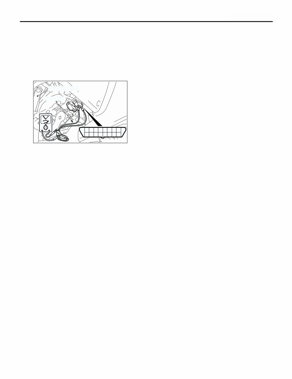
HOW TO USE TROUBLESHOOTING/INSPECTION SERVICE POINTS GENERAL 00-9 1. Connect the MUT-II/III to the diagnosis connector, and erase the diagnosis code. 2. If the MUT-II/III buzzer sounds once when each switch is operated (ON/OFF), the input signal for that switch circuit system is normal. INPUT SIGNAL CHECK (WHEN USING A VOLTMETER) <SWS> 1. Use the special tool diagnosis code check harness (MB991529) to connect the ETACS terminal (terminal 9) and the earth terminals (terminals 4 and 5) of the diagnosis connector to the voltmeter. 2. If the needle of the voltmeter flickers once when each switch is operated (ON/OFF), the input signal for that switch circuit system is normal. HOW TO USE THE INSPECTION PROCEDURES The causes of many of the problems occurring in electric circuitry are generally the connectors, components, the ECU, the wiring harnesses between connectors, in that order. These inspection procedures follow this order. They first try to discover a problem with a connector or a defective component. 12345678 9 10111213141516 AC300831AB Steering shaft MB991529
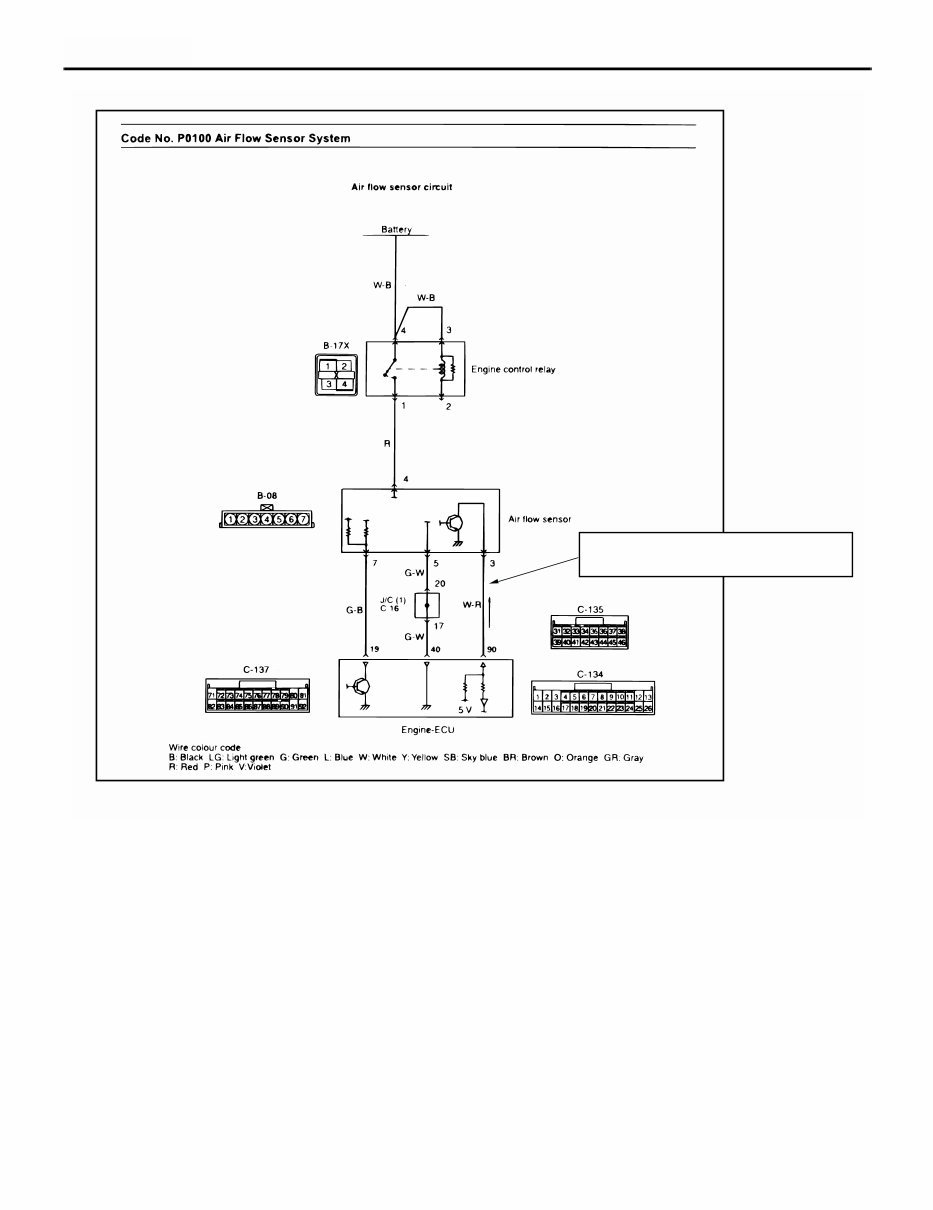
HOW TO USE TROUBLESHOOTING/INSPECTION SERVICE POINTS GENERAL 00-10 AC301964 AB Relevant circuit(s) of the component which the Code No. indicates are described.
You're Reading a Preview
What's Included?
Lifetime Access
Fast Download Speeds
Online & Offline Access
Access PDF Contents & Bookmarks
Full Search Facility
Print one or all pages of your manual
$33.99
2001-2008 Mitsubishi Airtrek Service & Repair Manual
The MITSUBISHI AIRTREK OUTLANDER 2001-2008 Service Repair Manual is a comprehensive guide covering US, Canada, and Europe vehicles. These manuals are widely used by professional mechanics and DIY enthusiasts alike.
Featuring over 5000 pages, this manual provides detailed information on engine overhaul, rebuilding, brakes, sunroof, timing belt replacement, trouble codes, wiring diagrams, troubleshooting, diagnostics, engine performance, front end procedures, suspension, transmission, air conditioning service, computer diagnostic codes, factory maintenance schedules, serpentine belt routings, timing belt service procedures, driving concerns, torque specifications, U-joint and CV-joint service procedures, repair procedures, wiring diagrams, and hundreds of illustrations.
Compatible with both PC and Mac computers, this manual is available in .PDF format for easy viewing and printing. For any issues with downloading, please contact fixyourcar@aol.com for an alternative download link. Please note that the .PDF files can be opened using the included Archive Utility in OS X or Stuffit Expander, which is available for free at http://my.smithmicro.com/mac/stuffit/index.html or http://www.yellowmug.com/yemu/.
Reviews
Q&A
Recently Viewed
5,521,897Happy Clients
2,594,462eManuals
1,120,453Trusted Sellers
15Years in Business
Price:
Actual Price:
2001-2008 Mitsubishi Airtrek Service & Repair Manual





 Lifetime Access




