Maintenance schedule 1•3 1 Every 250 miles (400 km) or weekly m Refer to “Weekly Checks” Every 3000 miles (5000 km) or 3 months, whichever comes first In addition to the items listed above, carry out the following: m Adjust the front and rear drum brakes (Section 3) m Check the operation of the handbrake and adjust if necessary (Section 4) m Check the condition and security of the steering and suspension components (Section 5) m Inspect the underbody and the brake hydraulic pipes and hoses (Section 6) m Check the condition of the fuel lines (Section 6) m Check the condition and security of the exhaust system (Section 7) m Check the condition of the fan belt and renew if necessary (Section 8) m Check the condition of the air pump drivebelt (where applicable) and renew if necessary (Section 9) m Inspect the clutch hydraulic components (Section 10) m Check the condition of the seats and seat belts (Section 11) m Check the headlight beam alignment (Section 12) Every 6000 miles (10 000 km) or 6 months, whichever comes first In addition to the items listed above, carry out the following: m Renew the engine/transmission oil and filter (Section 13) m Check the condition of the front brake shoes and/or pads, and renew if necessary (Section 14) m Check the condition of the driveshaft gaiters (Section 15) m Lubricate the suspension and steering grease points (Section 16) m Check the condition of the rear brake shoes and renew if necessary (Section 17) m Check all underbonnet components and hoses for fluid leaks (Section 18) m Check and if necessary top up the carburettor piston dashpot and lubricate the linkage (Section 19) Every 6000 miles (10 000 km) or 6 months, whichever comes first (continued) m Check the condition of the contact breaker points and adjust or renew (Section 20) m Lubricate the distributor (Section 21) m Check and if necessary adjust the clutch return stop (Section 22) m Lubricate the dynamo bearing - early models (Section 23) m Clean and inspect the dynamo charging system control box (Section 24) m Check and if necessary adjust the ignition timing (Section 25) m Check and if necessary adjust the carburettor idle speed and mixture settings (Section 26) m Lubricate the locks and hinges (Section 27) m Check the condition of the exterior trim and paintwork (Section 28) m Road test (Section 29) Note: Renewal of the engine/transmission oil and filter at this service interval is only necessary on pre-1985 models. On all other models, oil and filter renewal is recommended at 12 000 miles/12 months. Every 12 000 miles (20 000 km) or 12 months, whichever comes first In addition to the items listed above, carry out the following: m Renew the air cleaner element (Section 30) m Check and if necessary adjust the valve clearances (Section 31) m Inspect the distributor cap, rotor arm and HT leads (Section 32) m Renew the spark plugs (Section 33) m Check the emission control equipment (Section 34) Every 24 000 miles (40 000 km) or twenty four months, whichever comes first In addition to the items listed above, carry out the following: m Renew the coolant (Section 35) m Renew the brake fluid (Section 36) m Renew the fuel filter - fuel injection models (Section 37) The maintenance intervals in this manual are provided with the assumption that you, not the dealer, will be carrying out the work. These are the average maintenance intervals recommended by the manufacturer for vehicles driven daily under normal conditions. Obviously some variation of these intervals may be expected depending on territory of use, and conditions encountered. If you wish to keep your vehicle in peak condition at all times, you may wish to perform some of these procedures more often. We encourage frequent maintenance because it enhances the efficiency, performance and resale value of your vehicle. If the vehicle is driven in dusty areas, used to tow a trailer, driven frequently at slow speeds (idling in traffic) or on short journeys, more frequent maintenance intervals are recommended.
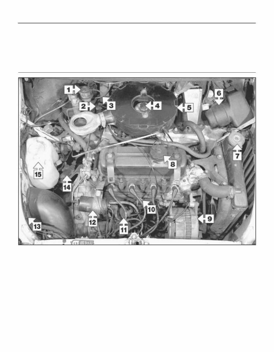
1•4 Maintenance - component location Underbonnet view of a 998 cc Mini 1000 Saloon 1 Brake master cylinder reservoir 2 Clutch master cylinder reservoir 3 Fuse block 4 Carburettor piston damper 5 Air cleaner 6 Windscreen wiper motor 7 Radiator pressure cap 8 Engine/transmission oil filler cap 9 Alternator 10 Engine/transmission oil dipstick 11 Distributor 12 Ignition coil 13 Vehicle identification plate 14 Clutch slave cylinder 15 Windscreen washer reservoir
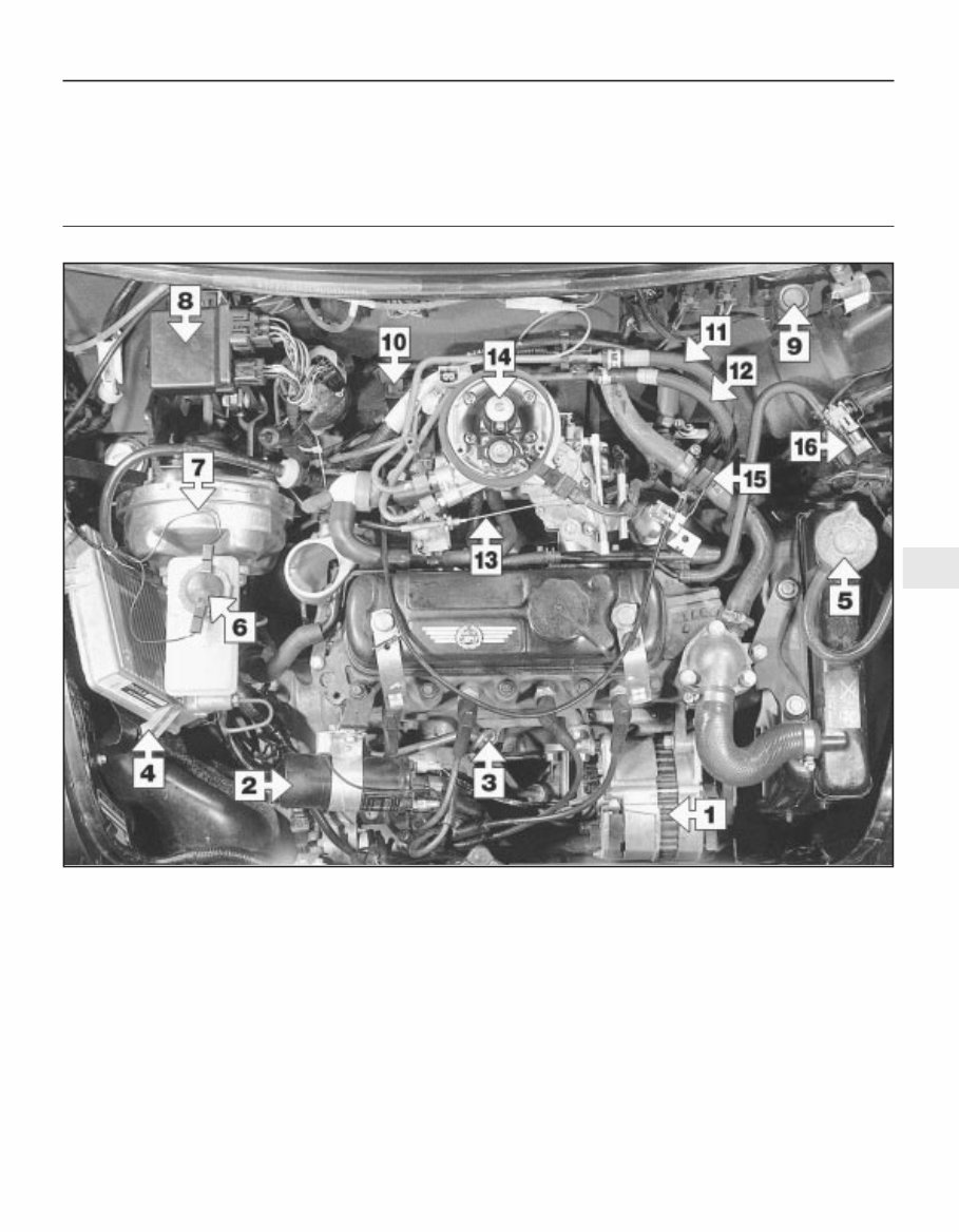
Maintenance - component location 1•5 1 Underbonnet view of a 1275 cc Mini Cooper Saloon (air cleaner removed for clarity) 1 Alternator 2 Ignition coil 3 Engine/transmission oil dipstick 4 Engine management (fuel injection/ignition) ECU 5 Radiator pressure cap 6 Brake fluid reservoir cap 7 Brake system vacuum servo unit 8 Relay module 9 Fuel cut-off inertia switch 10 Manifold absolute pressure (MAP) sensor fuel trap 11 Fuel return pipe 12 Fuel feed pipe 13 Accelerator cable 14 Throttle body assembly 15 Heater coolant valve 16 Charcoal canister purge valve
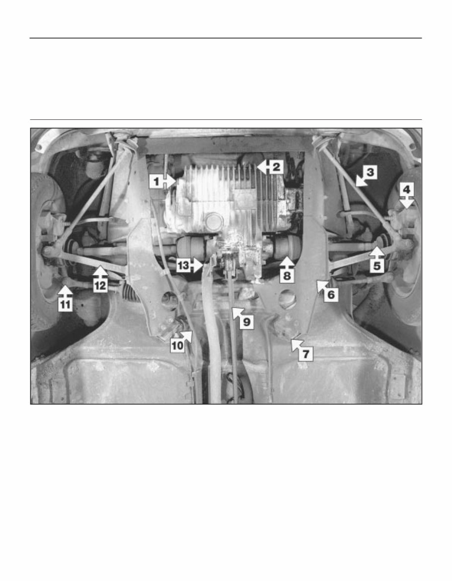
1•6 Maintenance - component location Front underside view of a 998 cc Mini 1000 Saloon 1 Engine/transmission oil drain plug 2 Oil filter 3 Front suspension tie-bar 4 Disc brake caliper 5 Driveshaft outer CV joint 6 Front subframe 7 Subframe rear mounting 8 Offset sphere type inner CV joint 9 Gearchange extension rod 10 Battery positive cable 11 Steering tie-rod outer balljoint 12 Lower suspension arm 13 Exhaust bracket
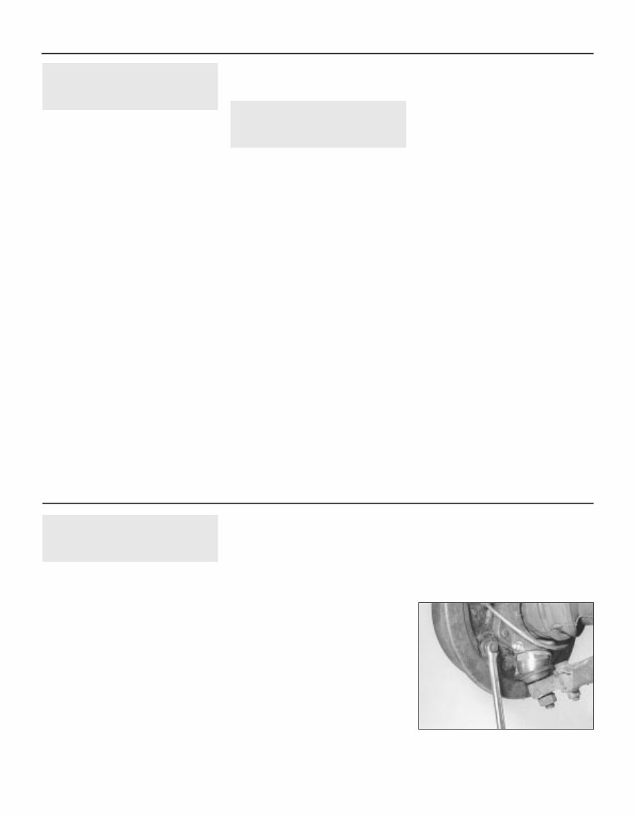
1 Introduction 1 This Chapter is designed to help the home mechanic maintain his/her vehicle for safety, economy, long life and peak performance. 2 This Chapter contains a master maintenance schedule, followed by Sections dealing specifically with each task in the schedule. Visual checks, adjustments, component renewal and other helpful items are included. Refer to the accompanying illustrations of the engine compartment and the underside of the vehicle for the locations of the various components. 3 Servicing your vehicle in accordance with the mileage/time maintenance schedule and the following Sections will provide a planned maintenance programme, which should result in a long and reliable service life. This is a comprehensive plan, so maintaining some items but not others at the specified service intervals will not produce the same results. 4 As you service your vehicle, you will discover that many of the procedures can - and should - be grouped together, because of the particular procedure being performed, or because of the close proximity of two otherwise-unrelated components to one another. For example, if the vehicle is raised for any reason, the exhaust should be inspected at the same time as the suspension and steering components. 5 The first step of this maintenance programme is to prepare yourself before the actual work begins. Read through all the Sections relevant to the work to be carried out, then make a list and gather together all the parts and tools required. If a problem is encountered, seek advice from a parts specialist or a dealer service department. 2 Intensive maintenance 1 If, from the time the vehicle is new, the routine maintenance schedule is followed closely, and frequent checks are made of fluid levels and high-wear items, as suggested throughout this manual, the engine will be kept in relatively good running condition, and the need for additional work will be minimised. 2 It is possible that there will be some times when the engine is running poorly due to the lack of regular maintenance. This is even more likely if a used vehicle, which has not received regular and frequent maintenance checks, is purchased. In such cases, additional work may need to be carried out, outside of the regular maintenance intervals. 3 If engine wear is suspected, a compression test (refer to Chapter 2A) will provide valuable information regarding the overall performance of the main internal components. Such a test can be used as a basis to decide on the extent of the work to be carried out. If, for example, a compression test indicates serious internal engine wear, conventional maintenance as described in this Chapter will not greatly improve the performance of the engine, and may prove a waste of time and money, unless extensive overhaul work (Chapter 2B) is carried out first. 4 The following series of operations are those often required to improve the performance of a generally poor-running engine: Primary operations a) Clean, inspect and test the battery (See “Weekly checks”). b) Check all the engine-related fluids (See “Weekly checks”). c) Check and if necessary adjust the valve clearances (Section 31). d) Check the condition of the fan belt (Section 8). e) Top up the carburettor piston damper (Section 19) f) Check the condition and adjustment of the contact breaker points (Section 20). g) Inspect the distributor cap, rotor arm and HT leads (Section 32). h) Renew the spark plugs (Section 33). i) Check and if necessary adjust the ignition timing (Section 25). j) Check the condition of the air cleaner filter element and renew if necessary (Section 30). k) Check and if necessary adjust the carburettor idle speed and mixture settings (Section 26). l) Renew the fuel filter - fuel injection models (Section 37). m) Check the condition of all hoses, and check for fluid leaks (Section 18). 5 If the above operations do not prove fully effective, carry out the following operations: Secondary operations All the items listed under “Primary operations”, plus the following: a) Check the charging system (Chapter 5A). b) Check the ignition system (Chapter 5B). c) Check the fuel system (Chapter 4A and B). d) Renew the distributor cap and rotor arm (Section 32). e) Renew the ignition HT leads (Section 32). 3 Drum brake adjustment 2 1 As wear takes place on the brake shoe friction material, the clearance between the friction material and the inner circumference of the brake drum will increase, resulting in excessive brake pedal travel before the brakes are applied. To compensate for this, adjusters are provided at the rear of each brake backplate, enabling the clearance between the brake shoe and drum to be kept to a minimum. 2 At the front two adjusters are fitted to each brake backplate. At the rear a single adjuster is located at the top of each brake backplate. Front brakes 3 Chock the rear wheels then jack up the front of the car and support it on axle stands (see “Jacking and vehicle support”). 4 Each front brake has two adjusters of the eccentric cam type, accessible from the rear of each brake backplate. One of these adjusters is located behind the steering arm and insufficient clearance exists to enable an ordinary brake adjusting spanner to be used. Providing the adjuster is not excessively tight or partially seized in the backplate, a 5 / 16 in AF open-ended spanner can be used quite successfully to turn the adjuster. 5 Begin by turning one of the adjusters in the forward direction of wheel rotation until the wheel is locked (see illustration). Now back it off slightly, until the wheel turns freely. The brake drum may rub slightly in one or two places as the wheel is turned. This is acceptable providing the wheel does not bind. Caution: If, when attempting to adjust the brakes, the square-headed adjuster is reluctant to turn, it is quite likely that it has become seized in its housing. If this is the case do not force it, or you will probably break off the square head, necessitating renewal of the complete backplate assembly. Apply liberal amounts of penetrating oil to the rear of the adjuster and allow it to soak in. Now turn the adjuster back and forth slightly, using gentle force if necessary, increasing the movement each time. When the adjuster turns easily apply a multipurpose grease to 1•8 Maintenance procedures Every 3000 miles or 3 months 3.5 Adjusting one of the front brake adjusters with a brake adjusting spanner
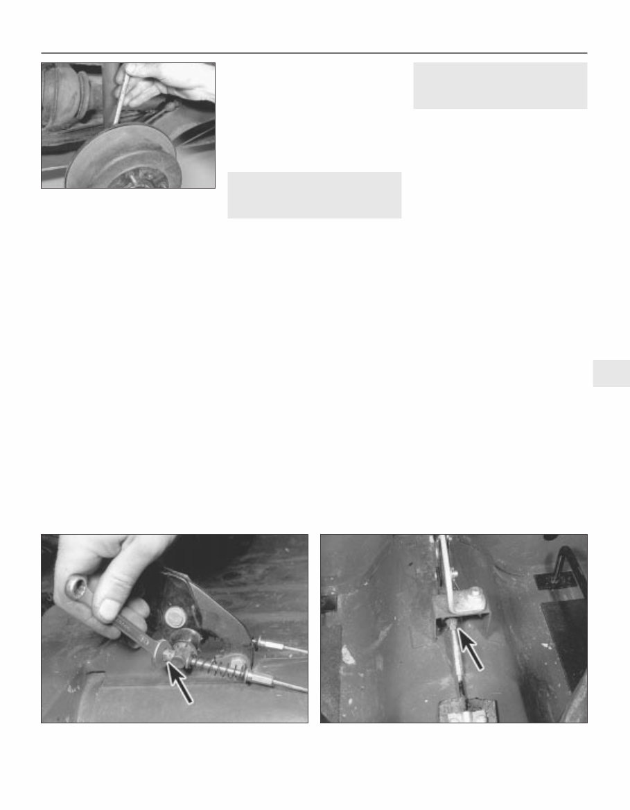
the exposed portion of the adjuster at the rear of the backplate and then turn it through its entire travel. Preferably do this with the brake drum removed. 6 Turn the second adjuster also in the direction of forward wheel rotation until the drum locks again. Now back the adjuster off until the wheel turns freely once more. 7 Repeat this procedure for the other front wheel and then lower the car to the ground. Rear brakes 8 Chock the front wheels then jack up the rear of the car and support it on axle stands (see “Jacking and vehicle support”). Ensure that the handbrake is off. 9 Using a brake adjusting spanner, turn the square-headed adjuster in a clockwise direction (viewed from the rear of the backplate) until the wheel is locked (see illustration). The adjusters on the rear brakes are even more prone to seizure than those at the front. If the adjuster is reluctant to turn attempt to free it off as described above. If this fails, remove the rear brake drums and brake shoes as described in Chapter 9, and clean and lubricate the adjuster thoroughly. When all is well, refit the brake assemblies and start the adjustment procedure again. 10 Now turn the adjuster back a quarter of a turn at a time until the wheel turns freely without binding. A slight rubbing may be felt when the wheel is turned slowly, indicating a high spot on the drum or dust on the linings. This is acceptable providing the drum does not bind. 11 Repeat this procedure for the other rear brake then, before lowering the car to the ground, check the handbrake adjustment as described in the following Section. 4 Handbrake check and adjustment 2 1 Adjustment of the handbrake cables is usually only necessary after high mileage when a slight stretching of the cables will have taken place, or if the cables have been removed. 2 Before adjusting the handbrake check that the footbrake is correctly adjusted as described in Section 3. 3 Chock the front wheels then jack up the rear of the car and support it on axle stands (see “Jacking and vehicle support”). 4 Apply the handbrake lever to the third notch of the ratchet and check that the rear wheels are locked. If not, adjust the handbrake as follows. 5 With the handbrake still applied to the third click of the ratchet, tilt the front seats forward, and on models having twin cables, tighten the cable adjusting nuts at the base of the lever until the rear wheels can only just be turned by heavy hand pressure. On models having a single front cable, slacken the locknut and rotate the cable adjusting nut. When the wheels can only just be turned by heavy hand pressure, tighten the locknut (see illustrations). 6 Release the handbrake lever and ensure that the wheels rotate freely. If satisfactory lower the car to the ground. 5 Steering and suspension check 2 Steering 1 First check for wear in the steering tie-rod outer balljoints. Turn the steering to left or right lock sufficiently to allow the joints to be observed. Now have an assistant turn the steering wheel back and forth slightly. If there is any side movement in the balljoint it must be renewed. Similarly place your hand over the rubber gaiter at the end of the rack housing and feel for any excess free play of the inner balljoint. If the condition of this joint is suspect, a further investigation should be carried out with the gaiter removed as described in Chapter 10. 2 Check the tightness of the steering column clamp bolt at the base of the column. Any slackness at this joint can also show up as free play at the steering wheel. Front suspension 3 To inspect the front suspension, chock the rear wheels then jack up the front of the car and support it on axle stands (see “Jacking and vehicle support”). 4 Visually inspect the balljoint dust covers and the steering gear gaiters for splits, chafing or deterioration. Any wear of these components will cause loss of lubricant, together with dirt and water entry, resulting in rapid deterioration of the balljoints or steering gear. 5 Grasp the roadwheel at the 12 o’clock and 6 o’clock positions and try to rock it. If any movement is felt it is likely to be in one or more of the following areas: Hub bearings 6 Continue rocking the wheel while your assistant depresses the footbrake. If the Every 3000 miles or 3 months 1•9 1 3.9 Adjusting the rear brakes 4.5a Handbrake adjustment on models with twin cables 4.5b Handbrake cable adjusting nut on models with a single front cable
This MINI COOPER SERVICE REPAIR MANUAL is a comprehensive guide suitable for individuals interested in the technical aspects of this brand. It provides immediate access to a wealth of technical details sourced directly from the manufacturer.
Whether you are a professional mechanic or a DIY enthusiast, this manual offers complete information on maintenance and repairs for any MINI COOPER model. Our team of skilled mechanics has contributed their expertise to ensure that you receive quality information, including various equipment and diagrams.
With a focus on delivering high-quality solutions, this car service manual encompasses mechanical and technical specifications, introductory mechanics, equipment elevation, collision details, products and supplies, as well as painting and descriptions of various vehicle parts.
By accessing this manual, you gain step-by-step instructions, accompanied by illustrations, for assembly, disassembly, cleaning, repairing, and maintenance of MINI COOPER vehicles.
Embracing the digital age, this manual allows you to access the information instantly without the need for printed books or postage. Take advantage of the opportunity to access this valuable resource with just one click and commence your repairs or maintenance without delay.