

1996 Mercury Cougar Service & Repair Manual Software
What's Included?
Fast Download Speeds
Offline Viewing
Access Contents & Bookmarks
Full Search Facility
Print one or all pages of your manual

E - THEORY/OPERATION - 4.6L
1996 ENGINE PERFORMANCE Ford Motor Co. - Theory & Operation - EEC-V
INTRODUCTION
This article covers basic description and operation of engine performance-related systems and components.
Read this article before diagnosing vehicles or systems with which you are not completely familiar.
COMPUTERIZED ENGINE CONTROLS
CONTROLS
Powertrain Control Module (PCM)
PCM monitors engine operating conditions by input received from engine sensors. Control of output actuators
determines fuel mixture and idle speed. PCM is located behind right kick panel.
The engine control system consists of the PCM, relays, modules, sensors, switches and actuators. The PCM
sends out electrical reference signals to engine sensors and then analyzes the return signals. The engine sensors
supply the PCM with specific information, in the form of electrical signals, to determine engine operating
conditions.
In the event of a sensor or actuator failure, the PCM initiates an alternative strategy called Failure Mode Effects
Management (FMEM) to allow the vehicle to maintain driveability. In the event of PCM failure, Hardware
Limited Operation Strategy (HLOS) will be activated. HLOS is a system of alternate circuitry that provides
minimal engine operation if the PCM fails. During HLOS, all self-test function will stop and system will be
controlled by electronic hardware.
Malfunction Indicator Light (MIL) will remain on whenever FMEM or HLOS is in operation. FMEM and
HLOS substitute a fixed signal and continue to monitor system failure. If signal(s) return to within operating
limits, PCM will resume normal operation.
Constant Control Relay Module (CCRM)
CCRM interfaces with the PCM to control cooling fan, A/C clutch and fuel pump operation. The CCRM also
incorporates electronic engine control power relay to supply power to the EEC-V system.
Fuel Pump Driver Module (FPDM)
FPDM interfaces with the PCM to control fuel pump operation. By controlling fuel pump operation, noise and
the amount of hot fuel returned to the fuel tank is minimized. If FPDM or system fail self-test, DTC P1230,
P1233, P1234, P1235 P1236, P1237 or P1238 may be set in PCM memory.
NOTE: Components are grouped into 2 categories. The first category covers INPUT
DEVICES, which control or produce voltage signals monitored by the control
unit. The second category covers OUTPUT SIGNALS , covering components
controlled by the PCM.
1996 Ford Thunderbird LX
E - THEORY/OPERATION - 4.6L 1996 ENGINE PERFORMANCE Ford Motor Co. - Theory & Operation - EEC-V
1996 Ford Thunderbird LX
E - THEORY/OPERATION - 4.6L 1996 ENGINE PERFORMANCE Ford Motor Co. - Theory & Operation - EEC-V

INPUT DEVICES
Vehicles are equipped with different combinations of input devices. Not all devices are used on all models. To
determine the input device used on a specific model, see wiring diagram in the WIRING DIAGRAMS article.
The available input signals include the following:
Brake On/Off (BOO) Switch
BOO switch is wired to brakelight circuit. It signals the PCM when the brake is applied. The BOO input is used
to adjust engine idle when A/C is in use and to control torque converter clutch lock/unlock strategy.
Camshaft Position (CMP) Sensor
EEC-V uses 2 types of CMP sensors. A variable reluctance sensor is used.
CMP sensor is used to determine the position of the camshaft and to identify when piston No. 1 is at TDC of
compression stroke. CMP sensor provides cylinder identification information during engine start-up for PCM to
initiate correct firing order. Cylinder identification information signal is sent from CMP sensor to PCM through
CID circuit.
Clutch Pedal Position (CPP) Switch
CPP switch is mounted near clutch pedal. CPP indicates clutch pedal position by means of an on/off switch
signal. This signal is used by PCM to determine clutch pedal position and on some models, gear shift selector
position.
Coolant Temperature Sensor
See ENGINE COOLANT TEMPERATURE (ECT) SENSOR (Below).
Crankshaft Position (CKP) Sensor
CKP sensor is a Hall Effect magnetic switch. The Hall Effect switch is activated by vanes on the crankshaft
damper and pulley assembly. The Profile Ignition Pick-Up (PIP) is a crankshaft position signal that is sent to the
PCM. The PIP signal generated by the Hall Effect sensor provides base timing and RPM information to the
PCM.
Cylinder Head Temperature (CHT) Sensor
CHT sensor is the input signal used for the cooling system failsafe strategy. CHT sensor signals PCM to
activate failsafe strategy if cylinder head temperature exceeds pre-programmed conditions. If CHT sensor or
system fail self-test, DTC P1288, P1289, P1290 or P1299 may set in PCM memory.
Data Link Connector (DLC)
The 16-pin Data Link Connector (DLC) is used to perform the Quick Test diagnostic procedure. When scan tool
connected to DLC, fault code output function can be activated.
Differential Pressure Feedback EGR (DPFE) Sensor
1996 Ford Thunderbird LX
E - THEORY/OPERATION - 4.6L 1996 ENGINE PERFORMANCE Ford Motor Co. - Theory & Operation - EEC-V

See EGR SYSTEM under EMISSION SYSTEMS.
Electronic Vacuum Regulator (EVR) Solenoid
See EGR SYSTEM under EMISSION SYSTEMS.
Engine Coolant Temperature (ECT) Sensor
ECT sensor is a thermistor device which changes resistance proportionate to temperature changes. ECT sensor
inputs coolant temperature to the PCM. ECT sensor is threaded into heater outlet fitting or coolant passage.
Engine RPM/Vehicle Speed Limiter System
The engine RPM/vehicle speed limiter system is integrated into PCM. The purpose of this system is to prevent
damage to the powertrain in overspeed conditions.
Whenever engine RPM or vehicle speed is detected, PCM will disable some or all of the fuel injectors. This will
cause engine to run rough and DTC P1270 will set in PCM memory. When overspeed condition has been
discontinued, normal engine operating conditions will be restored.
Fan Monitor (FANM)
FANM circuit is spliced into the Power-To-Low Speed Fan circuit. PCM monitors FANM circuit for diagnostic
purposes. When cooling fan(s) is off, FANM circuit voltage is pulled low by path to ground through cooling
fan.
With FANM circuit voltage low, PCM can verify FANM circuit and Power-To-Low Speed Fan circuit are
complete from FANM splice through cooling fan to ground. This also confirms that circuits are not shorted to
power.
When fan is on, voltage is supplied from CCRM to the appropriate Power-To-Fan and FANM circuit. With
cooling fan on and FANM circuit high, PCM can verify fan control relay contacts in the CCRM are closed and
that battery voltage is being supplied to the CCRM for the LFC and HFC relays. See CCRM circuit schematic
in CIRCUIT TEST X in the TESTS W/CODES article for more information.
Fuel Pump Monitor (FPM)
FPM circuit is spliced into the Power-To-Pump circuit and used by the PCM for diagnostic purposes. The PCM
sources a low current voltage down the FPM circuit.
With the fuel pump off, voltage is pulled low by the path to ground through the fuel pump. With the fuel pump
off and the FPM circuit low, the PCM can verify that FPM and, circuit and Power-To-Pump circuit are
complete from the FPM splice through the fuel pump to ground.
With the fuel pump on, voltage is supplied from the CCRM to the Power-To-Pump and FPM circuits. With the
fuel pump on and FPM circuit high, PCM can verify that Power-To-Pump circuit from CCRM to FPM splice is
complete. It can also verify that fuel pump relay contacts are closed and battery voltage is supplied to CCRM
for the relay. See CCRM circuit schematic in CIRCUIT TEST X in the TESTS W/CODES article for more
1996 Ford Thunderbird LX
E - THEORY/OPERATION - 4.6L 1996 ENGINE PERFORMANCE Ford Motor Co. - Theory & Operation - EEC-V
information.
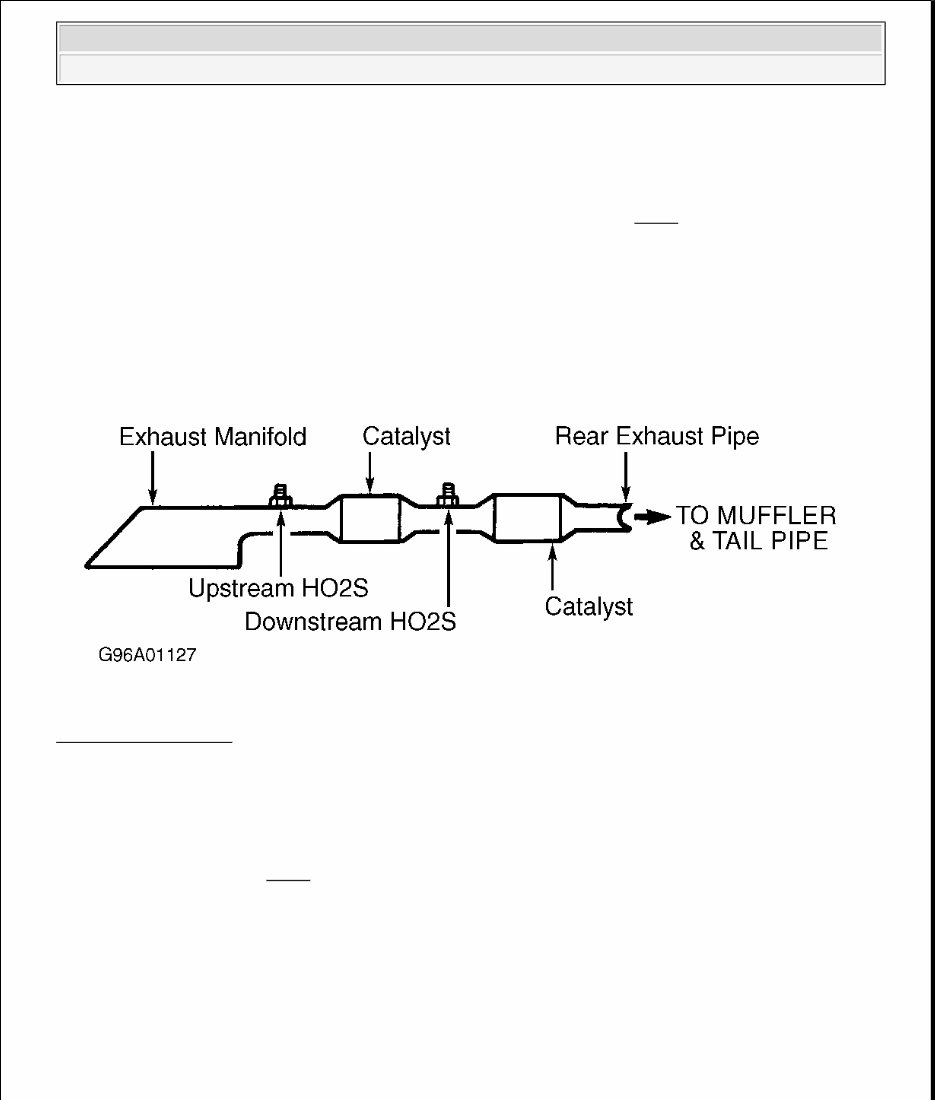
Heated Oxygen Sensor (HO2S)
The heated oxygen sensors are mounted in the exhaust manifold and pipe. See Fig. 1 . HO2S sensor uses a
built-in heating circuit. The heating circuit is used to bring the HO2S sensor up to operating temperature,
enabling faster conversion to closed-loop operation.
HO2S monitors oxygen content of exhaust gases. When HO2S is at operating temperature, a voltage signal is
produced, which varies according to oxygen content of exhaust gases. Signal is transmitted to the PCM and is
translated into a rich or lean mixture signal.
Fig. 1: Locating HO2S
Courtesy of FORD MOTOR CO.
Mass Airflow (MAF) Sensor
MAF sensor uses a hot wire sensing element to measure amount of air entering the engine. Air passing over the
hot wire causes it to cool. The hot wire is maintained at 392°F (200°C) above ambient temperature, as measure
by a constant cold wire. See Fig. 2 .
The current required to maintain hot wire operating temperature is proportional to the intake air mass. The PCM
calculates the fuel injector pulse width in order to provide the desired air/fuel ratio.
1996 Ford Thunderbird LX
E - THEORY/OPERATION - 4.6L 1996 ENGINE PERFORMANCE Ford Motor Co. - Theory & Operation - EEC-V
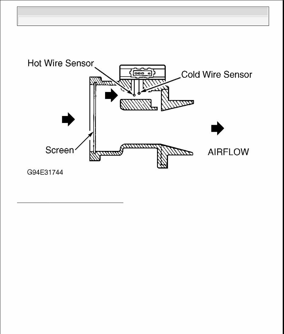
Fig. 2: Cross - Sectional View Of MAF Sensor
Courtesy of FORD MOTOR CO.
Octane Adjust Shorting Bar
The octane adjust shorting bar is used to retard spark. A diagnostic trouble code will set if Octane Adjust
Shorting Bar is removed or, if an open circuit is present.
Output Shaft Speed (OSS) Sensor
The OSS sensor is a magnetic pick-up that sends a voltage signal to the PCM. This signal tells the PCM
transmission output shaft speed. Voltage is also used for shift schedules, modulated converter clutch control,
and determining EPC pressure.
OSS sensor is located on the rear of transmission case, on driver's side of vehicle. Control functions associated
with OSS sensor are limiting vehicle speed, converter clutch control and shift quality.
Park/Neutral Position (PNP) Switch
PNP switch is mounted on transmission selector lever. PNP indicates shift lever position by means of a variable
resistance signal. This signal is used by PCM to determine gear shift selector position.
Throttle Position (TP) Sensor
1996 Ford Thunderbird LX
E - THEORY/OPERATION - 4.6L 1996 ENGINE PERFORMANCE Ford Motor Co. - Theory & Operation - EEC-V

TP sensor is a rotary potentiometer. TP sensor monitors throttle plate opening. Its signal to the PCM is
proportional to throttle plate opening angle and rate of angle change. The TP sensor signal affects air/fuel ratio,
injector timing, idle speed, EGR flow and ignition timing. The TP sensor is mounted on throttle body, at throttle
plate rod.
Transmission Control Switch (TCS)
TCS position is controlled by vehicle operator. When equipped, the Transmission Control Indicator Light
(TCIL) will come on when the TCS is cycled to disengage overdrive.
Transmission Fluid Temperature (TFT) Sensor
TFT sensor is a thermistor that changes resistance as transmission fluid temperature changes. Sensor resistance
decreases as fluid temperature increases. Sensor resistance variation is converted into a voltage signal and sent
to the PCM. The PCM uses this input signal to determine transmission fluid temperature.
Vehicle Speed Sensor (VSS)
VSS is a variable reluctance sensor that generates a waveform with a frequency that is proportional to vehicle
speed. When vehicle is moving slowly, sensor produces a low frequency signal. As vehicle speed increases,
sensor produces a higher frequency signal. The PCM uses this signal to control fuel injection, ignition timing
and transmission shift points.
OUTPUT SIGNALS
A/C Cycle Switch (ACCS)
See MISCELLANEOUS CONTROLS .
A/C Pressure Switch (ACPSW)
See MISCELLANEOUS CONTROLS .
By-Pass Air (BPA) Valve
See IDLE SPEED under FUEL SYSTEM.
Canister Purge Valve
See FUEL EVAPORATIVE SYSTEM under EMISSION SYSTEMS.
Canister Purge Solenoid Valve
See FUEL EVAPORATIVE SYSTEM under EMISSION SYSTEMS.
NOTE: Vehicles are equipped with different combinations of computer-controlled
components. Not all components listed below are used on every vehicle. For
theory and operation on each output component, refer to system indicated after
component.
1996 Ford Thunderbird LX
E - THEORY/OPERATION - 4.6L 1996 ENGINE PERFORMANCE Ford Motor Co. - Theory & Operation - EEC-V

EGR System
See EGR SYSTEM under EMISSION SYSTEMS.
Fuel Injectors
See FUEL CONTROL under FUEL SYSTEM.
Fuel Pump
See FUEL DELIVERY under FUEL SYSTEM.
Fuel Pressure Regulator
See FUEL DELIVERY under FUEL SYSTEM.
Idle Air Control (IAC) Solenoid
See IDLE SPEED under FUEL SYSTEM.
Inertia Fuel Shutoff (IFS) Switch
See FUEL DELIVERY under FUEL SYSTEM.
Malfunction Indicator Light
See SELF - DIAGNOSTIC SYSTEM .
Transmission Solenoids
See MISCELLANEOUS CONTROLS .
FUEL SYSTEM
FUEL DELIVERY
Fuel Pump
Fuel is supplied by an in-tank electric fuel pump. Pump also has a discharge check valve to maintain system
pressure during shutdowns and to minimize starting problems. See Fig. 3 .
Pump delivers fuel from fuel tank through fuel filter to fuel charging manifold assembly. Fuel charging
manifold assembly incorporates electrically actuated fuel injectors directly above each intake port. Injectors
spray metered quantity of fuel into intake airstream. Constant fuel pressure is maintained to injector nozzles by
fuel pressure regulator.
NOTE: For fuel pressure specifications, see FUEL PRESSURE SPECIFICATIONS
article.
1996 Ford Thunderbird LX
E - THEORY/OPERATION - 4.6L 1996 ENGINE PERFORMANCE Ford Motor Co. - Theory & Operation - EEC-V
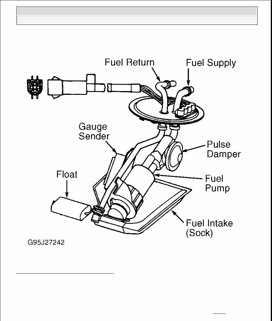
Fig. 3: Identifying Fuel Pump Components
Courtesy of FORD MOTOR CO.
Fuel Pressure Regulator
Fuel pressure regulator controls fuel pressure supplied to injectors. Fuel pressure regulator is attached to fuel
supply manifold assembly, downstream of fuel injectors. Regulator is diaphragm operated. One side of
diaphragm senses fuel pressure, and other side is subjected to intake manifold pressure. See Fig. 4 .
1996 Ford Thunderbird LX
E - THEORY/OPERATION - 4.6L 1996 ENGINE PERFORMANCE Ford Motor Co. - Theory & Operation - EEC-V
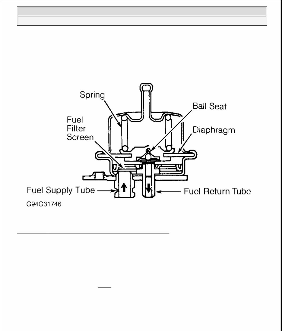
Fuel pressure is controlled by spring preload applied to diaphragm. Balancing one side of diaphragm with
manifold pressure maintains constant fuel pressure at injectors. Excess fuel supplied by pump, but not
consumed by engine, passes through regulator and returns to fuel tank through fuel return line.
Fig. 4: Cross - Sectional View Of Pressure Regulator Components
Courtesy of FORD MOTOR CO.
Inertia Fuel Shutoff (IFS) Switch
In the event of a collision or vehicle rollover, electrical contacts within the inertia switch trip open and voltage
supply to the electric fuel pump is shut off.
If the electrical circuit trips, it is not possible to restart the vehicle until the switch is reset. A reset button is
located on the switch assembly. See Fig. 5 .
WARNING: DO NOT reset IFS switch until complete fuel system has been inspected
for leaks.
1996 Ford Thunderbird LX
E - THEORY/OPERATION - 4.6L 1996 ENGINE PERFORMANCE Ford Motor Co. - Theory & Operation - EEC-V
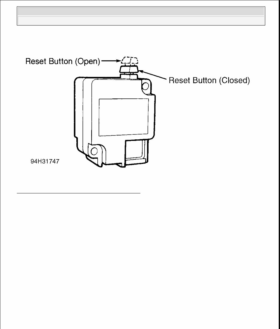
Fig. 5: Identifying IFS Reset Button Switch Positions
Courtesy of FORD MOTOR CO.
FUEL CONTROL
Fuel Injectors
The PCM controls fuel injector ON time to meter fuel quantity into intake ports. The PCM receives inputs from
engine sensors to compute fuel flow necessary to maintain correct air/fuel ratio throughout entire engine
operating range. Injector ON time pulse width is the only controlled variable in fuel delivery system.
Each cylinder has a solenoid-operated injector that sprays fuel toward the back of each intake valve. Fuel
injector nozzles are solenoid-operated valves, which meter and atomize fuel delivered to engine. Each injector
receives battery voltage through an ignition switch circuit. The PCM-controlled ground circuit is used to
complete the circuit and energize the injector.
Injector bodies consist of solenoid-actuated pintle and needle valve assembly. Injector flow orifice is fixed and
fuel pressure at injector tip is constant. Fuel flow to engine is regulated according to length of time solenoid is
energized. This period is known as pulse width. Atomized spray pattern is obtained by shape of pintle.
IDLE SPEED
Idle Air Control (IAC) Valve Assembly
1996 Ford Thunderbird LX
E - THEORY/OPERATION - 4.6L 1996 ENGINE PERFORMANCE Ford Motor Co. - Theory & Operation - EEC-V
You're Reading a Preview
What's Included?
Fast Download Speeds
Offline Viewing
Access Contents & Bookmarks
Full Search Facility
Print one or all pages of your manual
$36.99
Viewed 41 Times Today


Secure transaction
What's Included?
Fast Download Speeds
Offline Viewing
Access Contents & Bookmarks
Full Search Facility
Print one or all pages of your manual
$36.99
Introducing the 1996 Mercury Cougar Service & Repair Manual Software.
Whether you are a professional mechanic or a DIY enthusiast, this software is essential for anyone looking to service and repair a 1996 Mercury Cougar. With step-by-step instructions, detailed illustrations, and comprehensive wiring diagrams, this manual software provides everything you need to efficiently and effectively maintain your vehicle.
Key Features:
- Complete coverage for all 1996 Mercury Cougar models:
- - Base Model
- - XR7
- - XR7 Anniversary Edition
- Highly detailed repair procedures
- Diagnostic codes and troubleshooting charts
- Electrical wiring diagrams
- Component location diagrams
- Exploded views and illustrations
- Torque specifications
- And much more!
Don't waste time and money on guesswork. Invest in the 1996 Mercury Cougar Service & Repair Manual Software today and keep your Cougar running at its best.


