1988 Mercedes-Benz 300E (W124) Service & Repair Manual
What's Included?
Lifetime Access
Fast Download Speeds
Online & Offline Access
Access PDF Contents & Bookmarks
Full Search Facility
Print one or all pages of your manual
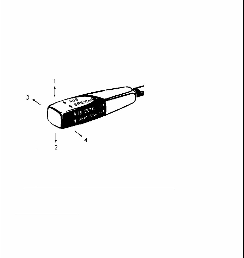
CRUISE CONTROL SYSTEM 1988 CRUISE CONTROL SYSTEM Mercedes-Benz DESCRIPTION The electronic cruise control system consists of a control unit, electric control motor and a 4-position control lever. The 4 positions are: "1" - ACCELERATE/SET, "2" - DECELERATE/SET, "3" - CANCEL/OFF and "4" - RESUME. Fig. 1: Control Lever Positions Courtesy of MERCEDES-BENZ OF NORTH AMERICA. OPERATION CRUISE CONTROL SYSTEM The cruise control will maintain any desired speed above approximately 25 MPH. To set cruise control, accelerate vehicle to desired speed. Briefly push control lever to position "1" or "2". The accelerator may now
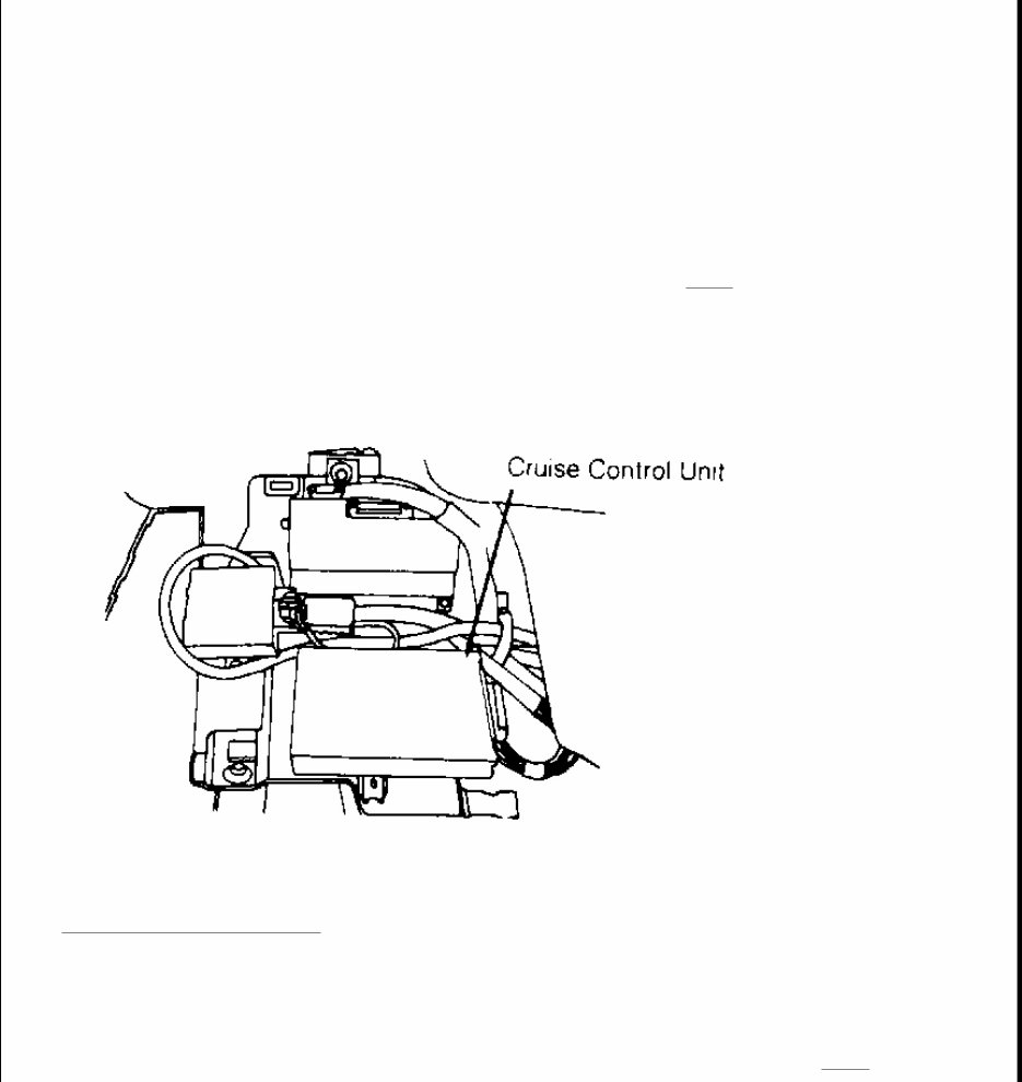
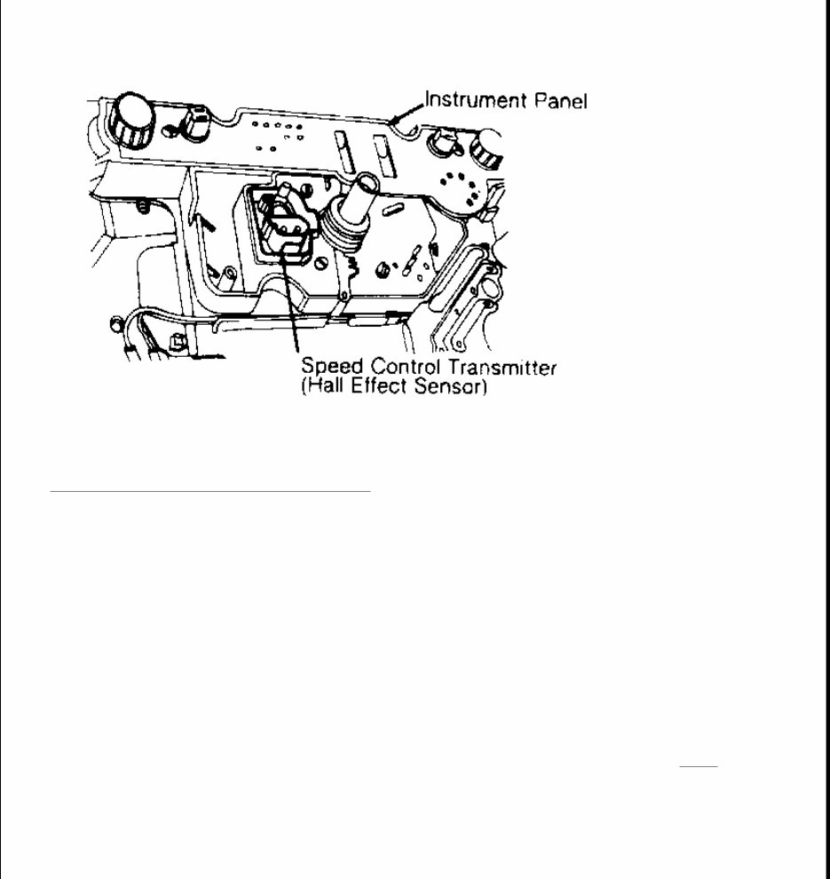
be released. Speed may be increased for passing by using accelerator pedal. As soon as accelerator pedal is released, previously set speed will be resumed. If set speed is to be changed, hold lever in position "1" or "2" until desired speed is reached. When lever is released, the new speed will be set. If the brake pedal is actuated, cruise control operation is canceled. CONTROL UNIT On 260 and 300E models, control unit is mounted under left side of instrument panel. On all other models, control unit is located behind passenger kick panel. The control unit compares actual and set speed. If speeds differ, the control unit activates the control motor to attain desired speed. See Fig. 2 . The control unit is fitted with a replaceable reference resistor which allows specifications to differ between various models while allowing utilization of the same control unit for all models. Fig. 2: Control Unit Mounting Courtesy of MERCEDES-BENZ OF NORTH AMERICA. TRANSMITTER The speed control (Hall Effect) transmitter is located on the back of the speedometer. The speed control transmitter receives the actual speed signals and sends this information to the control unit. See Fig. 3 .
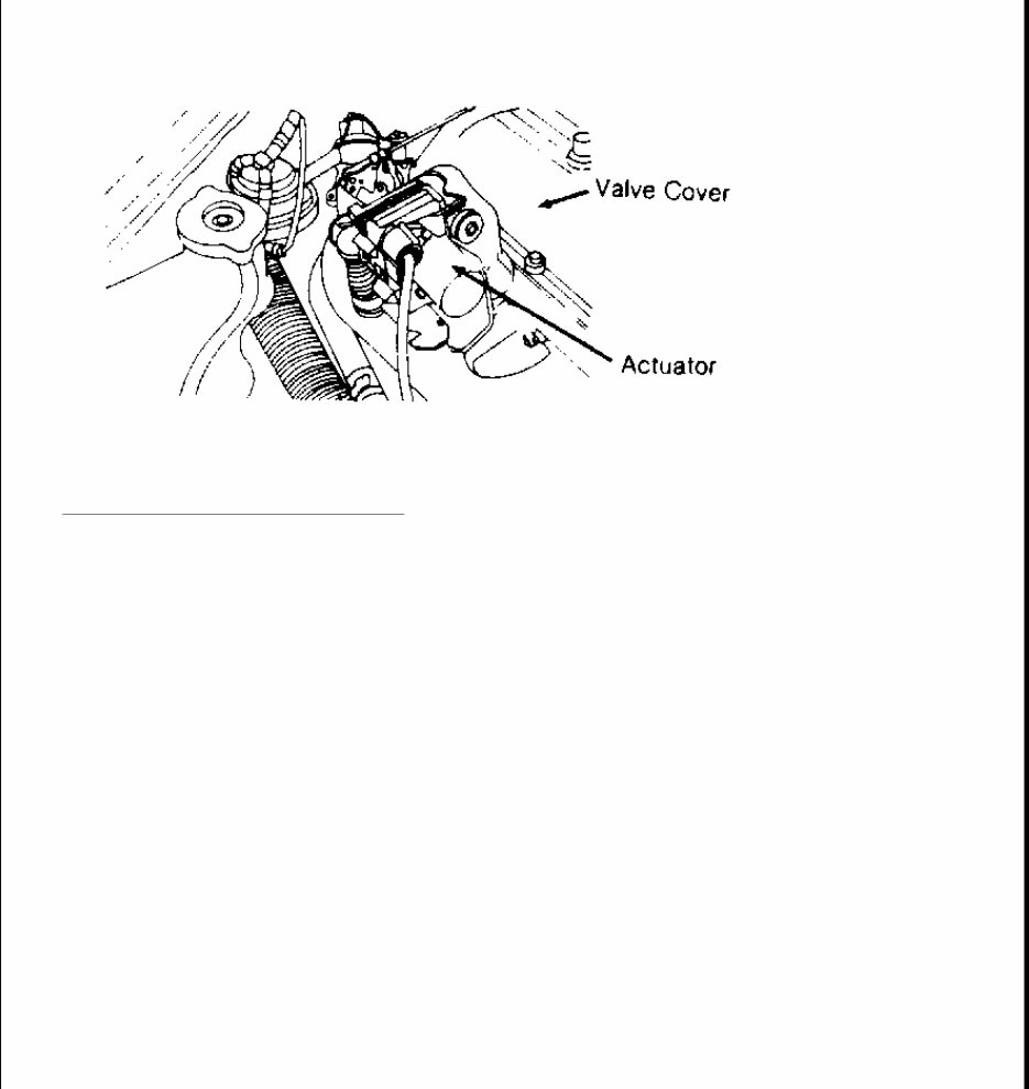
Fig. 3: Location of Speed Control Transmitter Courtesy of MERCEDES-BENZ OF NORTH AMERICA. ACTUATOR The actuator receives control signals from the control unit and actuates regulating linkage by using a connecting rod. The actuator is comprised of an electric motor with gear unit, one-way clutch, potentiometer and an electromagnetic clutch. The actuator output shaft is driven by the electric motor, through a gear reduction and a one-way clutch. The one-way clutch permits accelerator pedal use independent of cruise control actuator. The potentiometer relays position of output shaft to the control unit. The electromagnetic clutch transmits power from the electric motor to the output shaft. The electromagnetic clutch interrupts shaft movement when brake or clutch pedal is depressed. Movement is also interrupted when system is switched off at control switch or when regulating linkage is at idle speed position. See Fig. 4 .
Fig. 4: View of Cruise Control Actuator Courtesy of MERCEDES-BENZ OF NORTH AMERICA. CLUTCH PEDAL SWITCHING RELAY During cruise control operation, the switching relay will shut off the deceleration mode. The relay is painted Yellow and is located in main/fuse relay box. ADJUSTMENTS ACTUATOR CONNECTING ROD Disconnect actuator rod at throttle linkage. Ensure throttle linkage is against idle stop. With actuator against idle stop, adjust actuating rod about .039" (1.0 mm) shorter than length necessary to refit to throttle linkage. Reconnect actuator rod to throttle linkage. TROUBLE SHOOTING CRUISE CONTROL INOPERATIVE WARNING: When performing work on vehicles equipped with SRS (Supplement Restraint System), exercise extreme caution when working around steering wheel or column. DO NOT apply electrical power to any component on steering column without disconnecting SRS control unit. Air bag system may be activated, possibly causing personal injury.
Check harness connection at control unit. Test control unit using Test Adapter (126 589 05 21 00). CRUISE CONTROL SWITCHES OFF BUT CAN BE RESET Replace control unit. CRUISE CONTROL WILL ONLY ENGAGE ABOVE 35 MPH Ensure control unit and reference resistor numbers are correct. Test for continuity at control unit connector, between terminals No. 14 and 12. OPERATION ERRATIC THROUGH ENTIRE SPEED RANGE Ensure control unit and reference resistor numbers are correct. Check connection at speed transmitter on back of speedometer. If connections are correct, replace actuator. OPERATION ERRATIC WHEN DRIVING DOWNHILL OR ON LEVEL ROAD Check cruise control harness connections. Disconnect microswitch plug and connect directly to cruise control harness. Connect remaining cruise control connector to microswitch. Road test vehicle. ACTUATOR NOISY WHEN IGNITION IS SWITCHED ON Check connections at actuator and control unit. Ensure contacts are servicable. Replace actuator if necessary. THROTTLE PEDAL WILL NOT GO TO FULL POSITION 1. Test actuator and ground connections for continuity. If correct, replace actuator. 2. Ensure that cruise control function is canceled during braking. Push switch "M" on test adapter. Throttle control and accelerator pedal should move to full position. Depress brake pedal. 3. Throttle control and accelerator pedal should immediately move into idle speed position. If so, testing is complete. If test is not to specification, check throttle control for ease of operation. If necessary, replace actuator. 4. On vehicles with manual transmission, test cruise control cutout during clutch operation. Push button "M" on test adapter. If throttle control and accelerator move to full throttle position, depress clutch pedal. If throttle control and accelerator pedal are not moving immediately into full throttle position, replace actuator. 5. Depress brake pedal, if throttle control and accelerator pedal do not move into idle position, replace actuator. If okay, testing is complete. TESTING TEST PREPARATION 1. Access control unit and remove 14-pin connector. If factory tester is being used, connect Test Adapter
(126 589 05 21 00) to 14-pin connector. If testing with multimeter refer to VOLTAGE & RESISTANCE CHECKS table. Turn on ignition. The LED symbols for battery and ground should be on, provided no fault is found. 2. Push LED test button and check that all LED readouts are on. If no LED's are on, test connectors at voltage supply and cruise control. If correct, replace control unit. 3. If LED lights are on, go to next test. If LED lights are not on, test control switch connector. Replace control switch, if necessary. CONNECTOR IDENTIFICATION FUNCTION CHECKS Terminal No. 8 of control unit must be grounded for cruise control to operate. When brake pedal is depressed, brake switch closes and voltage to brake lights electrically interrupts ground circuit to control unit, cancelling operation. Power is supplied through fuse No. 5 (8 amp) to terminal No. 1 (control unit), terminal No. 2 (control switch) and terminal No. 1 (speed sensor). REMOVAL & INSTALLATION CONTROL UNIT Removal & Installation Remove floor mat on passenger side. Remove cover for cruise control unit. Pull connector from control unit. Unscrew control unit from cover and remove from vehicle. On 260 and 300E models, control unit is mounted under left side of dash. To install, reverse removal procedure. Perform road test. CLUTCH PEDAL SWITCH Removal & Installation Remove cover under instrument panel on driver's side. Pull harness from switch. Loosen switch and remove. To install, reverse removal procedure. Perform road test. ACTUATOR Removal & Installation 1. Disconnect battery. Separate plug connection. Open cable straps and expose harness at actuator. Remove Connector Size Location Actuator 8-Pin Engine Compartment Speed Sensor 2-Pin Behind Speedometer Brake Switch 2-Pin Below LH Side of Dash Control Switch 5-Pin Below Steering Column Control Unit 14-Pin At Control Unit
ignition distributor cover and distributor finger. Loosen distributor and turn clockwise toward engine and remove. 2. Disconnect connecting rod on actuator. Remove holder with actuator. Remove holder and lever from actuator. 3. To install, reverse removal procedure. Turn output shaft of actuator in opposite direction of arrow against stop. Refit lever and tighten lock nut. 4. Adjust actuator operating rod. See adjustment procedure in this article. Reset ignition timing. Road test vehicle. CONTROL SWITCH Removal & Installation 1. Disconnect battery. Remove cover on driver's side under instrument panel. Pull plug from connector. Disconnect SRS control unit and CAREFULLY remove steering wheel and jacket tube lining. 2. Disconnect clamps on combination switch. Remove mounting screws together with snap rings. Release cruise control switch from combination switch and remove. To install, reverse removal procedure. Reconnect SRS control unit. Road test vehicle. WIRING DIAGRAMS NOTE: See the WIRING DIAGRAM article in the WIRING DIAGRAM section.
INSTRUMENT PANEL 1988 SWITCHES & INSTRUMENT PANELS Mercedes-Benz DESCRIPTION Instrument cluster includes speedometer, clock, fuel gauge, oil pressure gauge, temperature gauge and, on some models, a tachometer. All gasoline engine vehicles are equipped with a vacuum gauge. OPERATION Speedometer on 300SDL, 420SEL and 560SEL models is electronic, with a sending unit in the rear of the transmission. Speedometer on other models is cable driven. The 300SDL, 420SEL and 560SEL models use an electric oil pressure sending unit. All other models have an oil pressure line to the instrument cluster. Fuel and temperature gauges on all models use variable resistance sending units. Diesel models have a vacuum switch incorporated with the ignition switch to stop engine operation. This switch controls vacuum supply to the vacuum control unit. TESTING ELECTRONIC SPEEDOMETER 1. Remove sender screw and pull unit from transmission tail housing. Turn ignition on. Place a large screwdriver blade across sender tip. 2. Move blade quickly off and on sender. Speedometer needle should move slightly. If needle does not move, remove instrument cluster and unplug connector at back of cluster. 3. Connect negative lead of voltmeter to pin No. 3 and positive lead to pin No. 5. Repeat steps 1) and 2). If voltage is indicated, speedometer is defective. If there is no voltage, replace sender and harness. ELECTRIC OIL PRESSURE GAUGE 1. Turn ignition on and remove wire from sending unit. Gauge should indicate about 43 psi (3 kg/cm 2 ). If not, check sending unit wire for short to ground. If wire is okay, replace gauge. 2. Connect wire to ground. Gauge should indicate no pressure. If reading remains high, sending unit wire is broken. Check sending unit resistance. See the OIL PRESSURE SENDING UNIT RESISTANCE table. OIL PRESSURE SENDING UNIT RESISTANCE CAUTION: On models with Supplemental Restraint System (SRS), observe the following precautions: Before starting repairs, disconnect battery ground and 10-pin SRS connector under passenger's foot rest. Use extreme caution when working around steering column. SRS is identified by a SRS light below tachometer.
EXTERIOR LIGHT FAILURE INDICATOR System uses a light monitoring control unit and a dash indicator light. When the bulb of an exterior light fails, dash indicator light is turned on. 1. Turn ignition switch to "2" position. Indicator light should glow. Light should go out when engine is started. When light is brightly lit, a light failure is indicated. 2. If light remains lit until ignition switch is returned to "0" or "1" position, a brake light or turn signal light has failed. These circuits are connected to a memory circuit. 3. With exception of brake lights and turn signals, indicator light will light when any circuit with a failed bulb is in use. Since most circuits have multiple bulbs, a visual check is necessary to determine failed bulb location. FUEL GAUGE Production Up To August, 1988 1. Connect ohmmeter between terminal "G" and terminal No. 31 on fuel gauge sender. See Fig. 1 . Resistance should be 2 +/- 1 ohms with float at "FULL" position and 80 +/- 3 ohms with float at "EMPTY" position. The higher the fuel level, the lower resistance will be. 2. Connect ohmmeter across terminal "W" and terminal No. 31. Continuity should exist only if tank is empty (low fuel warning contacts). If sending unit is functional and wire harness is good, replace fuel gauge. Pressure: psi (kg/cm 2 ) Resistance: (Ohms) 0 (0) 10 14 (1) 70 28 (2) 130 43 (3) 185 NOTE: When connecting any additional lighting equipment, ensure power connection is made to fuse circuit ahead of light monitoring control unit. This will avoid malfunction or damage to control unit
Fig. 1: Fuel Sending Unit Terminal Identification Courtesy of MERCEDES-BENZ OF NORTH AMERICA. Production As Of September, 1988 1. Connect ohmmeter between terminal "G" and terminal No. 31 on fuel gauge sender. See Fig. 1 . Resistance should be 2 +/- 1 ohms with float at "FULL" position and 76 +/- 1 ohms with float at "EMPTY" position. The higher the fuel level, the lower resistance will be. 2. Connect ohmmeter across terminal "W" and terminal No. 31. Continuity should exist only if tank is empty (low fuel warning contacts). If sending unit is functional and wire harness is good, replace fuel gauge. VACUUM GAUGE 1. Locate vacuum source hose at 4-way connector near engine. Check for vacuum. If there is vacuum, connect directly to vacuum gauge hose and by-pass connector. If there is no vacuum, clean vacuum port or repair hose. 2. If vacuum gauge works, air conditioning system has a vacuum leak. If gauge does not work, repair vacuum line or replace gauge. REMOVAL & INSTALLATION INSTRUMENT CLUSTER 190 SERIES 1. Disconnect negative battery cable. Remove cover under left side of instrument panel. Remove left instrument panel vent hose from below. Unscrew speedometer cable from below.
Get your hands on the 1988 Mercedes-Benz 300E (W124) Service & Repair Manual to tackle vehicle issues like a pro. This comprehensive manual equips you with the manufacturer's recommended troubleshooting charts and replacement procedures, featuring step-by-step instructions, clear images, and exploded-view illustrations. Whether you're a professional mechanic or a DIY enthusiast, this manual is your go-to resource for maintaining and repairing your vehicle.
Regular maintenance is crucial for the longevity of your vehicle. Over time, certain parts will wear out and require replacement. With this manual at your disposal, you can save on repairs, enhance your vehicle's reliability, and minimize trips to the repair shop. Say goodbye to flipping through countless pages or dealing with greasy, torn, or lost pages. This digital manual allows for easy navigation, searchability, and portability, making it more convenient than a traditional bound manual.
Prefer a physical copy? No problem – you can easily print out the manual. It's also compatible with various electronic devices, including PC, Mac computers, Android and Apple smartphones, and tablets. All you need is Adobe Reader, available for free, to access this valuable resource.
Printable: Yes
Language: English
Compatibility: PC, Mac, Android, Apple devices, etc.
Requirements: Adobe Reader (free)
Recently Viewed
5,521,897Happy Clients
2,594,462eManuals
1,120,453Trusted Sellers
15Years in Business
Price:
Actual Price:
1988 Mercedes-Benz 300E (W124) Service & Repair Manual