Transporters • Electrical System VITO/VIANO (Model 639) Wiring Diagrams Technical training for Customers r As at 06/05 a mb
Wiring Diagram Manuals Part Number: Z6517 2111 02 This document is intended solely for use in training and is not subject to regular updating. Part numbers and documentation included in this document may change and the latest information should always be used. Printed in England 2005 Copyright DaimlerChrysler UK LTD Publisher: Mercedes-Benz CV Electrics & Telematics Team This document with all its sections is protected under the laws of copyright. Its use for any purpose whatsoever requires the prior written consent of DaimlerChrysler UK LTD. This applies in particular to its reproduction, distribution, modification, translation, recording on microfilm or storage and/or processing in electronic systems, including databases and on-line services. Note: The term »employees« does not imply any preference of gender and incorporated male and refers to male and female employees alike.
06/05 Transporters • Electrics <>Van - Electrical Systems Wiring Diagrams VITO (Model 639) Contents Chapter Title 1 Use of wiring diagrams 2 Abbreviations for wiring diagrams 3 Location and assignment of ground points 4 Location and assignment of plug connectors 5 Battery starting charging circuit 6 Voltage supply fuses 7 Fuse and relay board (SRB) 8 Signal Acquisition and actuation module (SAM) 9 Exterior lights 10 Central locking 11 CAN bus 12 Instrument cluster (IC) 13 Electronic ignition switch (EIS) 14 Electronic stability control (ESP) 15 Common rail diesel injection (CDI) 16 Standard heater
06/05 Transporters • Electrics <>Van - Electrical Systems Wiring Diagrams VITO (Model 639) Use of Wiring Diagrams Chapter 1
OV00.01-S-1901-03VA Use of wiring diagrams The wiring diagrams are prepared as function diagrams or control a Wiring diagrams unit diagrams and are built up as follows: The wiring diagrams are assigned to the familiar function groups a -Function diagrams 00-91. The systems are listed alphabetically with an indication of The control units and electrical components belonging to the the function group/ function subgroup in the "Search aid for all function are shown as symbols. The functional connections are wiring diagram groups" realized by direct lines or by the data bus. OV00.01-S-1901VA or A3 (paper version). -Control unit diagrams The wiring diagrams are filed in the respective function group a Control units are represented complete with all connected arranged according to the PE number, components. The feed of the control units appears first. e.g.: PE07.16-S-2000VA The wiring diagrams also contain linkages of possible versions and PE07.16-S-2000IVB functions. To check the completeness of the volume the sequence of the Linkages, recognizable as versions, are framed and provided with wiring diagrams filed can be seen from the lists of contents of the an abbreviated designation/ abbreviation. respective function group. For supplements the wiring diagrams The versions are designated with 1 should be filed as per the supplement sheet. and 2 e.g.: PE00.19-P-1100VA Overview of wiring diagrams.... ------------------------------------------------------------------------------------- ----------------------------------------------------------------------------------- Notes on the accompanying documents for connectors/ terminal a blocks (B1) Special equipment (SA) is specifically highlighted in the notes column. For connectors, which are installed in special equipment, the special equipment is specified in the notes column in the row in front of the connector designation. For connectors, which are installed as standard, special equipment specification is noted directly at the respective jack and/or connector. The feed of the terminal blocks is shown by means of an arrow pointing to the left, the outputs by means of arrows pointing to the right. The grouping of the individual variants/ special equipment (SA) is highlighted by means of broken lines. All outputs to components, which are installed as standard, are listed up to the first broken line.
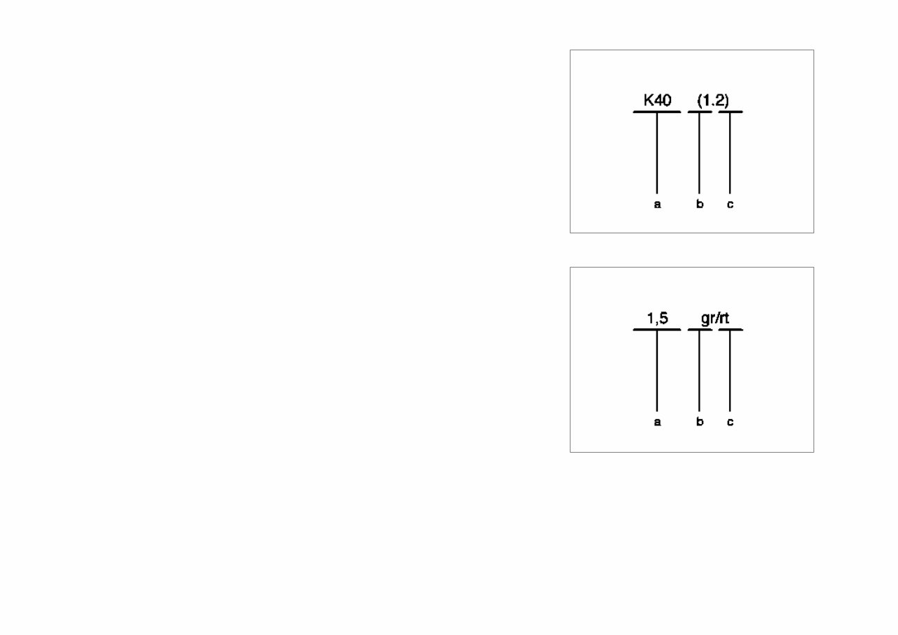
Connection designation a Component b Clutch c Socket P00.19-0402-01 Wire designation 2 a Conductor cross-section in mm b Basic color c Identification color P00.19-0403-01
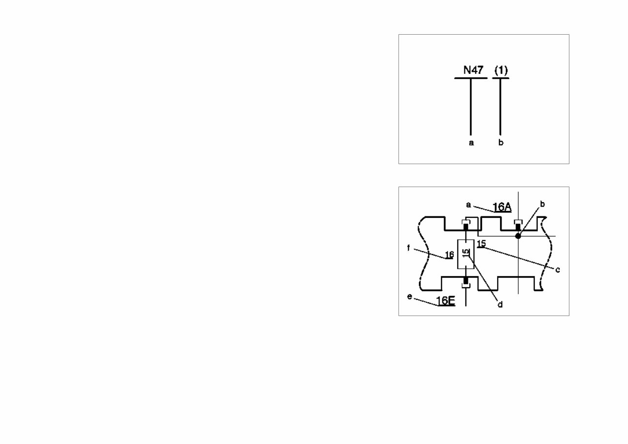
Identification of truncated wires a Component to which the truncated electric line leads b Connection designation on component Fuse blocks a Receptacle numbering, output (A, B, C or D) b Line bridge c Terminal designation d Fuse rating in amp(s) e Receptacle numbering, input (E) f Fuse number
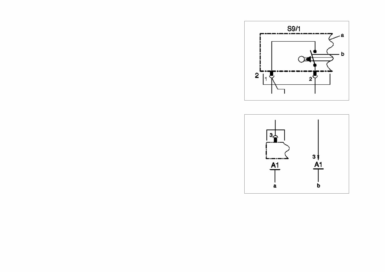
Components and switches a Component which are not represented completely are shown dismantled. b Switching contacts are shown in the rest position. a Illustration of a function-specific component with connection designation and corresponding line b Illustration of a function-independent component connection with corresponding line
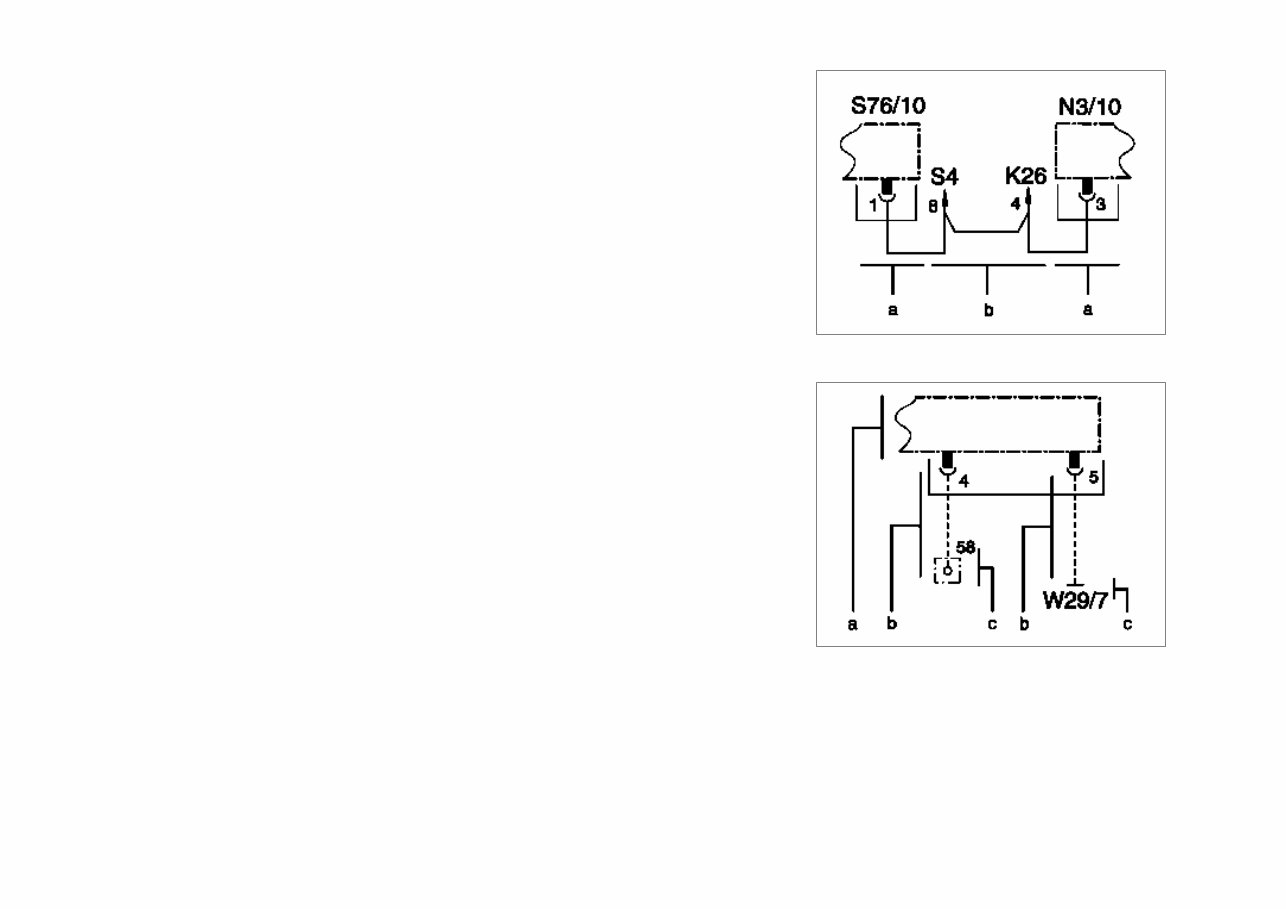
Looped lines a Function-specific components b The looped line connects two function-specific components across one or more function- independent component connections. P00.19-2089-01 Indirect line (only for terminal 31 or terminal 58) a Function-specific component b Indirect line for more than two intermediate function-independent component connections/ loops. c Connection to either terminal 31 or terminal 58
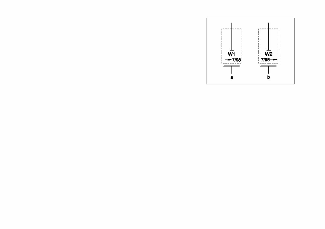
Installation date a Installation of a component up to date b Installation of a component as of date P00.19-2094-01 BK = Black = black BN = Brown = brown BU = blue = blue GN = green = green GY = gray = gray OG = orange = orange PK = pink = pink RD = red = red TR = transparent = transparent VT = violet = violet WH = white = white YE = yellow = yellow
The 2003-2014 Mercedes-Benz Vito/Viano (Model 639) Electrical Wiring Diagram Manual is a comprehensive guide that provides detailed wiring diagrams and electrical information for the Mercedes-Benz Vito and Viano models manufactured between 2003 and 2014.
Whether you are a professional technician or a do-it-yourself enthusiast, this manual is essential for accurately diagnosing and repairing electrical issues in your Mercedes-Benz Vito or Viano. It covers all electrical systems, including lighting, engine management, audio, air conditioning, and more.
With the help of this manual, you will be able to easily identify and understand the wiring connections, pin assignments, and electrical components involved in your vehicle's systems. This knowledge will enable you to effectively troubleshoot problems, perform repairs, and conduct maintenance tasks with confidence.
Key features of the 2003-2014 Mercedes-Benz Vito/Viano (Model 639) Electrical Wiring Diagram Manual include:
Clear and detailed wiring diagrams for all electrical systems
Comprehensive coverage of the Mercedes-Benz Vito and Viano models (Model 639)
Accurate pin assignments and color codes for easy identification of connections
Detailed explanations and technical information for each electrical component
A helpful troubleshooting section to assist in diagnosing electrical problems
Step-by-step instructions for performing electrical repairs and maintenance tasks
Invest in the 2003-2014 Mercedes-Benz Vito/Viano (Model 639) Electrical Wiring Diagram Manual and empower yourself with the knowledge and confidence needed to maintain and repair the electrical systems of your Mercedes-Benz Vito or Viano.

 Electrical Wiring Diagram Manual")