2008 BRAKES ABS - Service Information - Sprinter BRAKES - ABS - SERVICE INFORMATION SPECIFICATIONS TORQUE CHART TORQUE ELECTRICAL DESCRIPTION WHEEL SPEED SENSOR DESCRIPTION N.m Ft. Lbs. In. Lbs. Brake Lines To Hydraulic unit 14 10 124 Dynamics Sensor 6 - 53 Hydraulic Control Unit (HCU) Initial torque 2 - 18 Hydraulic Control Unit (HCU) Final torque 3 - 26 Wheel Speed Sensor Front 8 - 71 Wheel Speed Sensor Rear 8 - 71 2008 BRAKES ABS - Service Information - Sprinter 2008 BRAKES ABS - Service Information - Sprinter
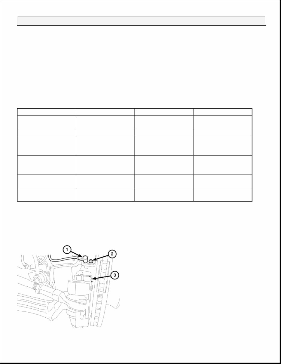
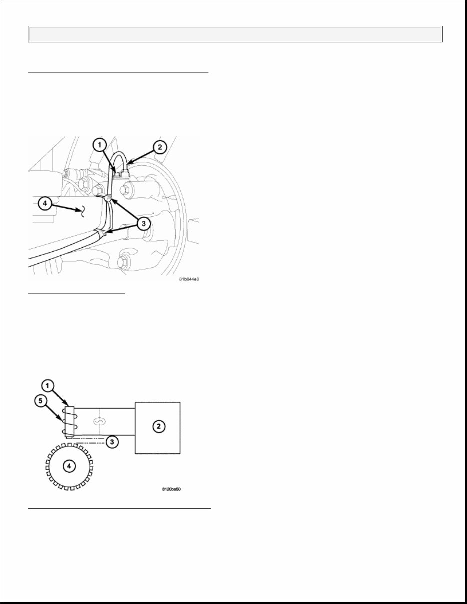
Fig. 1: Wheel Speed Sensor, Nut And Knuckle Courtesy of CHRYSLER LLC The ABS brake system uses 4 wheel speed sensors. A sensor (1) is mounted to each front knuckle (3) in the front. Fig. 2: Rear WSS Sensor Courtesy of CHRYSLER LLC A rear sensor (2) is mounted to each rear support plate. OPERATION SENSOR- WHEEL SPEED-ABS-FRONT Fig. 3: Front Wheel Speed Sensor Components Courtesy of CHRYSLER LLC The Wheel Speed Sensor consists of a magnet (1) surrounded by windings from a single strand of wire (5). The 2008 BRAKES ABS - Service Information - Sprinter
induction is created when a toothed sensor ring (exciter ring or tone wheel) (4) passes the stationary magnetic WSS. When the ring gear is rotated, the exciter ring (4) passes the tip of the WSS. As the exciter ring tooth approaches the tip of the WSS, the magnetic lines of force expand, causing the magnetic field to cut across the sensor's windings (5). This, in turn causes current to flow through the WSS circuit in one direction. When the exciter ring tooth moves away from the sensor tip, the magnetic lines of force collapse cutting the winding in the opposite direction. This causes the current to flow in the opposite direction. Every time a tooth of the exciter ring passes the tip of the WSS, an AC signal is generated current. Each AC signal (positive to negative signal or squarewave) is interpreted by the ABM. It then compares the frequency of the sinewave to a time value to calculate vehicle speed. The ABM continues to monitor the frequency to determine a deceleration rate that would indicate a possible wheel-locking tendency. The signal strength of any magnetic induction sensor is directly affected by: Magnetic field strength; the stronger the magnetic field, the stronger the signal Number of windings in the sensor; more windings provide a stronger signal Exciter ring speed; the faster the exciter ring/tone wheel rotates, the stronger the signal will be Distance (3) "air gap" between the exciter ring teeth and WSS; the closer the WSS is to the exciter ring/tone wheel, the stronger the signal will be. The WSS is not adjustable. A clearance specification has been established for manufacturing tolerances. If the clearance is not within these specifications, then either the WSS or other components may be damaged. The clearance between the WSS and the exciter ring is 0.005 - 0.050 in. The assembly plant performs a "Rolls Test" on every vehicle that leaves the assembly plant. One of the test performed is a test of the WSS. To properly test the sensor, the assembly plant connects test equipment to the Data Link Connector (DLC). This connector is located to the right of the steering column and attached to the lower portion of the instrument panel. The rolls test terminal is spliced to the WSS circuit. The vehicle is then driven on a set of rollers and the WSS output is monitored for proper operation. FRONT WHEEL SPEED SENSOR REMOVAL FRONT WHEEL SPEED SENSOR 2008 BRAKES ABS - Service Information - Sprinter
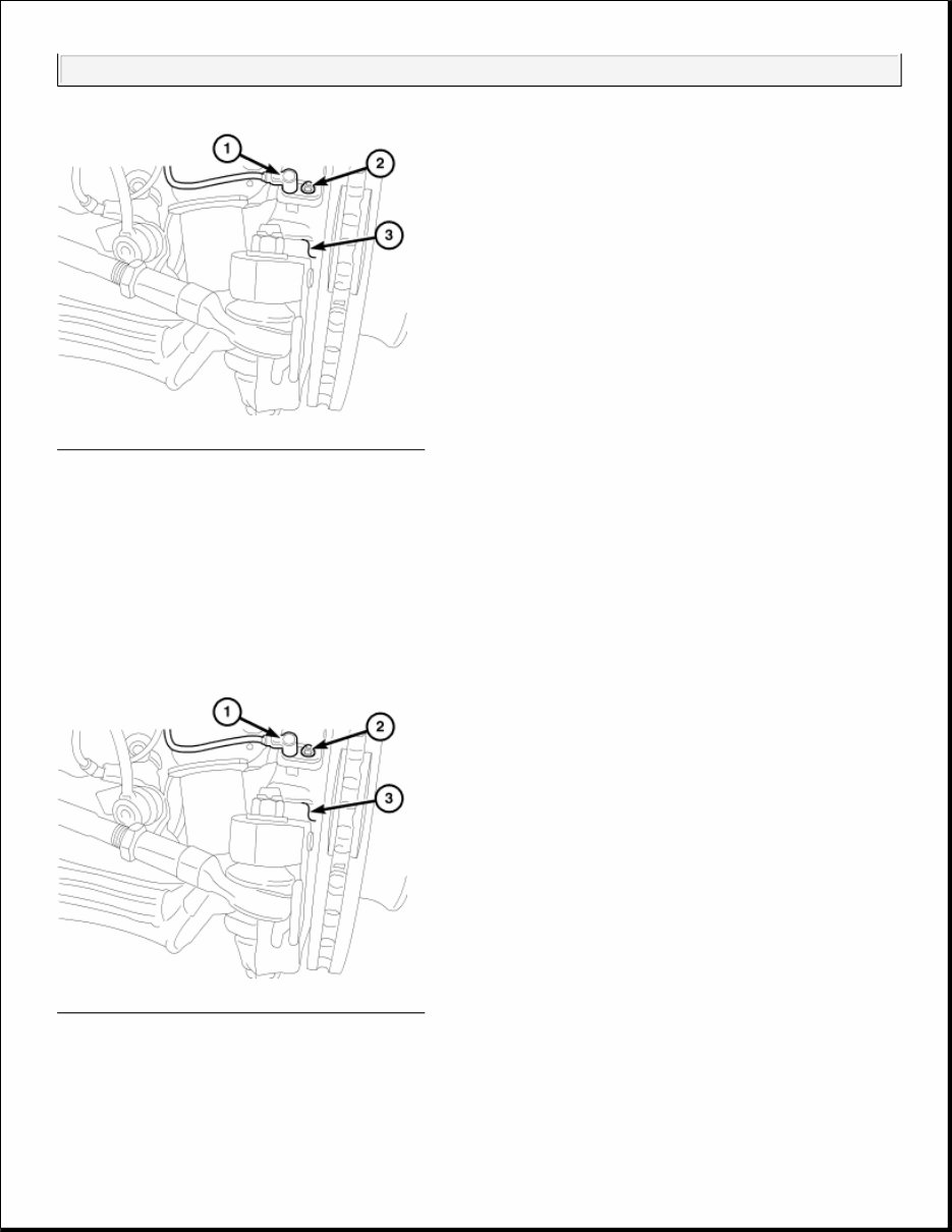
Fig. 4: Wheel Speed Sensor, Nut And Knuckle Courtesy of CHRYSLER LLC 1. Raise and support the vehicle. 2. Remove the front wheels. 3. Remove the wheel speed sensor nut (2). 4. Remove the wheel speed sensor (1) from the knuckle (3). INSTALLATION FRONT WHEEL SPEED SENSOR Fig. 5: Wheel Speed Sensor, Nut And Knuckle Courtesy of CHRYSLER LLC 1. Install the wheel speed sensor (1) all the way into the knuckle (3). Tighten the bolt (2) to 8 N.m (71in.lbs.). 2008 BRAKES ABS - Service Information - Sprinter
You're Reading a Preview
What's Included?
Lifetime Access
Fast Download Speeds
Offline Viewing
Access Contents & Bookmarks
Full Search Facility
Print one or all pages of your manual
$36.99
2011 Mercedes-Benz Sprinter 3500 (NCV3) Service & Repair Manual
2011 Mercedes-Benz Sprinter 3500 (NCV3) Service & Repair Manual
Engines covered:
3.0L V6 OM642 CDI
3.5L V6 M272
The 2011 Mercedes-Benz Sprinter 3500 (NCV3) Service & Repair Manual is the perfect guide for keeping this heavy-duty van performing reliably—whether it’s powered by the 3.0L V6 OM642 diesel or the 3.5L V6 M272 gasoline engine. Built for serious work, the Sprinter 3500 deserves equally serious maintenance, and this manual walks you through the right way to do it.
You’ll find detailed procedures for engine service, transmission removal, cooling system inspections, fuel delivery checks, suspension work, and brake overhauls. Every section includes factory torque specs, mechanical tolerances, and clear disassembly/reassembly instructions, making it easier to handle everything from routine service to deeper mechanical work.
Whether you're running a delivery fleet or wrenching on your own high-mileage hauler, this manual is a practical, no-nonsense tool. It's written for people who want to get under the van and get the job done—efficiently, correctly, and without second-guessing every turn of the wrench.
Printable: Yes Language: English Compatibility: Pretty much any electronic device, incl. PC & Mac computers, Android and Apple smartphones & tablet, etc. Requirements: Adobe Reader (free)
Reviews
Q&A
Recently Viewed
5,521,897Happy Clients
2,594,462eManuals
1,120,453Trusted Sellers
15Years in Business
Price:
Actual Price:
2011 Mercedes-Benz Sprinter 3500 (NCV3) Service & Repair Manual





 Lifetime Access




