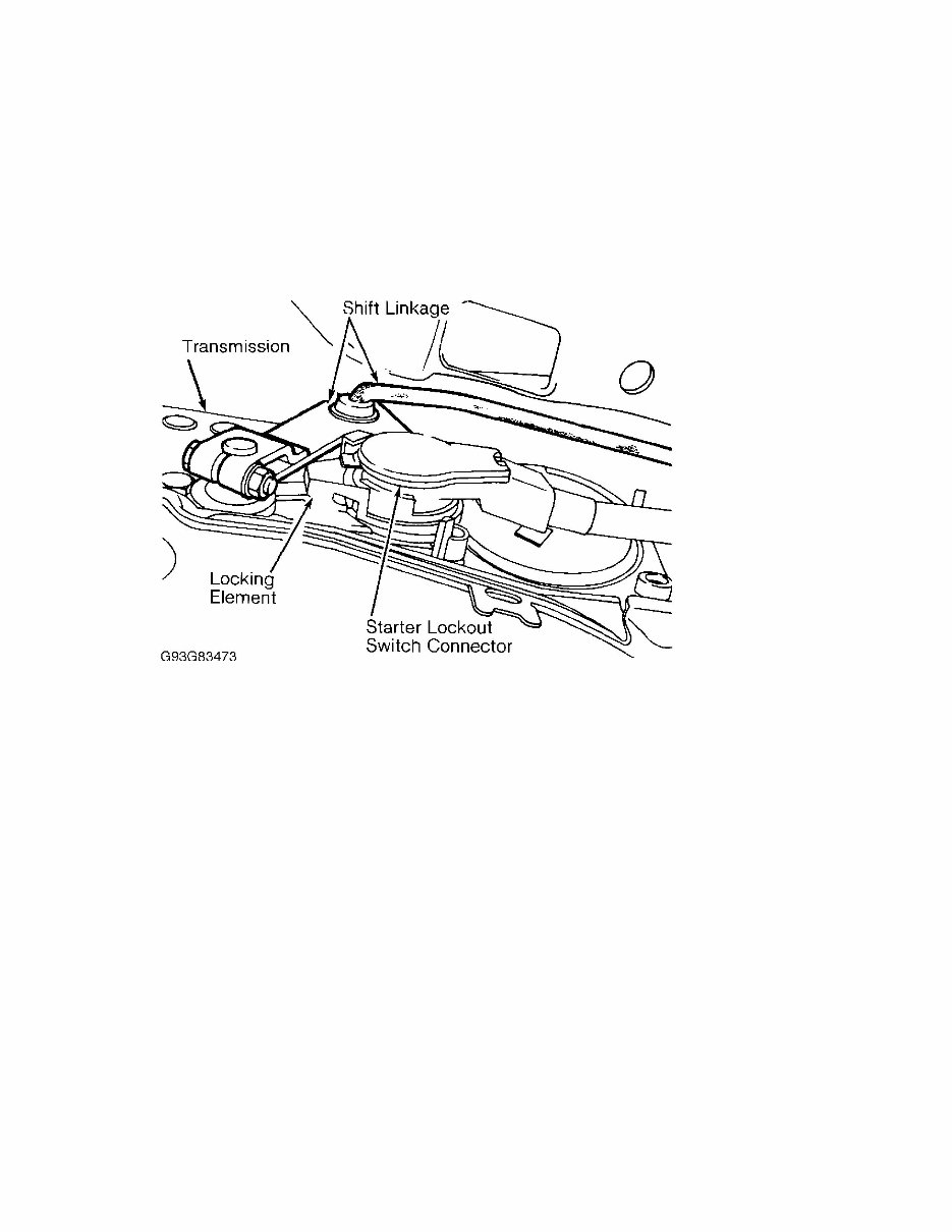
4.2L & 5.0L V8 Article Text (p. 5) 1998 Merce transmission by repositioning engine hoist several times. Installation To install, reverse removal procedure. Adjust all fluid levels. Fig. 1: Identifying Starter Lockout Switch Connector Locking Element Courtesy of Mercedes-Benz of North America. BELT TENSIONER Removal & Installation Loosen belt tensioner adjustment bolt (accessible from top front of engine). Remove belt. Remove bolt from center front of belt tensioner (accessible from front of engine). Pull belt tensioner forward, removing belt tensioner. To install, reverse removal procedure. Tighten bolt to specification. See TORQUE SPECIFICATIONS. INTAKE MANIFOLD NOTE: Removal and installation procedure is not available. EXHAUST MANIFOLD Removal & Installation (Right Side) Disconnect negative battery cable. Disconnect dipstick guide tube from exhaust manifold. Disconnect exhaust manifold from exhaust pipe. Remove exhaust manifold retaining bolts. Raise engine slightly to assist in removal of exhaust manifold. Remove exhaust manifold. To install, reverse removal procedure. Install NEW exhaust manifold gasket with metal side facing cylinder head. Removal & Installation (Left Side)
4.2L & 5.0L V8 Article Text (p. 6) 1998 Mercedes-Benz SL500For 1 Copy Disconnect negative battery cable. Remove radiator shroud. Disconnect left engine mount. Disconnect exhaust manifold from exhaust pipe. Remove exhaust manifold retaining bolts. Raise engine slightly to assist in removal of exhaust manifold. Remove exhaust manifold. To install, reverse removal procedure. Install new exhaust manifold gasket with metal side facing cylinder head. CYLINDER HEAD Removal 1) Raise hood to vertical position. Release fuel pressure. See FUEL PRESSURE RELEASE under REMOVAL & INSTALLATION. Disconnect battery ground cable. Drain engine coolant from engine. Remove accessory drive belt. 2) Rotate crankshaft to 45 degrees Before Top Dead Center (BTDC). Remove intake manifold. Disconnect power steering pump with reservoir and position aside. 3) Remove crankcase ventilation lines. Remove engine wiring harness over right cylinder head valve cover. Disconnect brake servo vacuum line at intake manifold. 4) Remove covers over both distributors. Remove both distributor caps with wires. Remove distributor rotor and driver. Remove protective cover with seal. 5) Disconnect left front cylinder head cover oil line. Remove left cylinder head bracket cover (located on end of cylinder head). Remove left front cylinder head cover (located on end of cylinder head). 6) Disconnect camshaft adjuster electrical connector from right cylinder head. Remove right cylinder head bracket cover (located on end of cylinder head). Remove right front cylinder head cover (located on end of cylinder head). 7) Mark all 4 camshaft gears with colored dots to identify timing chain position. Remove timing chain tensioner. See CHAIN TENSIONER. Remove camshaft sprockets. 8) Disconnect fuel lines from fuel rail. Remove covers over spark plugs and ignition coils. Disconnect spark plug wires. Remove valve cover bolts with washers. Note different lengths of valve cover bolts during removal. 9) Remove valve covers with seals. Disconnect right cylinder head dipstick guide tube. Disconnect exhaust manifolds at exhaust manifold flange. 10) Remove first and fourth intake camshaft bearing caps. Attach Lifting Eyes (104 589 00 40 00) to intake camshaft bearing cap locations No. 1 and 4. 11) Remove 3 bolt and washer assemblies from front of cylinder head. Note different lengths of valve cover bolts during removal. Identify location of bolt and washer assemblies for reassembly. 12) With engine cold, remove cylinder head bolts in reverse order of installation. On CL500, E420, S420 and S500, cylinder head bolt No. 10 for either head (last in tightening sequence, first in removal) cannot be removed with cylinder head installed. Loosen and
4.2L & 5.0L V8 Article Text (p. 7) 1998 Merc secure left cylinder head bolt No. 10 in raised position. 13) On all models, attach hoist to lifting eyes mounted on cylinder head. Remove cylinder head bolts. Using hoist, remove cylinder head. CAUTION: Check cylinder head bolts for excessive stretching. Failure to replace stretched bolts may result in bolts breaking. Installation 1) To install, reverse removal procedure. Install new cylinder head gasket. Ensure head gasket is correctly positioned. Check length of cylinder head bolts. Cylinder head bolts stretch permanently when installed. 2) Measure from bottom of bolt head to bottom of bolt. Check cylinder head bolt length. Maximum cylinder head bolt length is 6.41" (162.7 mm). If length exceeds 6.41" (162.7 mm), replace all cylinder head bolts. 3) Oil threads and bolt head contact surface of cylinder head bolts. With engine cold, tighten cylinder head bolts to specification in proper sequence. See Fig. 2. Ensure bolt and washer assemblies (located on front of cylinder head) are installed in proper location because bolts are different sizes. See TORQUE SPECIFICATIONS. Ensure paint marks on timing chain and camshaft sprockets are aligned. To complete installation, reverse removal procedure. Fig. 2: Installing Cylinder Head Bolts Courtesy of Mercedes-Benz of North America. FRONT CRANKSHAFT OIL SEAL Removal With engine removed from vehicle, remove all accessory drive
4.2L & 5.0L V8 Article Text (p. 8) 1998 Merce belts. Mark for installation alignment reference, and remove vibration damper, pulley and hub. Using a seal remover, remove oil seal. NOTE: DO NOT use grease when installing oil seal. Grease will prevent oil from flowing back into engine. Installation Check hub for grooves. If hub is grooved, install oil seal with a .12" (3 mm) offset. Using engine oil, lubricate sealing lip of oil seal and install seal. DO NOT use grease. To complete installation, reverse removal procedure. REAR CRANKSHAFT OIL SEAL NOTE: DO NOT remove rear cover from engine when replacing rear crankshaft oil seal unless absolutely necessary. Removal 1) Rear crankshaft oil seal is located in an end cover bolted to cylinder block. Disconnect negative battery cable. Separate engine from transmission. Remove drive plate. Cover crankshaft journal with a rag. 2) Using a screwdriver, carefully remove rear seal. DO NOT damage crankshaft journal. Check sealing surface of crankshaft for damage. Check mounting hole for burrs. Remove burrs as necessary. NOTE: DO NOT use grease when installing oil seal. Grease will prevent oil from flowing back into engine. Installation 1) Check crankshaft for grooves. If crankshaft is grooved, during installation use a repair size oil seal. The repair size oil seal has a sealing lip that is .07" (1.75 mm) offset to the inside. 2) Install inner part of Seal Installer (117 589 00 43 00) onto crankshaft flange. Apply engine oil to new seal. DO NOT use grease. Place new rear seal over inner part of seal installer. Attach outer part of Seal Installer (117 589 00 43 00) to inner part of seal installer. Press new rear seal into mounting hole. CAUTION: Ensure oil seal dust lip does not rest against crankshaft, or oil leaks may occur due to pumping action. 3) Measure stretch bolts for drive plate. Measure shaft diameter between bottom of bolt head and top of threads. If shaft diameter is not within specification, replace stretch bolt. 4) Measure bolt length from bottom of bolt head to end of bolt threads. If bolt length is not within specification, replace stretch bolt. See DRIVE PLATE BOLT SPECIFICATIONS table. To complete installation, reverse removal procedure. CAUTION: Check drive plate bolts for excessive stretching. Failure to replace stretched bolts may result in bolts breaking.
4.2L & 5.0L V8 Article Text (p. 9) 1998 Mercedes-Benz S DRIVE PLATE BOLT SPECIFICATIONS Application In. (mm) Shaft Diameter Standard ...................................... .38-.40 (9.6-10.0) Minimum ................................................ .37 (9.3) Bolt Length Standard ..................................... .90-.91 (22.8-23.2) Maximum ............................................... .93 (23.5) REAR COVER NOTE: DO NOT remove rear cover from engine unless absolutely necessary. Removal 1) With engine removed from vehicle, separate engine from transmission. Remove drive plate. Remove rear cover bolts. Identify rear cover bolts during removal, as lengths may be different. 2) Using two 8-mm tapped holes in rear cover, insert bolts and press rear cover from engine. DO NOT damage oil pan gasket when pressing rear cover from engine. NOTE: Proper installation is critical, as the rear cover seals a main oil gallery. DO NOT use grease when installing oil seal. Grease will prevent oil from flowing back into engine. Installation 1) Carefully clean sealing surface on engine and rear cover. DO NOT damage sealing surfaces, or rear cover may leak. Apply sealant to sealing surface of rear cover. DO NOT let any sealant get into oil gallery in rear cover. See Fig. 3. 2) Apply engine oil between dust lip and sealing lip of rear crankshaft oil seal. Install inner part of Seal Installer (117 589 00 43 00) onto crankshaft flange. Install rear cover (with seal) over inner part of seal installer. Use care to not damage oil pan gasket when installing rear cover. 3) Install rear cover bolts. Pay attention to rear cover bolt length, as bolt length may be different depending on bolt location. Evenly tighten rear cover bolts to specification. See TORQUE SPECIFICATIONS. Remove inner part of seal installer. To complete installation, reverse removal procedure.
This service and repair manual for the 1998 Mercedes SL500 includes a comprehensive collection of over a thousand pages. It encompasses various repair and maintenance procedures, part layouts, wiring schematics, and specific part numbers tailored to your model. With this manual, there's no need to invest in costly paper service manuals. You can access everything digitally and print the necessary pages as many times as required.
Whether you're a professional mechanic, a DIY enthusiast, or an everyday car owner, this manual is an invaluable resource. Even if you have minimal experience in car repairs, this manual can help you save a significant amount of money by enabling you to undertake minor repairs on your own. Additionally, it provides the opportunity to reference extensive repair procedures before heading to the repair shop, ensuring you are well-informed about the necessary repairs and replacements, thus preventing any potential overcharging.
This manual is equally beneficial for experienced mechanics and automotive enthusiasts as it delves into the intricate details required to perform extensive repairs on various components.
With over 70 separate sections, this manual covers a wide array of topics essential for car maintenance and repair.
It is compatible with all computers using Adobe Acrobat reader, allowing you to conveniently view and print the required pages. This manual is compatible with both Mac and Windows operating systems.
Recently Viewed
5,521,897Happy Clients
2,594,462eManuals
1,120,453Trusted Sellers
15Years in Business
Price:
Actual Price:
1998 Mercedes-Benz SL500 (4.2L & 5.0L) Service and Repair Manual