

1999 Mercedes-Benz E320 Service & Repair Manual
What's Included?
Fast Download Speeds
Offline Viewing
Access Contents & Bookmarks
Full Search Facility
Print one or all pages of your manual
1998-2002 STEERING
Electronic Power Steering - 210 Chassis (With 4MATIC)
MODEL IDENTIFICATION
MODEL IDENTIFICATION (1998-1999)
MODEL IDENTIFICATION (2000-02)
PRODUCTION DATE INFORMATION
WARNING: Vehicle is equipped with Supplemental Inflatable Restraint (SIR) system.
When servicing vehicle, use care to avoid accidental air bag deployment.
SIR system-related components are located in various locations
throughout interior of vehicle, depending on application. Do not use
electrical test equipment on or near these circuits. If necessary,
deactivate SIR system before servicing components. See AIR BAG
SAFETY PRECAUTIONS and DISABLING & ACTIVATING AIR BAG
SYSTEM in AIR BAG RESTRAINT SYSTEMS article.
CAUTION: When battery is disconnected, vehicle computer and memory systems
may lose memory data. Driveability problems may exist until computer
systems have completed a relearn cycle. See COMPUTER RELEARN
PROCEDURES article in GENERAL INFORMATION before disconnecting
battery.
CAUTION: Vehicles equipped with coded radios are susceptible to damage when
battery is disconnected. Ensure ignition switch is in OFF position and
radio is turned off before disconnecting battery. Have radio code available
when disconnecting battery or removing radio. For coding procedures,
see COMPUTER RELEARN PROCEDURES article in GENERAL
INFORMATION.
Model Chassis Engine
E320 (Sedan) 210.082 112.941
E320 (Wagon) 210.282 112.941
Model Chassis Engine
E320 (Sedan) 210.082 112.941
E320 (Wagon) 210.082 112.941
E430 210.083 113.94
NOTE: Diagnostic information is divided by vehicle production date breaks. Ensure
diagnostic information being used applies to vehicle being diagnosed. The
following production date breaks are used in this diagnostic information.
2000 Mercedes-Benz E320 4Matic
1998-2002 STEERING Electronic Power Steering - 210 Chassis (With 4MATIC)
2000 Mercedes-Benz E320 4Matic
1998-2002 STEERING Electronic Power Steering - 210 Chassis (With 4MATIC)
This article covers 210 chassis (with 4MATIC) from June Of 1998 to December of 2002.
DESCRIPTION & OPERATION
COMPONENT LOCATIONS (SECTION 21)
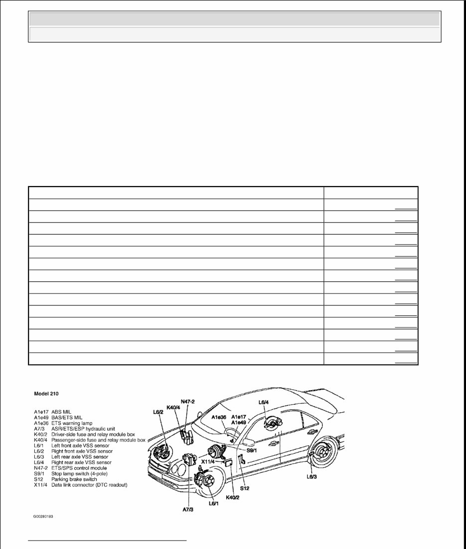
COMPONENT LOCATIONS
Fig. 1: Identifying Component Locations
Courtesy of MERCEDES-BENZ OF NORTH AMERICA.
NOTE: Vehicles may be equipped with Anti-Lock Braking System (ABS), Acceleration
Slip Regulation (ASR), Electronic Traction System (ETS), Electronic Stability
Program (ESP) and Speed-Sensitive Power Steering (SPS) systems.
Component See
ABS MIL (A1e17) Fig. 1
ASR/ETS/ESP Hydraulic Unit (A7/3) Fig. 1
BAS/ETS MIL (A1e49) Fig. 1
Data Link Connector (DTC Readout) (X11/4) Fig. 1
Driver Side Fuse & Relay Module Box (K40/2) Fig. 1
ETS/SPS Control Module (N47-2) Fig. 1
ETS Warning Lamp (A1e36) Fig. 1
Left Front Axle VSS Sensor (L6/1) Fig. 1
Left Rear Axle VSS Sensor (L6/3) Fig. 1
Parking Brake Switch (S12) Fig. 1
Passenger Side Fuse & Relay Module Box (K40/4) Fig. 1
Right Front Axle VSS Sensor (L6/2) Fig. 1
Right Rear Axle VSS Sensor (L6/4) Fig. 1
Stop Lamp Switch (4 Pole) (S9/1) Fig. 1
2000 Mercedes-Benz E320 4Matic
1998-2002 STEERING Electronic Power Steering - 210 Chassis (With 4MATIC)
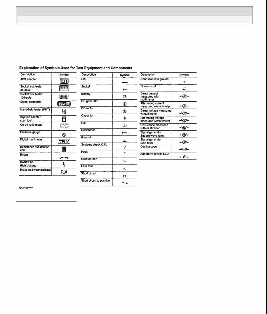
USING DIAGNOSTIC CHARTS
Use following illustrations to understand diagnostic charts and identify symbols used. See Fig. 2 - Fig. 4 .
Fig. 2: Identifying Symbols
Courtesy of DAIMLERCHRYSLER CORPORATION
2000 Mercedes-Benz E320 4Matic
1998-2002 STEERING Electronic Power Steering - 210 Chassis (With 4MATIC)
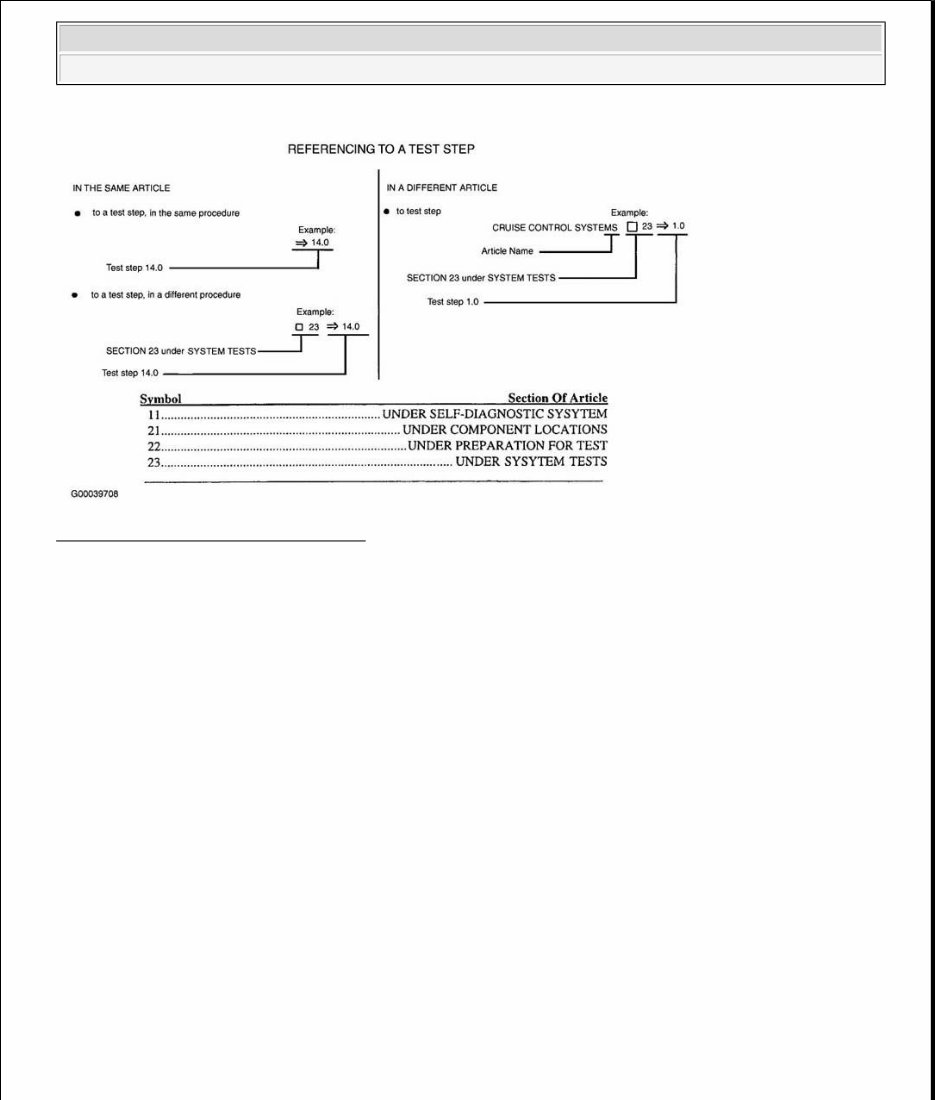
Fig. 3: Using Diagnostic Charts (1 Of 2)
Courtesy of DAIMLERCHRYSLER CORPORATION
2000 Mercedes-Benz E320 4Matic
1998-2002 STEERING Electronic Power Steering - 210 Chassis (With 4MATIC)
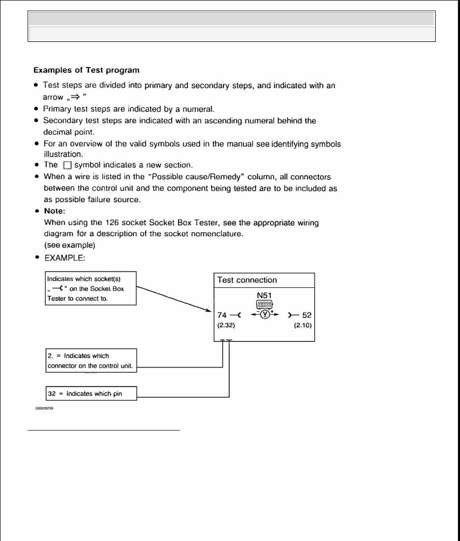
Fig. 4: Using Diagnostic Charts (2 Of 2)
Courtesy of DAIMLERCHRYSLER CORPORATION
PROGRAMMING
ACTIVATING STEERING ANGLE SENSOR
In the event that power supply is interrupted to steering angel sensor, PML control module switches to basic
function mode. Malfunction Indicator Light (MIL) in instrument cluster may illuminate. At this point steering
NOTE: For activating and initializing steering angle sensor, use the same procedure.
2000 Mercedes-Benz E320 4Matic
1998-2002 STEERING Electronic Power Steering - 210 Chassis (With 4MATIC)
You're Reading a Preview
What's Included?
Fast Download Speeds
Offline Viewing
Access Contents & Bookmarks
Full Search Facility
Print one or all pages of your manual
$31.99
Viewed 13 Times Today


Secure transaction
What's Included?
Fast Download Speeds
Offline Viewing
Access Contents & Bookmarks
Full Search Facility
Print one or all pages of your manual
$31.99
- The 1999 Mercedes-Benz E320 Service & Repair Manual is a comprehensive guide for fixing vehicle issues, suitable for both professional mechanics and DIY enthusiasts.
- It includes troubleshooting and replacement procedures recommended by the manufacturer, featuring step-by-step instructions, clear images, and exploded-view illustrations.
- Regular maintenance is essential for the vehicle's durability, and this manual provides the necessary manufacturer-recommended charts and procedures for maintenance and repairs.
- By following the manual, users can save on repairs, enhance vehicle reliability, and reduce the frequency of visits to the repair shop.
- The manual is designed for easy access to specific information without the hassle of flipping through numerous pages, making it more convenient than traditional bound manuals.
- It is available in a printable format and compatible with various electronic devices, including PC, Mac, Android, and Apple devices, with the only requirement being Adobe Reader, which is free to use.


