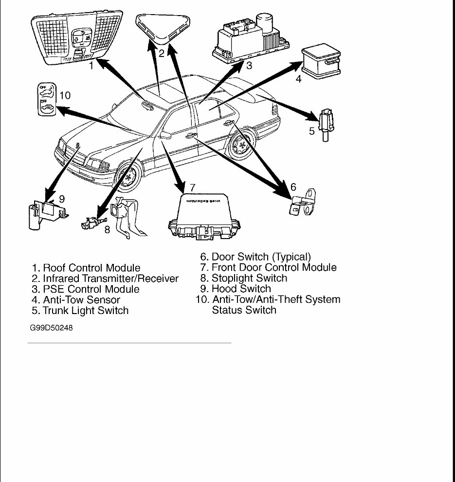
1998-99 ACCESSORIES & EQUIPMENT Anti-Theft Systems - C, CLK & E Class DESCRIPTION & OPERATION Anti-theft system is a contact controlled system. Anti-theft system is activated and deactivated by locking or unlocking doors or trunk with key or remote control transmitter. Anti-theft system is activated within approximately 15 seconds after locking vehicle. When anti-theft system is activated, an audio horn will sound and exterior lights will flash. Anti-theft system monitors radio, all doors, hood and trunk lid position. See Fig. 1 or Fig. 2 . Vehicle may also be equipped with anti-tow system. This system will trigger alarm system if vehicle is towed or raised in a manner that simulates a towing attempt. Anti-tow system can be disabled by turning ignition on and depressing switch in instrument panel. When anti-tow system is off, light in switch will come on. Anti-tow system will remain off until vehicle is locked again with key or remote transmitter. Anti-theft system is triggered when door, trunk, hood or storage compartment between seats is opened or if vehicle is lifted. When anti-theft system is triggered, an audio horn will sound for approximately 30 seconds and exterior lights will flash for approximately 2 1/2 minutes.
Fig. 1: Locating Alarm System Components (C Class) Courtesy of MERCEDES-BENZ OF NORTH AMERICA.
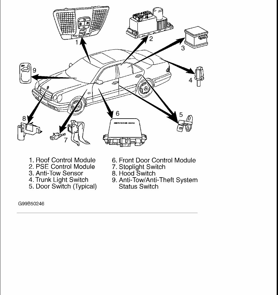
Fig. 2: Locating Alarm System Components (E Class Shown; CLK Is Similar) Courtesy of MERCEDES-BENZ OF NORTH AMERICA PROGRAMMING CONTROL MODULE NOTE: Hand-Held Tester (HHT) (965 589 00 01 00) is necessary to set control module parameters. CAUTION: When programming control module, avoid interrupting control module voltage supply. Damage to control module may result. DO NOT connect HHT to Data Link Connector (DLC) with ignition on. Damage to HHT may
Connect HHT to DLC. DLC is located in right rear corner of engine compartment. Menu item No. 5 on HHT allows programming of control modules which require programming. Only upon completion of programming is control module operational. Programming is menu driven. Follow HHT manufacturer's instructions displayed on HHT screen to program control module. Additional information is not available. FUNCTION TESTS STATUS INDICATOR LED Activating Status Indicator LED Lock vehicle and wait for approximately 15 seconds. Status indicator LED will come on and blink. If LED does not operate as specified, perform TEST 9: ANTI - TOW SENSOR under SYSTEM TESTS. LEFT FRONT DOOR Activate Anti-Theft System Using Left Front Door Open driver's door window. Lock driver's door with key. After about 15 seconds, open left front door from inside. Ensure theft alarm horn sounds and lights flash. Deactivate anti-theft system. If theft alarm horn does not sound and lights do not flash, repair driver's door switch. See appropriate wiring diagram in PNEUMATIC & POWER DOOR LOCK SYSTEMS article. RIGHT FRONT DOOR Activate Anti-Theft System Using Right Front Door Open passenger door window. Lock passenger door with key. After about 15 seconds, open passenger door from inside. Ensure theft alarm horn sounds and lights flash. Deactivate anti-theft system. If theft alarm horn does not sound and lights do not flash, repair passenger's door switch. See appropriate wiring diagram in PNEUMATIC & POWER DOOR LOCK SYSTEMS article. LEFT & RIGHT REAR DOOR Activate Anti-Theft System Using Left Or Right Rear Door Open rear door window. Lock passenger door with key. After about 15 seconds, open left or right rear door from inside. Ensure theft alarm horn sounds and lights flash. Deactivate anti-theft system. If theft alarm horn does not sound and lights do not flash, repair appropriate rear door switch. See appropriate wiring diagram in PNEUMATIC & POWER DOOR LOCK SYSTEMS article. ENGINE HOOD Activate Anti-Theft System Using Hood result.
Open driver's door window. Lock driver's door with key. After about 15 seconds, release hood by reaching through left door open window. Open hood. Ensure theft alarm horn sounds and lights flash. Deactivate anti- theft system. If theft alarm horn does not sound and lights do not flash, perform TEST 1: ENGINE HOOD SWITCH CIRCUIT under SYSTEM TESTS. TRUNK LID Activate Anti-Theft System Using Trunk Lid Open trunk lid. Lock driver's door with key. Turn off trunk light. After about 15 seconds, turn on trunk light. Ensure theft alarm horn sounds and lights flash. Deactivate anti-theft system. If theft alarm horn does not sound and lights do not flash, repair trunk lid switch. See appropriate wiring diagram in PNEUMATIC & POWER DOOR LOCK SYSTEMS article. ANTI-TOW SYSTEM Activate Anti-Theft System Using Anti-Tow System Lock vehicle and wait 15 seconds. Lift vehicle using jack until wheel is off ground. Ensure theft alarm horn sounds and lights flash. Deactivate anti-theft system. If theft alarm horn does not sound and lights do not flash, perform TEST 9: ANTI - TOW SENSOR under SYSTEM TESTS. Deactivate Anti-Tow System Turn ignition off. Press anti-tow/anti-theft system status switch located on instrument panel. Lock vehicle. Lift vehicle using jack until wheel is off ground. Theft alarm horn should not sound. If theft alarm horn sounds, perform TEST 9: ANTI - TOW SENSOR under SYSTEM TESTS. Lock vehicle and wait 15 seconds. Lift vehicle using jack until wheel is off ground. Ensure theft alarm horn sounds and lights flash. Deactivate anti- theft system. ALARM SIREN Activate Alarm Siren Using HHT Connect HHT to Data Link Connector (DLC). Activate alarm siren using HHT. Alarm siren should sound briefly. If theft alarm horn does not sound, perform TEST 5: ALARM HORN WITH AUXILIARY BATTERY under SYSTEM TESTS. PANIC ALARM Activate Anti-Theft System Using Panic Button On Transmitter Press panic button on remote transmitter located on electronic key. Ensure theft alarm horn sounds and lights flash. Deactivate anti-theft system. If theft alarm horn does not sound and lights do not flash, check battery in transmitter. HEADLAMPS
Activate Fog Lamps Turn ignition on. Turn headlights on. Turn ignition off. Turn headlights off. Fog lights will come on. If fog lights do not come on, perform TEST 15: FOGLAMPS under SYSTEM TESTS. SELF-DIAGNOSTIC SYSTEM RETRIEVING & CLEARING CODES Codes may be retrieved by connecting Hand-Held Tester (965 589 00 01 00) and Adapter Harness (965 589 00 40 00) to Data Link Connector (DLC). Follow HHT manufacturer's instructions to retrieve codes. No other information is available from manufacturer at time of publication. After codes have been retrieved, see DTC IDENTIFICATION table for description of cause of code, then perform appropriate test in SYSTEM TESTS . After repairing all DTCs, follow HHT manufacturer's instructions to clear codes using HHT. DTC IDENTIFICATION Code Cause B1220 (1) Absence Of Equipment B1221 (1) Absence Of Equipment B1276 (1) Absence Of Equipment B1277 (1) Absence Of Equipment B1278 (1) Absence Of Equipment B1279 (1) Absence Of Equipment B1435 (2) Short In Anti-Tow Sensor B1436 (3) Central Locking Safety Time Exceeded B1438 (3) Central Locking Pneumatic Demand Too High B1439 (3) Manifold Vacuum Assist Pneumatic Demand Too High B1440 (3) Remote Trunk Lid Release Pneumatic Demand Too High B1497 (1) Absence Of Equipment B1707 (1) Absence Of Equipment B1708 (1) Absence Of Equipment B1709 (4) Alarm Siren Not Installed, Not Coded Or Defective B1710 (3) Alarm Triggered By Trunk Lamp Switch B1711 (6) Alarm Triggered By Engine Hood Switch B1712 (3) Alarm Triggered By Left Front Door B1713 (3) Alarm Triggered By Right Front Door B1714 (3) Alarm Triggered By Left Rear Door B1715 (3) Alarm Triggered By Right Rear Door
SYSTEM TESTS TEST PREPARATION Ensure battery voltage is 11-14 volts. Ensure all fuses are okay. Ensure central locking system, infrared central (remote) locking system, parking lights, headlights and brakelights are operating properly. Prior to performing system tests, connect Harness Adapter (202 589 04 63 00) and Breakout Box (124 589 00 21 00) to Pneumatic System Equipment (PSE) control module. TEST 1: ENGINE HOOD SWITCH CIRCUIT B1716 (5) Reserve Alarm Input B1719 (5) Alarm Triggered By Telephone B1720 (5) Alarm Triggered By Fax Equipment B1721 (7) Alarm Triggered By Ignition System Circuit B1722 (8) Alarm Triggered By Stoplight Switch B1723 (1) Absence Of Equipment B1724 (1) Absence Of Equipment B1725 (2) Alarm Triggered By Anti-Tow Sensor B1726 (7) Circuit No. 30 Interrupted While In Armed State B1727 (1) Absence Of Equipment B1728 (1) Absence Of Equipment B1729 (9) Voltage Supply To PSE Control Module (1) Not applicable on U.S.A.vehicles. (2) Perform TEST 9 under SYSTEM TESTS. (3) Check and repair pneumatic system as necessary. See appropriate vacuum diagram or wiring diagram in PNEUMATIC & POWER DOOR LOCK SYSTEMS article. (4) Perform TEST 5 under SYSTEM TESTS. (5) Currently not used. (6) Perform TEST 1 under SYSTEM TESTS. (7) Check wiring. See WIRING DIAGRAMS . (8) Perform TEST 2 under SYSTEM TESTS. (9) Replace PSE module. NOTE: Breaks in test numbering sequence occur. No test procedures have been omitted.
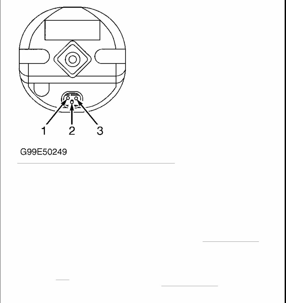
Disconnect Pneumatic System Equipment (PSE) control module harness connectors. Connect harness adapter and breakout box to Pneumatic System Equipment (PSE) control module and harness connectors. Measure voltage between terminal No. 5 on breakout box and terminal No. 4 at PSE control module harness connector No. 2. When engine hood is closed, less than one volt should exist. When engine hood is open, battery voltage should exist. If voltage is as specified, replace PSE control module. If voltage is not as specified, check wiring. See WIRING DIAGRAMS . If wiring is okay, replace engine hood switch. TEST 2: STOPLIGHT CIRCUIT Disconnect Pneumatic System Equipment (PSE) control module harness connectors. Connect harness adapter and breakout box to Pneumatic System Equipment (PSE) control module and harness connectors. Measure voltage between terminal No. 12 on breakout box and terminal No. 3 at PSE control module harness connector No. 2. Turn ignition on. When brake pedal is released, less than one volt should exist. When brake pedal is depressed, battery voltage should exist. If voltage is as specified, replace PSE control module. If voltage is not as specified, check wiring. See WIRING DIAGRAMS . If wiring is okay, replace stoplight switch. TEST 3: ALARM HORN Disconnect Pneumatic System Equipment (PSE) control module harness connectors. Connect harness adapter and breakout box to Pneumatic System Equipment (PSE) control module and harness connectors. Using a jumper wire, bridge terminal No. 3 at PSE control module harness connector No. 2 and terminal No. 4 at PSE control module harness connector No. 2. Horn should sound. If horn sounds, horn circuit is okay at this time. If horn does not sound, check wiring. See WIRING DIAGRAMS . If wiring is okay, replace alarm horn. TEST 5: ALARM HORN WITH AUXILIARY BATTERY 1. Connect scan tool to Data Link Connector (DLC). Activate alarm horn using scan tool. Alarm horn will sound briefly. If alarm horn does not sound, go to next step. 2. Disconnect connector at alarm horn. Measure voltage between terminals No. 1 and 2 at alarm horn harness connector. See Fig. 3 . Battery voltage should exist. If voltage is as specified, go to next step. If voltage is not as specified, check wiring. See WIRING DIAGRAMS . 3. Reconnect Activate anti-theft system. Wait 15 seconds. Disconnect alarm horn connector. Alarm should trigger and lights should flash. Reconnect alarm horn and deactivate alarm using remote or key. If anti- theft system operates as specified, check alarm horn. If alarm horn is okay, check wiring. See WIRING DIAGRAMS . If wiring is okay, replace Pneumatic System Equipment (PSE) control module. NOTE: Engine hood switch can be activated using HHT. Generic scan tool may not be capable of activating engine hood switch. NOTE: Alarm horn can be activated using HHT. Generic scan tool may not be capable of activating alarm horn.
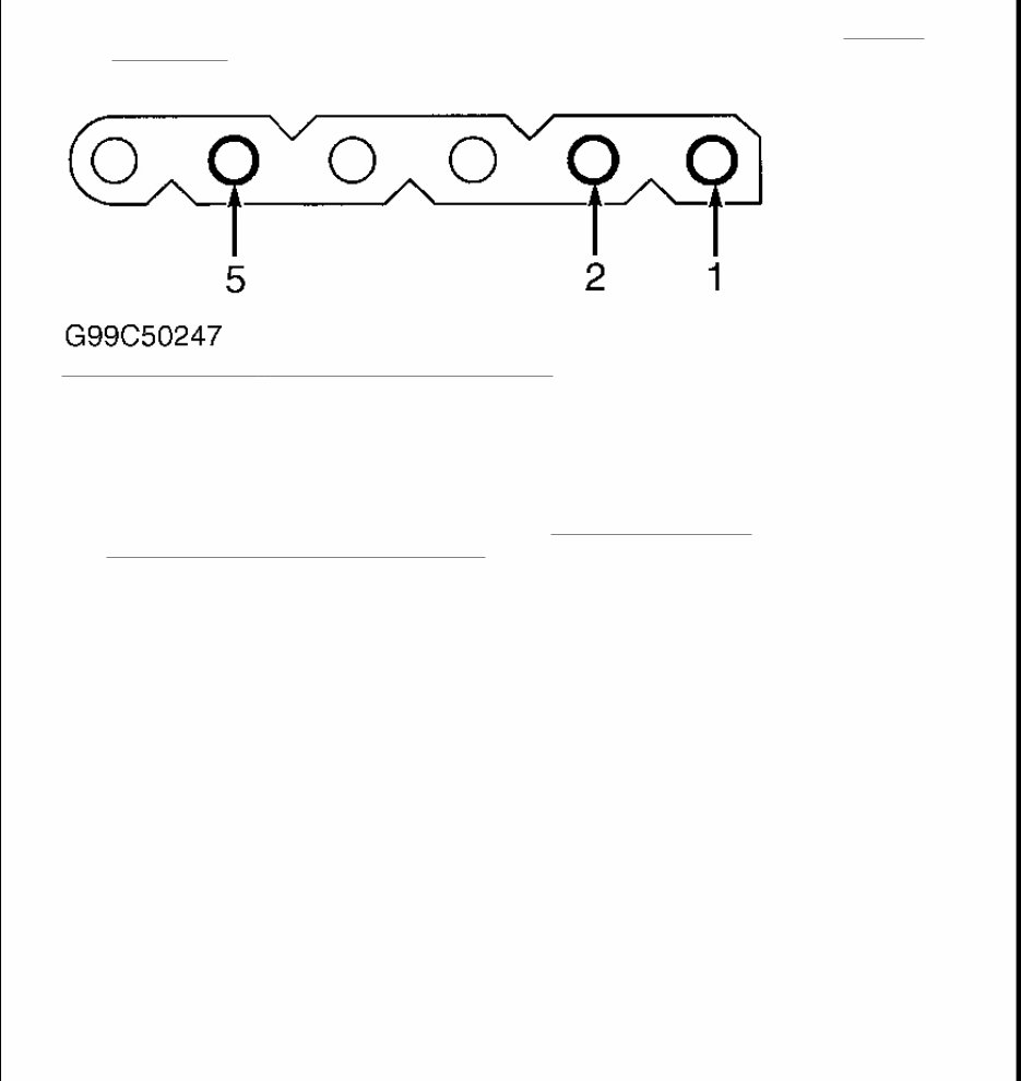
Fig. 3: Identifying Alarm Horn With Auxiliary Battery Terminals Courtesy of MERCEDES-BENZ OF NORTH AMERICA. TEST 6: HEADLIGHT ALARM CIRCUIT Disconnect Pneumatic System Equipment (PSE) control module harness connectors. Connect harness adapter and breakout box to PSE control module and harness connectors. Using a jumper wire, bridge terminal No. 4 at PSE control module harness connector No. 2 and terminal No. 1 at PSE control module harness connector No. 4. Headlights should illuminate. If headlights do not illuminate, check wiring. See WIRING DIAGRAMS . If wiring is okay, check headlight switch. Repair as necessary. TEST 9: ANTI-TOW SENSOR 1. Disconnect anti-tow sensor connector. Measure voltage between anti-tow sensor connector terminal No. 2 and 5. See Fig. 4 . Activate anti-theft system. Battery voltage should exist. If voltage is as specified, go to next step. If voltage is not as specified, check wiring. See WIRING DIAGRAMS . 2. Connect scan tool to Data Link Connector (DLC). Activate anti-tow system using scan tool. Using a jumper wire, bridge terminals No. 1 and 2 of anti-tow sensor connector. Alarm should trigger, alarm horn NOTE: No code is referred to this test. Headlight alarm circuit can be activated using HHT only. Generic scan tool may not be capable of activating headlight alarm circuit.
sounds and lights should flash. If anti-theft system operates as specified, check wiring. See WIRING DIAGRAMS . If wiring is okay, check Pneumatic System Equipment (PSE) control module. If PSE is okay, replace anti-tow sensor. Fig. 4: Identifying Anti - Tow Sensor Connector Terminals Courtesy of MERCEDES-BENZ OF NORTH AMERICA. TEST 15: FOGLAMPS Disconnect Pneumatic System Equipment (PSE) control module harness connectors. Measure voltage between PSE connector No. 4 terminal No. 2 and connector No. 2 terminal No. 3. Turn headlights on. Battery voltage should exist. If voltage is not as specified, check wiring. See WIRING DIAGRAMS . If voltage is as specified, go to TEST 6: HEADLIGHT ALARM CIRCUIT . REMOVAL & INSTALLATION WIRING DIAGRAMS NOTE: Removal and installation procedures are not available from manufacturer. NOTE: These 1998 wiring diagrams represent the latest information available at the time of publication and may be useful in diagnosing 1999 vehicles. The final version of the 1999 wiring diagrams will be included in the 2000 edition of this publication.
Our informative shop, service, repair manual, owner's manuals, and parts catalogs contain all the information you'll need to perform repairs, look up parts, or do routine maintenance on your machine. They are useful for both professional mechanics and DIY enthusiasts.
Although information varies from manual to manual, they include topics such as:
General Information
Routine Maintenance
Engine Removal and Installation
Fuel System
Lubrication and Cooling System
Engine Specifications
Transmission, Drive Chain & Sprockets
Steering System
Shocks
Body Work
Intake & Exhaust
Electrical System
Advanced Troubleshooting
With our manuals, find the page pertaining to your job, print it off, and get working on your project. No more ruining your expensive paper shop manual with grease and dirt.
If you are broken down on the trail or site and have a smartphone, our manuals provide instant access to the material needed to get you running again, minimizing downtime on the job site.
Our entire manual collection comes with a lifetime protection policy. If lost or damaged, simply contact us, and we'll replace it free of charge for life.
We provide various service manuals, workshop manuals, repair manuals, owner's manuals, parts catalogs, and other various manuals, all in an electronic format.
These manuals cover UTVs, motorcycles, ATVs, quads, snowmobiles, Seadoo, equipment, small engines, inboards, outboards, and more.
Instant access after payment. No shipping cost with digital delivery. Get a manual now and repair it without waiting.
If you are looking for a specific manual and cannot find it listed, then contact our customer support team, and we will do our best to find and list it for you. Thank you.