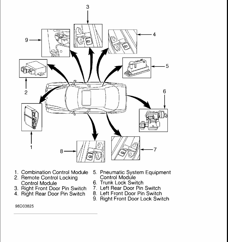
1997-98 ACCESSORIES & EQUIPMENT Anti-Theft Systems - E300, E320, E420, E430 COMPONENT LOCATIONS Refer to illustration for component locations. See Fig. 1 .
Fig. 1: Locating Alarm System Components Courtesy of MERCEDES-BENZ OF NORTH AMERICA PROGRAMMING CONTROL MODULE
Connect HHT to DLC. DLC is located in right rear corner of engine compartment. Menu item No. 5 on HHT allows programming of control modules which require programming. Only upon completion of programming is control module operational. Programming is menu driven. Follow HHT manufacturer's instructions displayed on HHT screen to program control module. No additional information is available from manufacturer at time of publication. FUNCTION TESTS LEFT FRONT DOOR Activate Anti-Theft System Using Left Front Door Open driver's door window. Lock driver's door with key. After about 15 seconds, open left front door from inside. Ensure theft alarm horn sounds and lights flash. Deactivate anti-theft system. If theft alarm horn does not sound and lights do not flash, perform TEST 2 under SYSTEM TESTS. RIGHT FRONT DOOR Activate Anti-Theft System Using Right Front Door Open passenger door window. Lock passenger door with key. After about 15 seconds, open passenger door from inside. Ensure theft alarm horn sounds and lights flash. Deactivate anti-theft system. If theft alarm horn does not sound and lights do not flash, perform TEST 3 under SYSTEM TESTS. LEFT & RIGHT REAR DOOR Activate Anti-Theft System Using Left Or Right Rear Door Open rear door window. Lock passenger door with key. After about 15 seconds, open rear door from inside. Ensure theft alarm horn sounds and lights flash. Deactivate anti-theft system. If theft alarm horn does not sound and lights do not flash, perform TEST 4 and TEST 5 under SYSTEM TESTS. ENGINE HOOD Activate Anti-Theft System Using Hood Open driver's door window. Lock driver's door with key. After about 15 seconds, release hood by reaching through left door open window. Open hood. Ensure theft alarm horn sounds and lights flash. Deactivate anti- NOTE: Hand-Held Tester (HHT) (965 589 00 01 00) is necessary to set control module parameters. CAUTION: When programming control module, avoid interrupting control module voltage supply. Damage to control module may result. DO NOT connect HHT to Data Link Connector (DLC) with ignition on. Damage to HHT may result.
theft system. If theft alarm horn does not sound and lights do not flash, perform TEST 7 under SYSTEM TESTS. TRUNK LID Activate Anti-Theft System Using Trunk Lid Open trunk lid. Lock driver's door with key. Turn off trunk light. After about 15 seconds, turn on trunk light. Ensure theft alarm horn sounds and lights flash. Deactivate anti-theft system. If theft alarm horn does not sound and lights do not flash, perform TEST 6 under SYSTEM TESTS. IGNITION Activate Anti-Theft System Using Ignition Sit in driver's seat. Open driver's door window. Lock vehicle with key from driver's door by reaching through open window. After about 15 seconds, turn ignition switch to ON position. Ensure theft alarm horn sounds and lights flash. Deactivate anti-theft system. If theft alarm horn does not sound and lights do not flash, perform TEST 2 under SYSTEM TESTS. SERVICE BRAKE Activate Anti-Theft System Using Service Brake 1. Sit in driver's seat. Open driver's door window. Lock vehicle with key from driver's door by reaching through open window. After about 15 seconds, turn ignition switch to ON position. Ensure theft alarm horn sounds and lights flash. If theft alarm horn does not sound and lights do not flash, perform TEST 8 under SYSTEM TESTS. 2. Await completion of alarm cycle (about 30 seconds). When cycle ends, step on service brake. Ensure theft alarm horn sounds and lights flash. Deactivate anti-theft system. If theft alarm horn does not sound and lights do not flash, perform TEST 8 under SYSTEM TESTS. RADIO Activate Anti-Theft System Using Radio Sit in driver's seat. Open driver's door window. Lock vehicle with key from driver's door by reaching through open window. After about 15 seconds, remove radio. Ensure theft alarm horn sounds and lights flash. Deactivate anti-theft alarm. If theft alarm horn does not sound and lights do not flash, perform TEST 9 under SYSTEM TESTS. Check anti-theft connector for poor connection at radio. Repair as necessary. ANTI-THEFT STATUS INDICATOR LIGHT NOTE: Obtain radio code from customer before proceeding with this procedure. After radio function test is performed, radio must be recoded.
Lock vehicle, then wait about 15 seconds. Ensure LED in center console blinks. If LED does not blink, perform TEST 13 under SYSTEM TESTS. SELF-DIAGNOSTIC SYSTEM RETRIEVING & CLEARING CODES DTC IDENTIFICATION NOTE: Codes may be retrieved by connecting Hand-Held Tester (965 589 00 01 00) and Adapter Harness (965 589 00 40 00) to Data Link Connector (DLC). Follow HHT manufacturer's instructions to retrieve codes. No other information is available from manufacturer at time of publication. After codes have been retrieved, see DTC IDENTIFICATION table for description of cause of code, then perform appropriate test in SYSTEM TESTS . Code Cause B1021 (1) CAN Data Line B1024 (2) CAN Data Line B1025 (3) CAN Data Line B1220 (4) Absence Of Equipment B1221 (4) Absence Of Equipment B1710 (5) Trunk Light Switch Circuit B1711 (6) Engine Hood Switch Circuit B1712 (7) Left Front Door Alarm Circuit B1713 (8) Right Front Door Alarm Circuit B1714 (9) Left Rear Door Alarm Circuit B1715 (10) Right Rear Door Alarm Circuit B1718 (11) Radio Circuit B1719 (4) Absence Of Equipment B1720 (4) Absence Of Equipment B1721 (7) Ignition System Circuit B1722 (12) Stoplight Circuit B1723 (4) Absence Of Equipment B1724 (4) Absence Of Equipment B1725 (4) Absence Of Equipment B1726 (13) Circuit No. 30 Interrupted While In Armed State B1727 (4) Absence Of Equipment
SYSTEM TESTS TEST PREPARATION Ensure battery voltage is 11-14 volts. Ensure all fuses are okay. Ensure central locking system, infrared central (remote) locking system, parking lights, headlights and brakelights are operating properly. Prior to performing system tests, connect Harness Adapter (202 589 04 63 00) and Breakout Box (124 589 00 21 00) to Pneumatic System Equipment (PSE) control module. TEST 1: VOLTAGE SUPPLY TO PSE CONTROL MODULE 1. Disconnect Pneumatic System Equipment (PSE) control module harness connectors. Connect harness adapter and breakout box to Pneumatic System Equipment (PSE) control module and harness connectors. Measure voltage between terminal No. 1 at PSE control module harness connector No. 2 and terminal No. 3 at PSE control module harness connector No. 2. If battery voltage exists, go to next step. If battery voltage does not exist, repair wiring. See WIRING DIAGRAMS . 2. Measure voltage between terminals No. 2 and 3 at PSE control module harness connector No. 2. If battery B1728 (4) Absence Of Equipment B1729 (14) Voltage Supply To PSE Control Module (1) Controller Area Network (CAN) data line. Ensure remote locking system, rear window heating system and interior lights work properly. Diagnose and repair as necessary. If all systems are okay, perform TEST 14 under SYSTEM TESTS. (2) Controller Area Network (CAN) data line low. Perform TEST 9 and TEST 10 under SYSTEM TESTS. (3) Controller Area Network (CAN) data high. Perform TEST 9 and TEST 10 under SYSTEM TESTS. (4) Normal for USA models and does not indicate a failure. (5) Perform TEST 6 under SYSTEM TESTS. (6) Perform TEST 7 under SYSTEM TESTS. (7) Perform TEST 2 under SYSTEM TESTS. (8) Perform TEST 3 under SYSTEM TESTS. (9) Perform TEST 4 under SYSTEM TESTS. (10) Perform TEST 5 under SYSTEM TESTS. (11) Perform TEST 9 under SYSTEM TESTS. (12) Perform TEST 8 under SYSTEM TESTS. (13) Perform TEST 1 under SYSTEM TESTS. (14) Pneumatic System Equipment (PSE) control module. Do TEST 1 .
voltage exists, replace PSE control module. If battery voltage does not exist, repair wiring. See WIRING DIAGRAMS . TEST 2: LEFT FRONT DOOR ALARM CIRCUIT Disconnect Pneumatic System Equipment (PSE) control module harness connectors. Connect harness adapter and breakout box to Pneumatic System Equipment (PSE) control module and harness connectors. Measure voltage between terminal No. 3 at PSE control module harness connector No. 1 and terminal No. 1 PSE control module harness connector No. 2. When left front door is closed, less than one volt should exist. When left front door is open, battery voltage should exist. If voltage is as specified, replace PSE control module. If voltage is not as specified, check wiring. See WIRING DIAGRAMS . If wiring is okay, replace left front door switch. TEST 3: RIGHT FRONT DOOR ALARM CIRCUIT Disconnect Pneumatic System Equipment (PSE) control module harness connectors. Connect harness adapter and breakout box to Pneumatic System Equipment (PSE) control module and harness connectors. Measure voltage between terminal No. 4 at PSE control module harness connector No. 1 and terminal No. 1 at PSE control module harness connector No. 2. When right front door is closed, less than one volt should exist. When right front door is open, battery voltage should exist. If voltage is as specified, replace PSE control module. If voltage is not as specified, check wiring. See WIRING DIAGRAMS . If wiring is okay, replace right front door switch. TEST 4: LEFT REAR DOOR ALARM CIRCUIT Disconnect Pneumatic System Equipment (PSE) control module harness connectors. Connect harness adapter and breakout box to Pneumatic System Equipment (PSE) control module and harness connectors. Measure voltage between terminal No. 6 at PSE control module harness connector No. 1 and terminal No. 1 at PSE control module harness connector No. 2. When left rear door is closed, less than one volt should exist. When left rear door is open, battery voltage should exist. If voltage is as specified, replace PSE control module. If voltage is not as specified, check wiring. See WIRING DIAGRAMS . If wiring is okay, replace left rear door switch. TEST 5: RIGHT REAR DOOR ALARM CIRCUIT NOTE: Left front door switch can be activated using HHT. Generic scan tool may not be capable of activating left front door switch. NOTE: Right front door switch can be activated using HHT. Generic scan tool may not be capable of activating right front door switch. NOTE: Left rear door switch can be activated using HHT. Generic scan tool may not be capable of activating left rear door switch. NOTE: Right rear door switch can be activated using HHT. Generic scan tool may not be capable of activating right rear door switch.
Disconnect Pneumatic System Equipment (PSE) control module harness connectors. Connect harness adapter and breakout box to Pneumatic System Equipment (PSE) control module and harness connectors. Measure voltage between terminal No. 5 at PSE control module harness connector No. 1 and terminal No. 1 at PSE control module harness connector No. 2. When right rear door is closed, less than one volt should exist. When right rear door is open, battery voltage should exist. If voltage is as specified, replace PSE control module. If voltage is not as specified, check wiring. See WIRING DIAGRAMS . If wiring is okay, replace right rear door switch. TEST 6: TRUNK LIGHT SWITCH CIRCUIT Disconnect Pneumatic System Equipment (PSE) control module harness connectors. Connect harness adapter and breakout box to Pneumatic System Equipment (PSE) control module and harness connectors. Measure voltage between terminal No. 1 at PSE control module harness connector No. 1 and terminal No. 1 at PSE control module harness connector No. 2. When trunk lid is closed, less than one volt should exist. When trunk lid is open, battery voltage should exist. If voltage is as specified, replace PSE control module. If voltage is not as specified, check wiring. See WIRING DIAGRAMS . If wiring is okay, replace trunk lid switch. TEST 7: ENGINE HOOD SWITCH CIRCUIT Disconnect Pneumatic System Equipment (PSE) control module harness connectors. Connect harness adapter and breakout box to Pneumatic System Equipment (PSE) control module and harness connectors. Measure voltage between terminal No. 5 (terminal No. 19 on breakout box) at PSE control module harness connector No. 3 and terminal No. 1 at PSE control module harness connector No. 2. When engine hood is closed, less than one volt should exist. When engine hood is open, battery voltage should exist. If voltage is as specified, replace PSE control module. If voltage is not as specified, check wiring. See WIRING DIAGRAMS . If wiring is okay, replace engine hood switch. TEST 8: STOPLIGHT CIRCUIT Disconnect Pneumatic System Equipment (PSE) control module harness connectors. Connect harness adapter and breakout box to Pneumatic System Equipment (PSE) control module and harness connectors. Measure voltage between terminal No. 12 (terminal No. 26 on breakout box) at PSE control module harness connector No. 3 and terminal No. 3 at PSE control module harness connector No. 2. When brake pedal is released, less than one volt should exist. When brake pedal is depressed, battery voltage should exist. If voltage is as specified, replace PSE control module. If voltage is not as specified, check wiring. See WIRING DIAGRAMS . If wiring is okay, replace stoplight switch. TEST 9: RADIO ALARM CONNECTOR CIRCUIT 1. Disconnect Pneumatic System Equipment (PSE) control module harness connectors. Connect harness NOTE: Trunk light switch can be activated using HHT. Generic scan tool may not be capable of activating trunk light switch. NOTE: Engine hood switch can be activated using HHT. Generic scan tool may not be capable of activating engine hood switch.
adapter and breakout box to Pneumatic System Equipment (PSE) control module and harness connectors. With radio installed and connected correctly, measure voltage between terminal No. 1 at PSE control module harness connector No. 2 and terminal No. 2 (terminal No. 16 at breakout box) at PSE control module harness connector No. 3. Battery voltage should exist. 2. Remove radio. Voltage should be less than one volt. If voltage is as specified, radio alarm connector circuit is okay at this time. If voltage is not as specified, check wiring. See WIRING DIAGRAMS . If wiring is okay, check radio connector and radio ground connection. Repair as necessary. TEST 10: ALARM HORN Disconnect Pneumatic System Equipment (PSE) control module harness connectors. Connect harness adapter and breakout box to Pneumatic System Equipment (PSE) control module and harness connectors. Using a jumper wire, bridge terminal No. 1 at PSE control module harness connector No. 2 and terminal No. 4 at PSE control module harness connector No. 4. Horn should sound. If horn sounds, horn circuit is okay at this time. If horn does not sound, check wiring. See WIRING DIAGRAMS . If wiring is okay, replace alarm horn. TEST 11: HAZARD FLASHER ALARM CIRCUIT 1. Disconnect Pneumatic System Equipment (PSE) control module harness connectors. Connect harness adapter and breakout box to Pneumatic System Equipment (PSE) control module and harness connectors. Using a jumper wire, bridge terminal No. 1 at PSE control module harness connector No. 2 and terminal No. 2 at PSE control module harness connector No. 4. Ensure left hazard flasher illuminates. 2. Using a jumper wire, bridge terminal No. 1 at PSE control module harness connector No. 2 and terminal No. 1 at PSE control module harness connector No. 4. Ensure right hazard flasher illuminates. If hazard flashers illuminate, system is okay at this time. If hazard flashers do not illuminate, check wiring. See WIRING DIAGRAMS . TEST 12: HEADLIGHT ALARM CIRCUIT Disconnect Pneumatic System Equipment (PSE) control module harness connectors. Connect harness adapter and breakout box to Pneumatic System Equipment (PSE) control module and harness connectors. Using a jumper wire, bridge terminal No. 2 at PSE control module harness connector No. 2 and terminal No. 3 at PSE control module harness connector No. 4. Headlights should illuminate. If headlights do not illuminate, check wiring. See WIRING DIAGRAMS . If wiring is okay, check headlight switch. Repair as necessary. NOTE: Alarm horn can be activated using HHT. Generic scan tool may not be capable of activating alarm horn. NOTE: No code is referred to this test. Hazard flasher circuit can be activated using HHT only. Generic scan tool may not be capable of activating hazard flasher circuit. NOTE: No code is referred to this test. Headlight alarm circuit can be activated using HHT only. Generic scan tool may not be capable of activating headlight alarm circuit.
TEST 13: ANTI-THEFT STATUS INDICATOR LIGHT Disconnect Pneumatic System Equipment (PSE) control module harness connectors. Connect harness adapter and breakout box to Pneumatic System Equipment (PSE) control module and harness connectors. Using a jumper wire, bridge terminal No. 1 at PSE control module harness connector No. 2 and terminal No. 16 (terminal No. 30 at breakout box) at PSE control module harness connector No. 3. Ensure indicator light illuminates. If indicator light illuminates, system is okay at this time. If indicator light does not illuminate, check wiring. See WIRING DIAGRAMS . Check anti-theft status indicator light bulb. Replace as necessary. TEST 14: CAN DATA LINE 1. Using Harness Adapter (202 589 15 63 00), connect Breakout Box (124 589 00 21 00) to Pneumatic System Equipment (PSE) control module harness connector, but DO NOT connect breakout box to PSE control module. Disconnect combination control module harness connector. Check resistance between terminal No. 9 at breakout box and terminal No. 62 at combination control module harness connector. If less than one ohm exists, go to next step. If one ohm or greater exists, repair wiring. See WIRING DIAGRAMS . 2. Check resistance between terminal No. 10 at breakout box and terminal No. 78 at combination control module harness connector. If less than one ohm exists, go to next step. If one ohm or greater exists, repair wiring. See WIRING DIAGRAMS . 3. Disconnect negative battery cable. Check resistance between terminal No. 9 at breakout box and terminal No. 1 at PSE control module connector No. 2. If greater than 20 k/ohms exists, go to next step. If 20 k/ohms or less exists, repair wiring. See WIRING DIAGRAMS . 4. Check resistance between terminal No. 10 at breakout box and terminal No. 1 at PSE control module connector No. 2. If greater than 20 k/ohms exists, go to next step. If 20 k/ohms or less exists, repair wiring. See WIRING DIAGRAMS . 5. Connect negative battery cable. Check resistance between terminal No. 9 at breakout box and terminal No. 3 at PSE control module connector No. 2. If greater than 20 k/ohms exists, go to next step. If 20 k/ohms or less exists, repair wiring. See WIRING DIAGRAMS . 6. Check resistance between terminal No. 10 at breakout box and terminal No. 3 at PSE control module connector No. 2. If greater than 20 k/ohms exists, go to next step. If 20 k/ohms or less exists, repair wiring. See WIRING DIAGRAMS . 7. Check resistance between terminals No. 9 and 10 at breakout box. If greater than 20 k/ohms exists, wiring is okay at this time. If 20 k/ohms or less exists, repair wiring. See WIRING DIAGRAMS . REMOVAL & INSTALLATION WIRING DIAGRAMS NOTE: No code is referred to this test. Indicator light can be activated using HHT only. Generic scan tool may not be capable of activating indicator light. NOTE: Removal and installation procedures are not available from manufacturer at time of publication.
Our informative shop, service, repair manual, owner's manuals, and parts catalogs contain all the information you'll need to perform repairs, look up parts, or do routine maintenance on your machine. The manuals include topics such as:
General Information
Routine Maintenance
Engine Removal and Installation
Fuel System
Lubrication and Cooling System
Engine Specifications
Transmission, Drive Chain & Sprockets
Steering System
Shocks
Body Work
Intake & Exhaust
Electrical System
Advanced Troubleshooting
With our manuals, find the page pertaining to your job, print it off, and get working on your project. No more ruining your expensive paper shop manual with grease and dirt.
Broken down on the trail or site and have a smartphone? What a cool way to find your problem and fix it, no downtime on the job site. With our manuals, you instantly have access to the material needed to get you running again.
Our entire manual collection comes with a lifetime protection policy. If lost or damaged, simply contact us, and we'll replace it free of charge for life.
We provide various service manuals, workshop manuals, repair manuals, owner's manuals, parts catalogs, and other various manuals, all in an electronic format.
Manuals cover UTVs, motorcycles, ATVs, quads, snowmobiles, Seadoo, equipment, small engines, inboards, outboards, and more.
Instant access with no shipping cost. Get a manual now and repair it without waiting.
If you are looking for a specific manual and cannot find it or do not see it listed, then contact our customer support team via the contact us link above with details of the required manual, and we will do our absolute best to find and list it for you. Instant access after payment. Thank you.