3.2L 6-CYL VINS [S,T]
Article Text
1996 Mercedes-Benz E320
For 1
Copyright © 1998 Mitchell Repair Information Company, LLC
Wednesday, December 01, 2010 01:59AM
ARTICLE BEGINNING
1995-96 ENGINES
Mercedes-Benz - 3.2L 6-Cylinder
E320
* PLEASE READ THIS FIRST *
NOTE: For repair procedures not covered in this article, see
ENGINE OVERHAUL - GENERAL INFORMATION article in GENERAL
INFORMATION section.
ENGINE IDENTIFICATION
The engine family designation is shown on the emission
control information plate (attached to radiator crossmember). The
first character identifies the model year ("S" for 1995, "T" for 1996)
while the fourth and fifth characters identify the engine
displacement.
ENGINE IDENTIFICATION CODES TABLE
Application & (1) Engine Engine
Engine Size ID Code
1995 ................... 104.992 .......... SMB3.6VJGFFA
1996 ................... 104.995 .......... TMB3.6VJGFFA
(1) - The engine identification number must be used when
ordering replacement parts.
ADJUSTMENTS
VALVE CLEARANCE ADJUSTMENT
Hydraulic valve lifters are used, and valve clearance
adjustment is not necessary.
REMOVAL & INSTALLATION
FUEL PRESSURE RELEASE
Disconnect fuel pump connector. Start engine. Allow engine to
run until it stalls. Turn ignition off. Reconnect fuel pump connector.
NOTE: For reassembly reference, label all electrical connectors,
vacuum hoses and fuel lines before removal.
3.2L 6-CYL VINS [S,T] Article Text (p. 2)
1996 Mercedes-Benz E320For 1
Copyright © 1998 Mitchell Repair Informatio
ENGINE
Removal & Installation
1) Release fuel pressure. See FUEL PRESSURE RELEASE. Raise
hood to vertical position and secure. Obtain radio anti-theft code.
Remove small access panel located below right rear seat. Disconnect
negative battery cable located behind access panel.
2) Remove engine undercover. Remove air cleaner assembly.
Remove viscous fan assembly. Drain cooling system. Remove radiator.
Attach a guard plate to A/C condenser.
3) Disconnect control module connectors located in right rear
corner of engine compartment. Disconnect 3 electrical connectors
located under Hot Film Engine Management Sequential Fuel Injection
(HFM-SFI) engine control module connector. Disconnect cable and
bracket located in engine compartment located outside driver's
footwell area.
4) Remove windshield washer reservoir. Disconnect electrical
connector located in left rear corner of engine compartment attached
to fenderwell.
5) Disconnect power steering pump interference suppression
ground connection located on left fenderwell near power steering pump.
Disconnect A/C compressor electrical connector.
6) Disconnect generator wiring. Disconnect ground connection
located at left rear bottom corner of engine (next to transmission).
7) Disconnect mass air sensor connector. Disconnect vacuum
line at brake servo unit. Disconnect all other vacuum line connections
as necessary. Disconnect fuel supply and return lines at fuel
distributor. Disconnect accelerator cable assembly.
8) Remove power steering pump reservoir fluid. Disconnect
power steering pump hydraulic lines at power steering pump. Placing
wrench on tensioning pulley nut, swivel tensioning pulley clockwise.
9) Remove serpentine accessory drive belt. Slowly release
tension at tensioning pulley. Disconnect coolant hose located at left
rear corner of engine compartment.
10) Unbolt A/C compressor and set aside with A/C hoses
attached to compressor. Disconnect exhaust system at exhaust manifold
flange. Attach a hose to coolant drain located on right side of engine
block, behind engine mount. Open coolant drain, and drain coolant from
engine block.
11) Disconnect drive shaft from transmission. Remove 2 bolts
attaching rear engine carrier to rear of transmission. Using a jack,
support rear engine/transmission assembly.
12) Remove 4 bolts attaching rear engine support to vehicle
chassis. Disconnect transmission shift rod. Disconnect front engine
mounts from vehicle body. Remove cover located at top front of engine.
Remove automatic transmission dipstick.
13) Attach hoist to lifting lugs of engine. Ensure all
necessary electrical connections, hoses, linkages and vacuum lines are
disconnected from engine and transmission. Remove engine and
transmission as an assembly. To install, reverse removal procedure.
Adjust all fluid levels.
3.2L 6-CYL VINS [S,T] Article Text (p. 3)
1996 Mercedes-Benz E320For 1
Copyright © 1998 Mitchell Repair Informatio
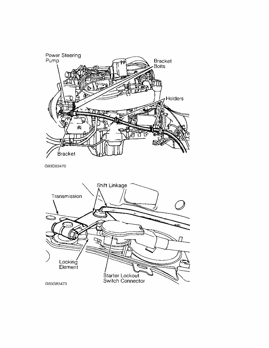
Fig. 1: Identifying Hydraulic Line Bracket Bolts & Holders
Courtesy of Mercedes-Benz of North America.
Fig. 2: Identifying Starter Lockout Switch Connector Locking Element
Courtesy of Mercedes-Benz of North America.
INTAKE MANIFOLD
NOTE: All models are equipped with a 2-piece variable resonance
intake manifold.
3.2L 6-CYL VINS [S,T] Article Text (p. 4)
1996 Mercedes-Benz E320For 1
Copyright © 1998 Mitchell Repair Informatio
Removal & Installation
1) Release fuel pressure. See FUEL PRESSURE RELEASE. With
hood open, press locking lever on left hood hinge. Raise hood slightly
until locking lever does not engage. Press locking lever on right hood
hinge. Raise hood to vertical position. Ensure hood is secure in
vertical position.
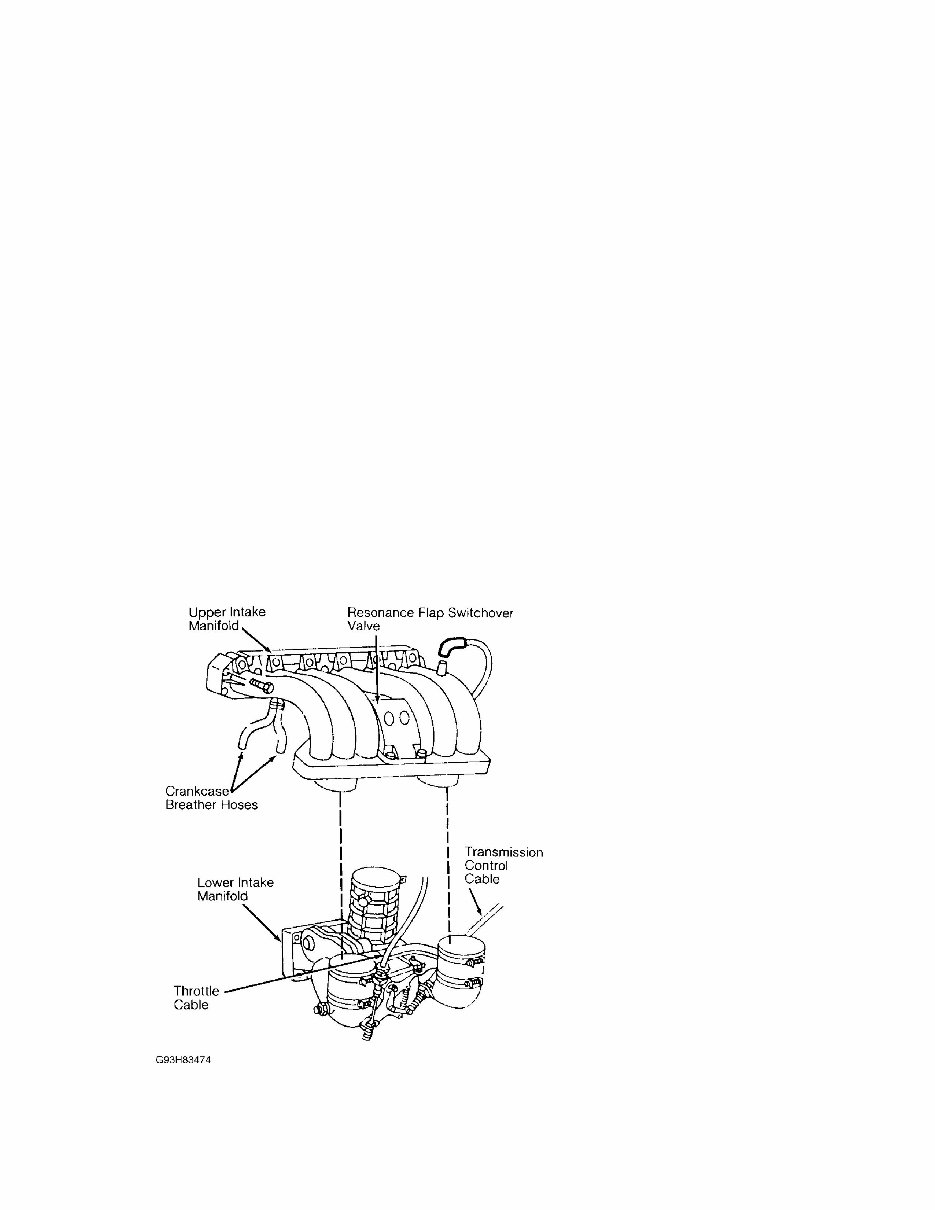
2) Disconnect negative battery terminal. Disconnect crankcase
breather hoses. Disconnect vacuum line located on top rear of upper
intake manifold. Disconnect resonance flap switchover valve electrical
connector. See Fig. 3.
3) Remove bolts for upper intake manifold. Remove dipstick
tube bracket. Loosen top hose clamps connecting lower intake manifold
to upper intake manifold. Remove upper intake manifold. See Fig. 3. If
necessary to remove lower intake manifold, go to next step.
4) Remove guide piece from fulcrum lever for throttle cable.
Compress plastic clip in throttle cable bracket. Remove throttle
cable. Disconnect transmission control cable. Disconnect EGR line.
5) Ensure all necessary electrical and vacuum line
connections are disconnected from lower intake manifold assembly.
Remove lower intake manifold attaching bolts. Remove lower intake
manifold from engine. See Fig. 3. To install, reverse removal
procedure.
Fig. 3: Identifying Upper & Lower Intake Manifold Assemblies
Courtesy of Mercedes-Benz of North America.
EXHAUST MANIFOLD
3.2L 6-CYL VINS [S,T] Article Text (p. 5)
1996 Mercedes-Benz E320For 1
Copyright © 1998 Mitchell Repair Informatio
Removal & Installation
Disconnect negative battery cable. Remove exhaust pipe-to-
manifold nuts. Disconnect exhaust support at transmission. Remove nuts
attaching exhaust manifold to engine. Remove exhaust manifold. To
install, reverse removal procedure.
IGNITION COILS
Removal & Installation
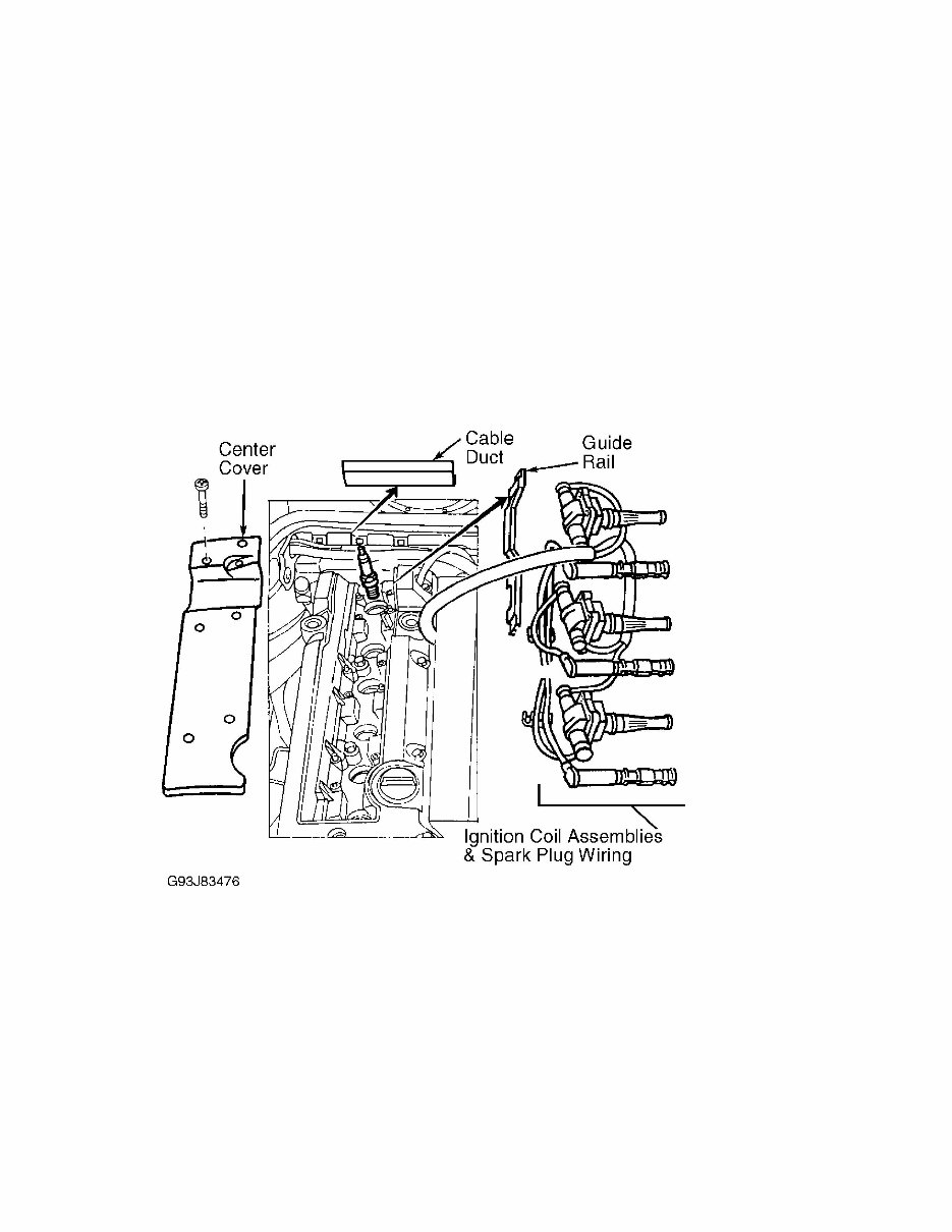
Unclip cable duct at rear of engine. Remove center cover from
valve cover. Remove guide rail. Remove ignition coil assemblies and
spark plug wiring. See Fig. 4. To install, reverse removal procedure.
Fig. 4: Removing & Installing Ignition Coils
Courtesy of Mercedes-Benz of North America.
CYLINDER HEAD
Removal
1) Release fuel pressure. See FUEL PRESSURE RELEASE. With
hood open, press locking lever on left hood hinge. Raise hood slightly
until locking lever does not engage. Press locking lever on right hood
hinge. Raise hood to vertical position. Ensure hood is secure in
vertical position.
2) Disconnect negative battery terminal. Remove shield under
vehicle covering engine. Drain coolant. Disconnect coolant and heater
hoses at cylinder head. Position crankshaft so No. 1 cylinder is at
TDC. Remove ignition coils. See IGNITION COILS. Remove valve cover.
You're Reading a Preview
What's Included?
Lifetime Access
Access Contents & Bookmarks
Print one or all pages of your manual