2008 MERCEDES CLC-Class Sport COUPE Service & Repair Manual
What's Included?
Lifetime Access
Fast Download Speeds
Online & Offline Access
Access PDF Contents & Bookmarks
Full Search Facility
Print one or all pages of your manual
MERCEDES SERVICE AND REPAIR MANUAL SPORTS COUPE 2001-2008
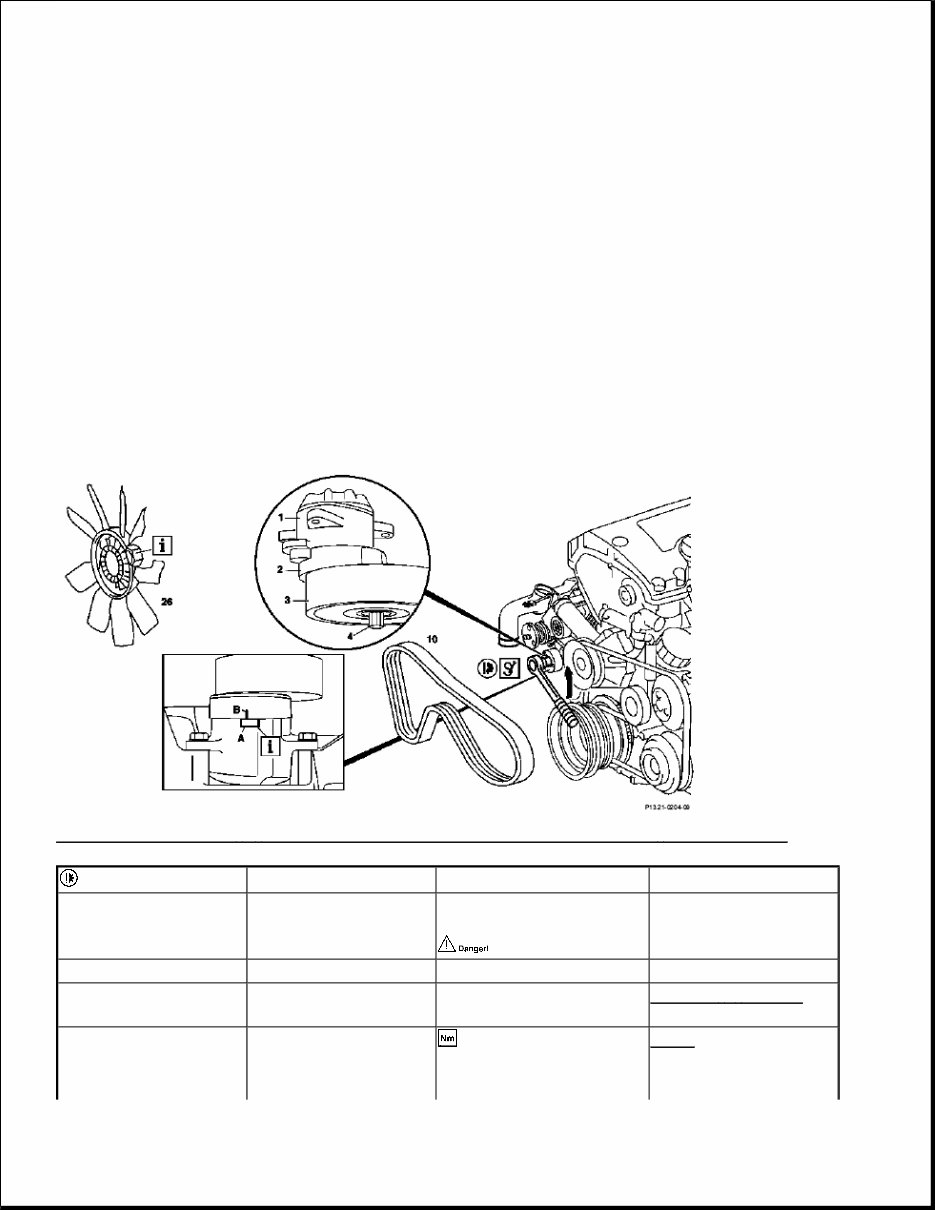
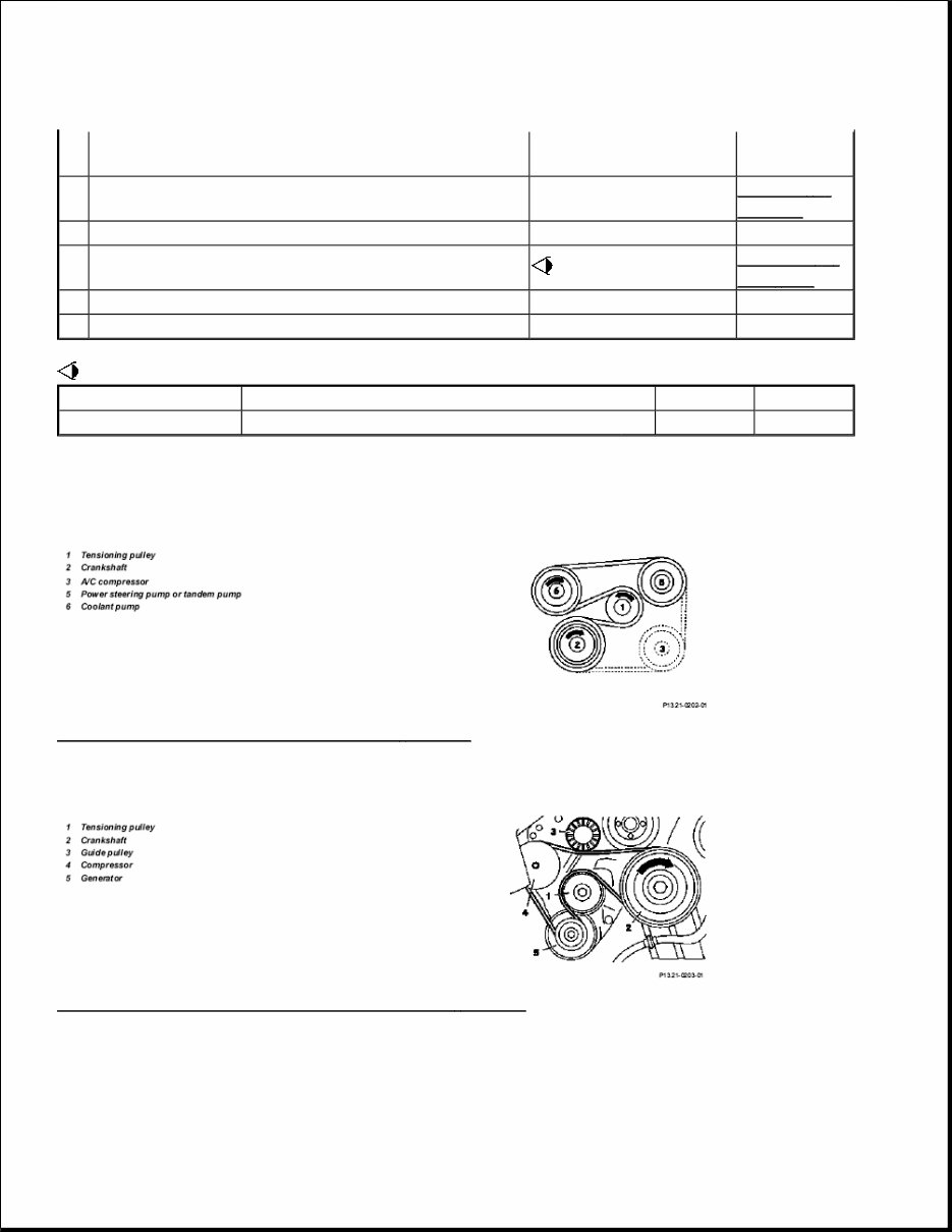
2001-2008 HVAC Air Compressor, Belt Drives - 203 Chassis TESTING & REPAIR REMOVE/INSTALL POLY-V-BELT FOR COMPRESSOR - AR13.21-P-1202A ENGINE 111.943 /973 in MODEL 170 ENGINE 111.944 /975 in MODEL 202, 208 ENGINE 111.947 in MODEL 210 ENGINE 111.955 in MODEL 203 Fig. 1: Identifying Poly - V - Belt For Compressor Remove/Install Components - Engine 111.955 Removing 1 Remove viscous fan clutch (26) Vehicles fitted with viscous fan clutch Left-hand thread AR20.40-P-5660A 2.1 Remove fan shroud Vehicles with fan cowl AR20.40-P-6800HA 2.2 Remove electric fan Vehicles fitted with electric fan AR20.40 - P - 5000PR 3 Loosen poly-V-belt (10) Swivel tensioning arm (2) and tensioning pulley (3) in counterclockwise Fig. 2
MULTI-BELT DRIVE direction at stud bolt (4, external Torx E10) for this step. Do not swivel tensioning arm (2) against tensioning pulley the nut. 4 Remove poly-V-belt (10) Checking 5 Inspect belt pulley sections and tensioning device for damage and dirt. 6 Check poly-V-belt (10) Check poly-V-belt in visible area for wear AP13.22-P-1352Z Install 7 Fit on poly-V-belt (10), then clamp Do not use belt wax or any similar products. In numerical order of relevant running diagram, beginning at tensioning pulley ? Routing diagram of poly-V- belt AR13.21 - P - 3902 - 02A Poly-V-belt dimensions *BE13.21-P-1001-01A The position marking (B) visible from the underside of the engine, must be positioned within the working range (A). If this is not the case, inspect length of poly-V-belt and also tensioning device Fig. 2 8.1 Install fan shroud Vehicles with fan cowl AR20.40-P-6800HA 8.2 Install electric fan Vehicles fitted with electric fan AR20.40 - P - 5000PR 9 Install viscous fan clutch (26) Vehicles fitted with viscous fan clutch Left-hand thread AR20.40-P-5660A Number Designation Engine Engine Engine
MULTI-BELT DRIVE Fig. 2: Identifying External Torx Set (001 589 76 09 00) REMOVE, INSTALL POLY-V-BELT FOR COMPRESSOR - AR13.21-P-1202PK ENGINE 111.955 in MODEL 203.045 /245 /745 111.943/944/947/973/975 without AC compressor with power steering pump 111.944/947/975 without AC compressor with tandem pump 111.943/944/947 973/975 with AC compressor with power steering pump BE13.21- P-1001- 01A Length of belt of compressor drive mm 1330 1330 1330 Number Designation Engine 111.944/947/975 with AC compressor with tandem pump Engine 111.955 with AC compressor with power steering pump BE13.21-P-1001- 01A Length of belt on compressor drive mm 1330 1355
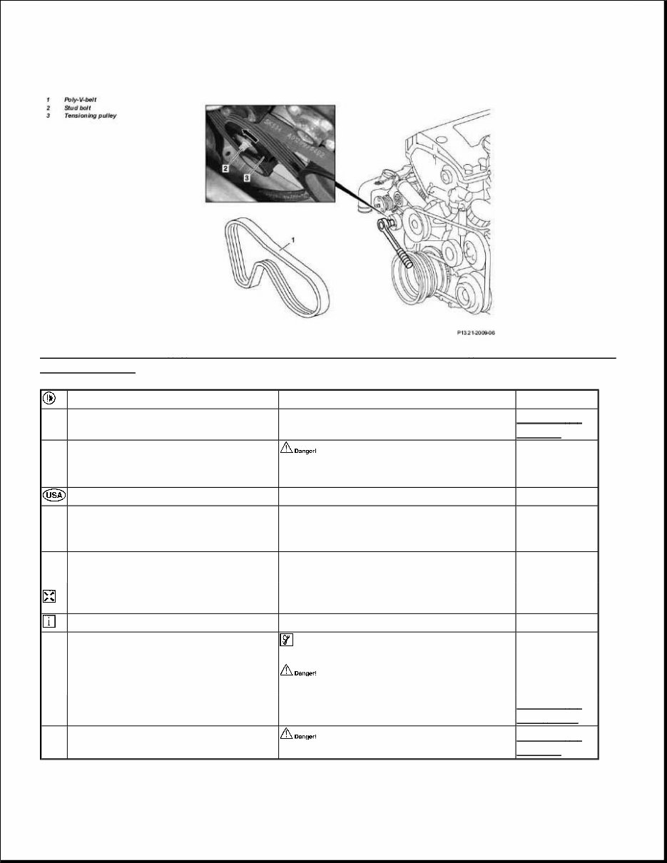
Fig. 3: Identifying Poly - V - Belt For Compressor Remove/Install Components - Engine 111.955 In Model 203.045 /245 /745 Remove 1 Remove air filter housing AR09.10 - P - 1150PK 2 Loosen poly-V-belt (1) and remove Swivel stud bolt (2) at tensioning pulley (3) in anti-clockwise direction (arrow) for this step. Checking 3 Inspect belt pulley sections and tensioning device for damage and dirt, replace if necessary 4 Inspect poly V-belt (1), replace if necessary Check poly-V-belt in visible area for wear AP13.22-P- 1352Z Install 5 Fit on poly V-belt (1), tension Installation: Do not use any belt wax or similar products Fit on poly V-belt as specified in running diagram ? Running diagram of poly V-belt. AR13.22 - P - 3902 - 02PR 6 Install air filter housing Installation: Lightly coat rubber retainer with antifriction agent. AR09.10 - P - 1150PK
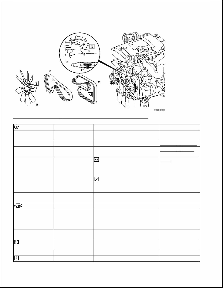
REMOVE/INSTALL POLY-V-BELT GUIDE PULLEY - AR13.21-P-3350QB ENGINE 272.920 in MODELS 203.052 /252 /752 ENGINE 272.940 in MODELS 203.054 /254, 209.354 /454 ENGINE 272.960 in MODELS 203.056 /256 /756, 209.356 /456 ENGINE 272.970 in MODELS 203.087 /287 ENGINE 272.941 in MODELS 203.092 /292 ENGINE 273 in MODEL 209 Fig. 4: Identifying Poly - V - Belt Guide Pulley Remove/Install Components Remove/install Risk of injury caused by fingers being pinched or crushed when removing, installing or aligning hoods, doors, trunk lids, tailgates or sliding roof. Keep body parts and limbs well clear of moving parts. AS00.00 - Z - 0011 - 01A Notes on self-locking nuts and bolts AH00.00 - N - 0001 - 01A 1 Open engine hood and raise to vertical position Model 203 AR88.40 - P - 1000P Model 209 AR88.40-P- 1000Q Pull front engine
COOLANT PUMP, COOLANT THERMOSTAT POLY V-BELT RUNNING DIAGRAM, MULTI-BELT DRIVE - AR13.21-P-3902-02A Running diagram of basic drive (6-groove) Fig. 5: Running Diagram Of Basic Drive (6 - Groove) Running diagram of compressor drive (6-groove) Fig. 6: Running Diagram Of Compressor Drive (6 - Groove) REMOVE/INSTALL POLY V-BELT - AR13.22-P-1202A ENGINE 111 2 Remove front engine cover cover upward and out of mountings. 3 Remove poly-V-belt AR13.22 - P - 1202QB 4 Lever off covers (1b, 2b) 5 Remove bolts (1a, 2a) *BA20.10 - P - 1004 - 01U 6 Remove guide pulleys (1, 2) 7 Install in the reverse order Number Designation Engine 272 Engine 273 BA20.10-P-1004-01U Bolt, poly-V-belt guide pulley at coolant pump Nm 35 35
Fig. 7: Identifying Poly V - Belt Remove/Install Components (Engine 111) Removing 1.1 Remove viscous fan clutch (26) Engines with viscous fan clutch 0046 Left-hand thread AR20.40-P-5660A 1.2 Remove electric fan Engines fitted with electric fan AR20.40 - P - 5000PR 2 Remove poly V-belt of compressor (10) Engine 111 with compressor AR13.21 - P - 1202A 3 Loosen poly-V-belt (11) Swivel tensioning arm (2) and tensioning pulley (3) in counter- clockwise direction at stud bolt (4, external torx E10) for this step. Do not swivel tensioning arm (2) against the nut attaching the tensioning pulley. Fig. 2 4 Take off poly V-belt (11) Checking 5 Inspect belt pulley sections and tensioning device for damage and dirt. 6 Inspect poly V-belt (11) Check poly-V-belt in visible area for wear Except engine 111.977 AP13.22-P-1352Z Engine 111.977 AP13.22-P-1351GH Install
MULTI-BELT DRIVE MULTI-BELT DRIVE 7 Fit on poly-V-belt (11), then clamp Do not use belt wax or similar products. In numerical order of relevant running diagram, beginning at tensioning pulley ? Running diagram of poly V-belt of engines not fitted with compressor AR13.22 - P - 3902 - 02A Running diagram of poly V-belt of engines fitted with compressor AR13.21 - P - 3902 - 02A Poly V-belt dimensions of engines not fitted with compressor *BE13.22 - P - 1001 - 01B Poly V-belt dimensions of engines fitted with compressor *BE13.21 - P - 1002 - 01A The position marking (B) must be positioned within the working range (A). If this is not the case, inspect the length of the poly V-belt and also the tensioning device Fig. 2 8 Install poly V-belt of compressor Engine 111.943/944/947/973/975 AR13.21 - P - 1202A 9.1 Install viscous fan clutch (26) Engines with viscous fan clutch Left-hand thread AR20.40-P-5660A 9.2 Install electric fan Engines fitted with electric fan AR20.40 - P - 5000PR Number Designation Engine 111.943/944/947/973/975 without AC compressor with power steering pump Engine 111.943/944/947/973/975 with AC compressor with power steering pump Engine 111.944/944/947 without AC compressor with tandem pump BE13.21- P-1002- 01A Length of belt of base drive mm 1775 1875 1760 Number Designation Engine 111.944/947/975 with AC compressor with tandem pump Engine 111.955 with AC compressor and with power steering pump Engine 111.958/983 BE13.21-P- 1002-01A Length of belt of base drive mm 1860 1860 1870
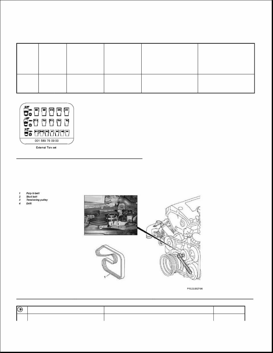
SINGLE-BELT DRIVE Fig. 8: Identifying External Torx Set (001 589 76 09 00) REMOVE/INSTALL POLY V-BELT - AR13.22-P-1202PK ENGINE 111.955 in MODEL 203.045 /245 /745 Fig. 9: Identifying Poly V - Belt Remove/Install Components - Engine 111.955 In Model 203.045 /245 /745 Number Designation Engine 111 except 111.944/947/975 without AC compressor Engine 111 except 111.944/947/975 with AC compressor Engine 111 except 111.943/944/947/973/975 without AC compressor with VDA power steering pump Engine 111 except 111.943/944/947/973/975 with AC compressor with VDA power steering pump BE13.22- P-1001- 01B Belt length mm 2040 2140 2055 2155 Remove AR13.21-P-
Get your hands on the 2008 MERCEDES CLC-CLASS SPORT COUPE SERVICE & REPAIR MANUAL. Whether you're a professional mechanic or a DIY enthusiast, these Auto Repair Manuals provide comprehensive instructions and procedures to help you fix your vehicle. The manuals contain technical data, diagrams, a complete list of car parts, and illustrations, making it easy for even novice car mechanics to follow along. The manual covers various sections including maintenance, engine, control system, mechanical, fuel service specifications, and much more. It is compatible with all versions of Windows and Mac, and is printable for your convenience. With this manual, you can save time and money by learning to repair different parts of your car on your own. Take advantage of the detailed instructions and illustrations to maintain, service, diagnose, and repair your vehicle with ease.
Complete step-by-step instructions, diagrams, and wiring schematics
Comprehensive details on technical data, diagrams, and car parts
Compatible with all versions of Windows and Mac
Printable for convenience
Recently Viewed
5,521,897Happy Clients
2,594,462eManuals
1,120,453Trusted Sellers
15Years in Business
Price:
Actual Price:
2008 MERCEDES CLC-Class Sport COUPE Service & Repair Manual