

1987 Mercedes-Benz 300SDL Service & Repair Manual
What's Included?
Fast Download Speeds
Online & Offline Access
Access PDF Contents & Bookmarks
Full Search Facility
Print one or all pages of your manual
ACCESSORIES & EQUIPMENT
1986-91 Cruise Control
DESCRIPTION
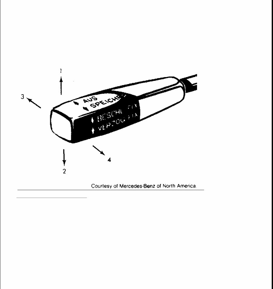
The electronic cruise control system consists of a control unit, electric control motor and a 4-position control
lever. The 4 positions are: "1" - ACCELERATE/SET, "2" - DECELERATE/SET, "3" - CANCEL/OFF and "4"
- RESUME.
Fig. 1: Control Lever Positions
Courtesy of MERCEDES-BENZ OF NORTH AMERICA.
OPERATION
The cruise control will maintain any desired speed above approximately 25 MPH. To set cruise control,
accelerate vehicle to the desired speed. Briefly push the control lever to position "1" or "2". The accelerator may
now be released.
Speed may be increased for passing by using the accelerator. As soon as the accelerator is released, the
previously set speed will be resumed. If the set speed is to be changed, hold lever in position "1" or "2" until the
desired speed is reached. When the lever is released, the new speed will be set. If the brakes are actuated, cruise
control operation is canceled.
COMPONENT FUNCTION
CONTROL UNIT
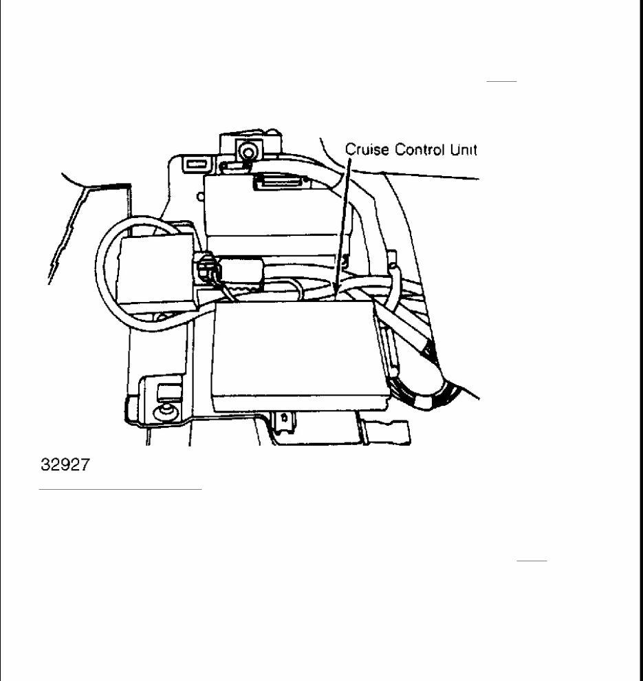
On 260 and 300E models, the control unit is mounted behind passenger footrest. On other models the control
unit is located behind the passenger footrest panel. The control unit compares the actual and the set speed. If the
speeds differ, the control unit activates the control motor to attain the desired speed. See Fig. 2 . The control
unit is fitted with a replaceable reference resistor which allows specifications to differ between the various
models while allowing the same control unit to be utilized.
Fig. 2: Control Unit Mounting
TRANSMITTER
The speed control (Hall Effect) transmitter is located on the back of the speedometer. The speed control
transmitter receives the actual speed signals and sends this information to the control unit. See Fig. 3 .
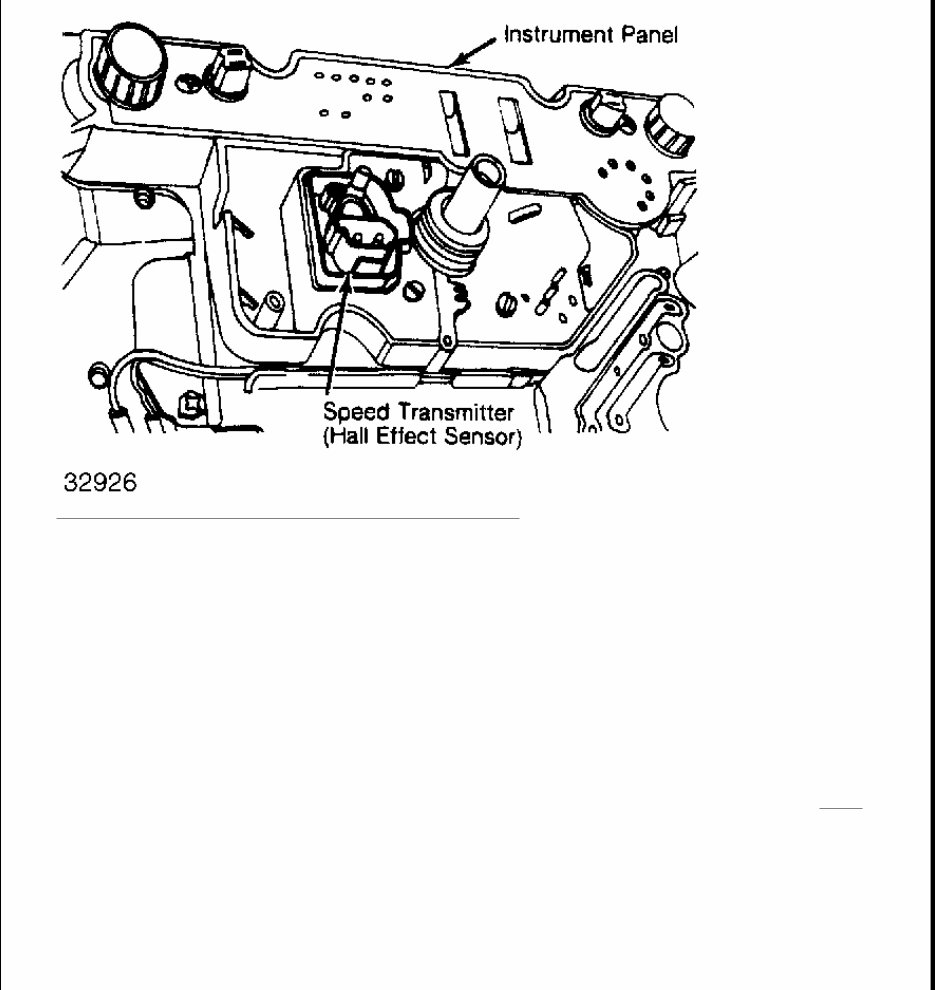
Fig. 3: Location of Speed Control Transmitter (Hall Effect)
ACTUATOR
The actuator receives its control signals from the control unit and actuates the regulating linkage by using a
connecting rod. The actuator is comprised of an electric motor with gear unit, one-way clutch, potentiometer
and a electromagnetic clutch. The actuator output shaft is driven by the electric motor, through a gear reduction
and a one-way clutch.
The one-way clutch permits accelerator pedal use independent of the cruise control actuator. The potentiometer
relays the position of output shaft to the control unit.
The electromagnetic clutch transmits power from the electric motor to the output shaft. The electromagnetic
clutch interrupts shaft movement when the brake or clutch is depressed. Movement is also interrupted when the
system is switched off at the control switch or when the regulating linkage is at idle speed position. See Fig. 4 .
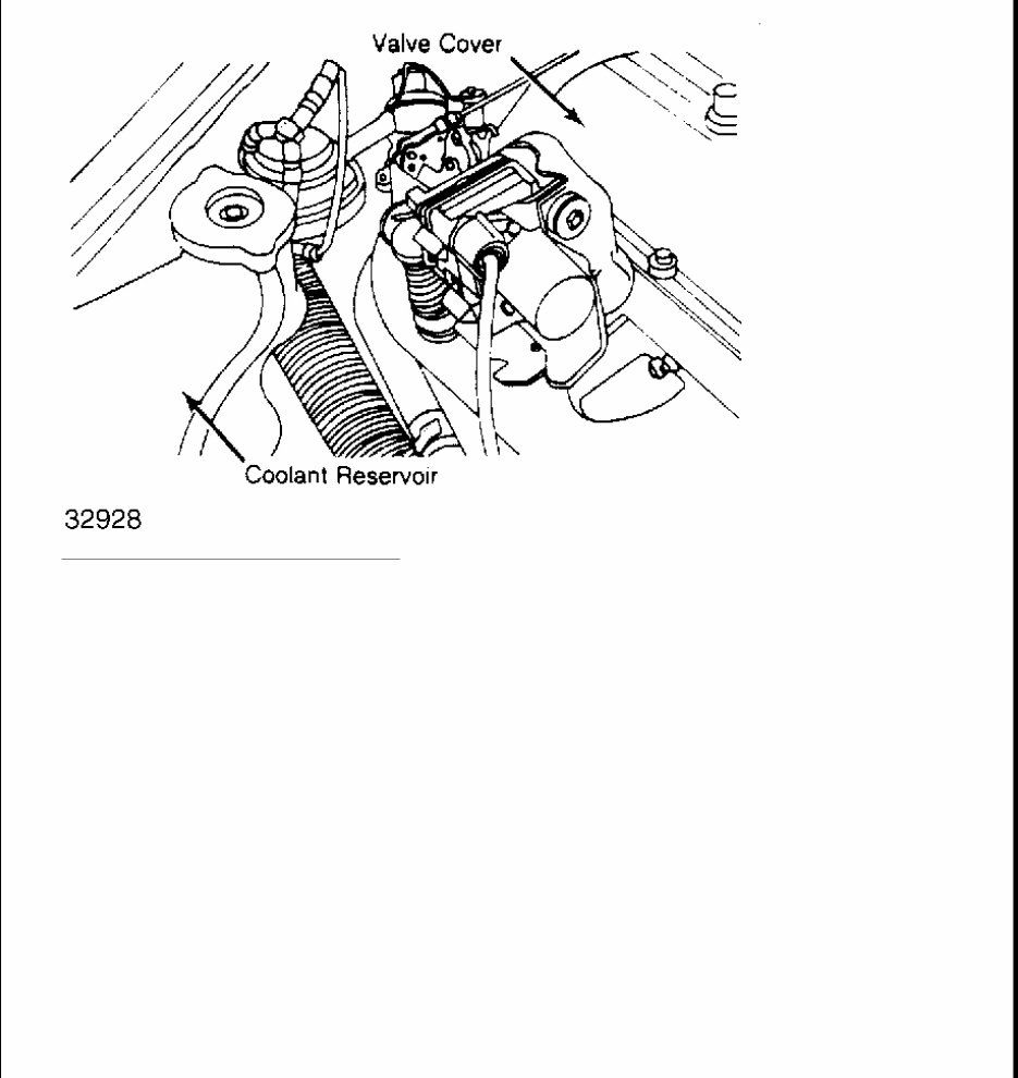
Fig. 4: View of Cruise Control Actuator
CLUTCH PEDAL SWITCHING RELAY
During cruise control operation, the switching relay will shut off the deceleration mode. The relay is painted
Yellow and is located in the main/fuse relay box.
ADJUSTMENTS
ACTUATOR CONNECTING ROD
Adjustment
Disconnect actuator rod at throttle linkage. Ensure throttle linkage is against idle stop. With actuator against idle
stop, adjust actuating rod about .039" (1.0 mm) shorter than length necessary to refit to throttle linkage.
Reconnect actuator rod to throttle linkage.
TROUBLE SHOOTING
CAUTION: When performing work on vehicles equipped with SRS (Supplement
Restraint System), exercise extreme caution when working around
steering wheel or column. DO NOT apply electrical power to any
component on steering column without disconnecting SRS control unit

CRUISE CONTROL INOPERATIVE
Check harness connection at control unit. Test control unit using Test Adapter (126 589 05 21 00).
CRUISE CONTROL SWITCHES OFF BUT CAN BE RESET
Replace control unit.
CRUISE CONTROL WILL ONLY ENGAGE ABOVE 35 MPH
Ensure control unit and reference resistor numbers are correct. Test for continuity at control unit connector,
between pins No. 14 and 12.
OPERATION ERRATIC THROUGH ENTIRE SPEED RANGE
Ensure control unit and reference resistor numbers are correct. Check connection at speed transmitter on back of
speedometer. If connections are correct, replace actuator.
OPERATION ERRATIC WHEN DRIVING DOWNHILL OR ON LEVEL ROAD
Check cruise control harness connections. Disconnect microswitch plug and connect directly to cruise control
harness. Connect remaining cruise control connector to microswitch. Road test vehicle.
ACTUATOR NOISY WHEN IGNITION IS SWITCHED ON
Check connections at actuator and control unit. Ensure contacts are serviceable. Replace actuator if necessary.
THROTTLE PEDAL WILL NOT GO TO FULL POSITION
1. Test actuator and ground connections for continuity. If correct, replace actuator.
2. Ensure that cruise control function is canceled during braking. Push switch "M" on test adapter. Throttle
control and accelerator pedal should move to full position. Depress brake pedal.
3. Throttle control and accelerator pedal should immediately move into idle speed position. If so, testing is
complete. If test is not to specification, check throttle control for ease of operation. If necessary, replace
actuator.
4. On vehicles with manual transmission, test cruise control cutout during clutch operation. Push button "M"
on test adapter. If throttle control and accelerator move to full throttle position, depress clutch pedal. If
throttle control and accelerator pedal are not moving immediately into full throttle position, replace
actuator.
5. Depress brake pedal, if throttle control and accelerator pedal do not move into idle position, replace
actuator. If okay, testing is complete.
TESTING
(air bag system may be activated).

TEST PREPARATION
1. Access control unit and remove 14-pin connector. If factory tester is being used, connect Test Adapter
(126 589 05 21 00) to 14-pin connector. Turn on ignition. The LED symbols for battery and ground
should be on, provided no fault is found.
2. Push LED test button and check that all LED readouts are on. If no LED's are on, test connectors at
voltage supply and cruise control. If correct, replace control unit.
3. If LED lights are on, go to next test. If LED lights are not on, test control switch connector. Replace
control switch, if necessary.
CONNECTOR IDENTIFICATION
FUNCTION CHECKS
Terminal No. 8, of the control unit, must be grounded for cruise control to operate. When the brake pedal is
depressed, the brake switch closes and voltage to the brake lights electrically interrupts the ground circuit to the
control unit, canceling operation. Power is supplied through fuse No. 5 (8-amp) to terminal No. 1 (control unit),
terminal No. 2 (control switch) and terminal No. 1 (speed sensor).
REMOVAL & INSTALLATION
CONTROL UNIT
Removal & Installation
1. Remove floor mat on passenger side. Remove cover for cruise control unit. Pull connector from control
unit. Unscrew control unit from cover and remove from vehicle. On 260 and 300E models the control unit
is mounted under the left side of the dash.
2. To install, reverse removal procedure. Perform road test.
CLUTCH PEDAL SWITCH
Removal & Installation
Remove cover under instrument panel on driver's side. Pull harness from switch. Loosen switch and remove. To
install, reverse removal procedure. Perform road test.
ACTUATOR
Connector Size Location
Actuator 8-Pin Engine Compartment
Speed Sensor 2-Pin Behind Speedometer
Brake Switch 2-Pin Below LH Side Of Dash
Control Switch 5-Pin Below Steering Column
Control Unit 14-Pin At Control unit

Removal
1. Disconnect battery. Separate plug connection. Open cable straps and expose harness at actuator. Remove
ignition distributor cover and distributor finger. Loosen distributor and turn clockwise toward engine and
remove.
2. Disconnect connecting rod on actuator. Remove holder with actuator. Remove holder and lever from
actuator.
Installation
1. To install, reverse removal procedure. Turn output shaft of actuator in opposite direction of arrow against
stop. Refit lever and tighten lock nut.
2. Adjust actuator operating rod. See adjustment procedure in this article. Reset ignition timing. Road test
vehicle.
CONTROL SWITCH
Removal
1. Disconnect battery. Remove cover on driver's side under instrument panel. Pull plug from connector.
Disconnect SRS control unit and CAREFULLY remove steering wheel and jacket tube lining.
2. Disconnect clamps on combination switch. Remove mounting screws together with snap rings. Release
cruise control switch from combination switch and remove.
Installation
To install, reverse removal procedure. Reconnect SRS control unit. Road test vehicle.
WIRING DIAGRAMS
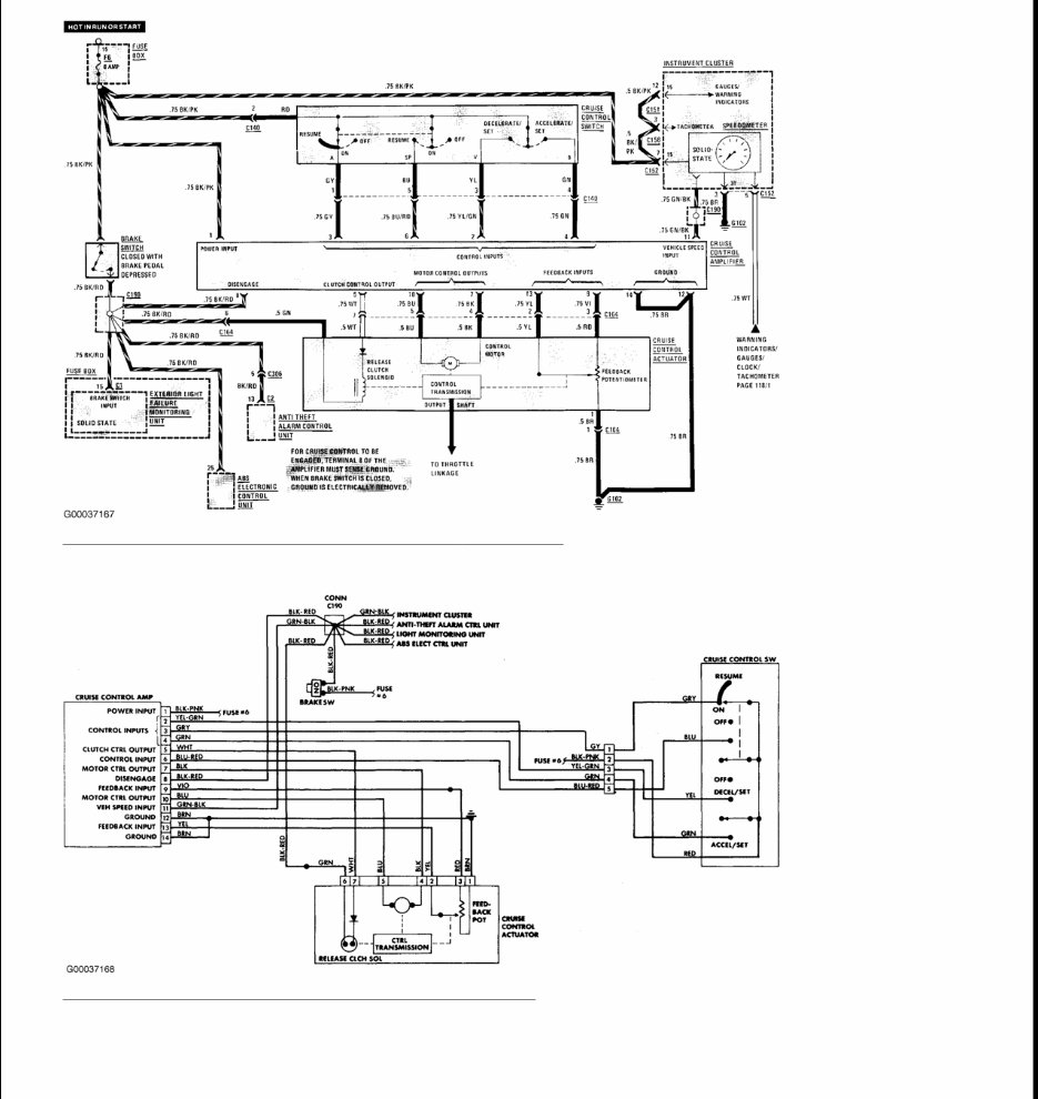
Fig. 5: Cruise Control Wiring Diagram (1986 - 91 420SEL)
Courtesy of MERCEDES-BENZ OF NORTH AMERICA.
Fig. 6: Cruise Control Wiring Diagram (1987 420SEL)
Courtesy of MERCEDES-BENZ OF NORTH AMERICA.

DEFOGGER - REAR WINDOW
1987 Accessories & Safety Equipment ALL MANUFACTURERS DEFOGGERS - REAR WINDOW
DESCRIPTION
Rear window defogger systems use a heating wire grid bonded to the inside of rear window. Window heat is
regulated by a control switch and a relay/timer. An indicator lamp should light to show system is operating.
Power to the control switch is through a fuse in the fuse block.
OPERATION
Defogger operates when the ignition is on and control switch is moved to "ON" position. When the switch is
turned to the "ON" position, current flows through the wire and evaporates the water from the window. The
timer relay will keep power to the grid for a few minutes or until the ignition is turned off.
TROUBLE SHOOTING
DEFOGGER DOES NOT WORK
Blown fuse or poor contact. Defogger switch defective. Poor connections. Broken wire. Relay defective.
INDICATOR LIGHT DOES NOT WORK
Bulb burned out. Open wire or poor connection.
TESTING
SYSTEM TESTING
1. Check that all in-line fuses or circuit breakers are operational. Turn ignition and control switches to "ON"
position. Check rear window glass temperature after a few minutes. Glass should feel warm to the touch.
2. If glass is not warm, use a test light or voltmeter to check for battery voltage at grid feed wire. If voltage
is not correct, check wiring harness, control switch and timer/relay.
FILAMENT TESTING
1. To locate breaks in grid wire filaments, attach a voltmeter to middle portion of each filament. Attach
other meter probe to vertical section of window grid.
2. If a grid is broken, meter will register zero volts or battery voltage, depending on if grid is broken
between or outside test leads. If wire is unbroken, meter will register about one half of battery voltage. To
locate break, move probe along wire until the meter needle moves abruptly.
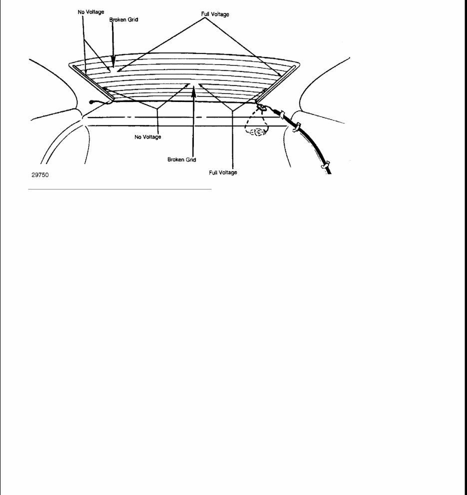
Fig. 1: Voltage Test for Broken Grid Filaments
You're Reading a Preview
What's Included?
Fast Download Speeds
Online & Offline Access
Access PDF Contents & Bookmarks
Full Search Facility
Print one or all pages of your manual
$31.99
Viewed 87 Times Today


Secure transaction
What's Included?
Fast Download Speeds
Online & Offline Access
Access PDF Contents & Bookmarks
Full Search Facility
Print one or all pages of your manual
$31.99
- The 1987 Mercedes-Benz 300SDL Service & Repair Manual is a comprehensive resource for fixing vehicle issues, suitable for both professional mechanics and DIY enthusiasts.
- It includes troubleshooting and replacement procedures recommended by the manufacturer, featuring step-by-step instructions, clear images, and exploded-view illustrations.
- Regular maintenance is essential for the durability of your vehicle, and this manual provides the necessary guidance for addressing wear and tear over time.
- With the manufacturer's recommended troubleshooting charts and replacement procedures, this manual enables cost-effective repairs, enhances vehicle reliability, and reduces reliance on repair shops.
- Convenient digital format eliminates the hassle of flipping through pages, ensuring easy access, searchability, and portability on various electronic devices.
- Additionally, the manual is printable and compatible with a wide range of electronic devices, including PC, Mac, Android, and Apple devices, requiring only Adobe Reader (free) for access.


