03 Crankshaft assembly Job No. Checking, replacing and tightening connecting rod bolts .......................... 03 - 310 Reconditioning and squaring connecting rods .................................. 03 - 313 Removal and installation of pistons .......................................... - 316 Modifications to pistons .................................................. -317 Checking and reconditioning crankshaft ....................................... - 318 Installation of crankshaft and connecting rod bearings ............................. - 320 Modifications to crankshaft ................................................ - 321 Replacing front crankshaft radial sealing ring ................................... - 324 Removal and installation of pilot bearing in crankshaft ............................. - 330 Removal and installation of crankshaft pulley and hub ............................. - 341 Checking and correcting adjustment of TDC sensor .............................. - 345 Removal and installation of crankshaft sprocket ................................. - 350 Removal and installation of flywheel and driven plate ............................. - 410 Refinishing flywheel ..................................................... - 420 Replacing ring gear ..................................................... - 430 0311
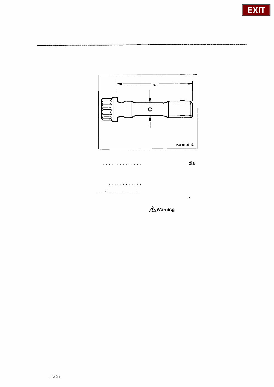
03-310 Checking, replacing and tightening connecting rod bolts P03-0100-13 Stretch bolt dia. (dimension c) . . . . . . . . . . . . . . measure, minimum dia, If shaft dia. is less than connecting rod bolts. Threads on connecting rod bolts , . . . . . . . . . , . oil. = 7.1 mm. 7.1 mm replace Connecting rod bolts . . . . . . . . . . . . . . . . . . . . . initially tighten to 30 Nm and then tighten to rotation angle of 90 - 100”. AWarning Do not use torque wrench with flexible shaft for rotation angle tightening. Note Estimate angle of rotation. For this purpose insert adjustable torque wrench in break position (locked) into ratchet. Position adjustable torque wrench with plug-in ratchet lengthwise in relation to engine and continue to turn until it is transverse in relation to engine. 03.10 - 310/l
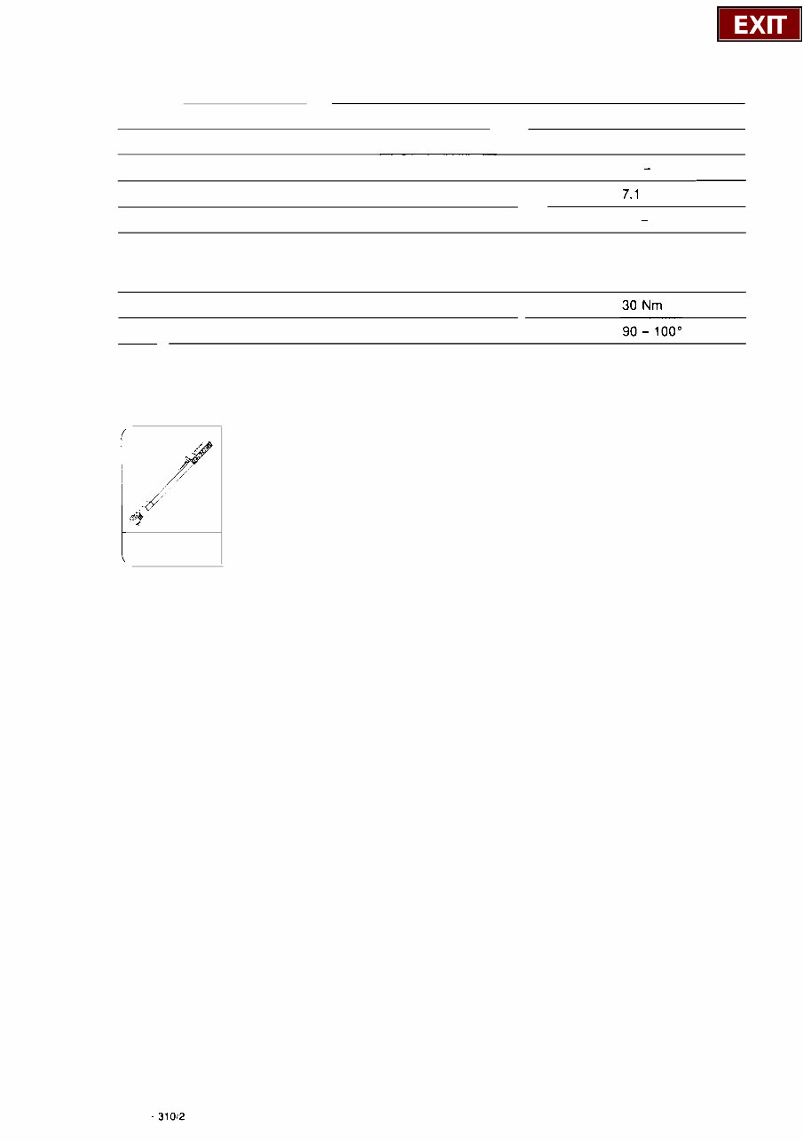
Dimensions Part No. 102 038 00 71 Thread M 9x1 Necked down shaft dia. (c) in new condition 7.4 - 0.1 Minimum necked down shaft dia. (c) Length (L) in new condition 52 - 0.3 Tightening torques and rotation angles Initial tightening torque Rotation angle Special tool 001 589 72 21 00 00 03.10 - 31012
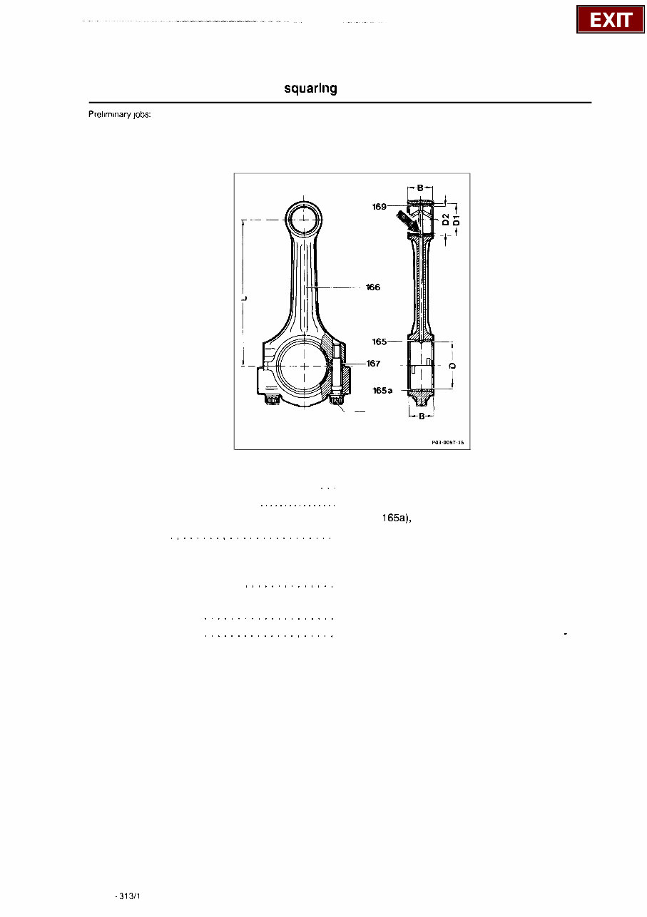
03-313 Reconditioning and squaririg connecting rods Prellmlnary jobs: Pistons removed (03-316). 168 1-B--] PO3-0097.15 Connecting rod bolts (168) and sleeves (167) . . . oil. Connecting rod bearing cap . . . . . . . . . . . . . . . . attach without connecting rod bearing shells (165, 165a), remove, 30 Nm (item 1). Basic bore (D) . . . . . . . . . . . . . . . . . . . . . . . . . measure, max. 51.619 mm, if dimension is exceeded, machine bearing cap down max. 0.02 mm (item 2). Connecting rod bushing (169) . . . . . . . . . . . . . . press in, approx. 2450 N and machine or ream out (items 3, 4). Connecting rod (166) . . . . . . . . . . . . . . . . . . . . touch up lateral thrust surfaces (item 5). Connecting rod (166) . . . . . . . . . . . . . . . . . . . . square with connecting rod tester (items 6 - 8). Caution! The connecting rod bearing bore and connecting rod bushing bore must be parallel to one another. 03.10 - 313/l
The 1982-1993 Mercedes-Benz 190 / 190D / 190E (W201) Service & Repair Manual is the ultimate resource for owners of these classic Mercedes-Benz models. Whether you are a DIY enthusiast or a professional mechanic, this manual is designed to provide comprehensive instructions for servicing and repairing your vehicle.
This manual covers the 1982-1993 Mercedes-Benz 190, 190D, and 190E models, commonly known as the W201 series. These cars were renowned for their quality engineering and timeless design. With this manual, you will have all the information you need to keep your Mercedes-Benz 190 in top condition.
Inside this service and repair manual, you will find detailed step-by-step instructions for a wide range of maintenance tasks, including:
Engine overhaul and rebuilding
Transmission and drivetrain maintenance
Brake system repairs
Suspension and steering adjustments
Electrical system troubleshooting
And much more...
By following the clear and concise instructions provided in this manual, you can save time and money by performing regular maintenance and minor repairs at home. Whether you are replacing a worn-out part or need to diagnose and fix a complex issue, this manual has got you covered.
With its easy-to-follow format and detailed diagrams, the 1982-1993 Mercedes-Benz 190 / 190D / 190E (W201) Service & Repair Manual is an essential companion for any owner or mechanic working on these classic Mercedes-Benz models.

 Service & Repair Manual")