

1997-2005 Mazda Protege Service & Repair Manual
What's Included?
Fast Download Speeds
Online & Offline Access
Access PDF Contents & Bookmarks
Full Search Facility
Print one or all pages of your manual
00
GENERAL INFORMATION
00–00–1
SECTION
00–00
Toc of SCT
GENERAL INFORMATION . . . . 00-00
Toc of SCT
00–00 GENERAL INFORMATION
HOW TO USE THIS MANUAL . . . . . . . . . 00–00–1
Range of Topics . . . . . . . . . . . . . . . . . . 00–00–1
Service Procedure. . . . . . . . . . . . . . . . . 00–00–2
Symbols . . . . . . . . . . . . . . . . . . . . . . . . 00–00–3
Advisory Messages . . . . . . . . . . . . . . . . 00–00–4
Troubleshooting Procedure . . . . . . . . . . 00–00–5
Procedures for Use . . . . . . . . . . . . . . . . 00–00–6
UNITS . . . . . . . . . . . . . . . . . . . . . . . . . . . . 00–00–11
Conversion to SI Units (Système International
d'Unités) . . . . . . . . . . . . . . . . . . . . . . . 00–00–11
Rounding Off . . . . . . . . . . . . . . . . . . . . . 00–00–11
Upper and Lower Limits . . . . . . . . . . . . 00–00–11
FUNDAMENTAL PROCEDURES . . . . . . 00–00–11
Protection of the Vehicle . . . . . . . . . . . . 00–00–11
Preparation of Tools and Measuring
Equipment . . . . . . . . . . . . . . . . . . . . . . 00–00–12
Special Service Tools . . . . . . . . . . . . . . 00–00–12
Oil Leakage Inspection . . . . . . . . . . . . . 00–00–12
Disconnection of the Negative Battery
Cable. . . . . . . . . . . . . . . . . . . . . . . . . . 00–00–13
Removal of Parts. . . . . . . . . . . . . . . . . . 00–00–13
Disassembly . . . . . . . . . . . . . . . . . . . . . 00–00–13
Inspection During Removal,
Disassembly . . . . . . . . . . . . . . . . . . . . 00–00–13
Arrangement of Parts . . . . . . . . . . . . . . 00–00–14
Cleaning of Parts. . . . . . . . . . . . . . . . . . 00–00–14
Reassembly . . . . . . . . . . . . . . . . . . . . . 00–00–14
Adjustment . . . . . . . . . . . . . . . . . . . . . . 00–00–15
Rubber Parts and Tubing . . . . . . . . . . . 00–00–15
Hose Clamps. . . . . . . . . . . . . . . . . . . . . 00–00–15
Torque Formulas . . . . . . . . . . . . . . . . . . 00–00–15
Vise . . . . . . . . . . . . . . . . . . . . . . . . . . . . 00–00–16
Dynamometer . . . . . . . . . . . . . . . . . . . . 00–00–16
INSTALLATION OF RADIO SYSTEM. . . 00–00–16
ELECTRICAL SYSTEM. . . . . . . . . . . . . . 00–00–16
Electrical Parts . . . . . . . . . . . . . . . . . . . 00–00–16
Wiring Harness . . . . . . . . . . . . . . . . . . . 00–00–17
Connectors . . . . . . . . . . . . . . . . . . . . . . 00–00–17
Terminals . . . . . . . . . . . . . . . . . . . . . . . 00–00–18
Sensors, Switches, and Relays . . . . . . 00–00–19
Wiring Harness . . . . . . . . . . . . . . . . . . . 00–00–19
Fuse . . . . . . . . . . . . . . . . . . . . . . . . . . . 00–00–19
Electrical Troubleshooting Tools . . . . . 00–00–20
Precautions Before Welding . . . . . . . . 00–00–20
JACKING POSITIONS. . . . . . . . . . . . . . . 00–00–21
Front . . . . . . . . . . . . . . . . . . . . . . . . . . . 00–00–21
Rear . . . . . . . . . . . . . . . . . . . . . . . . . . 00–00–21
VEHICLE LIFT (2 SUPPORTS) AND SAFETY
STAND (RIGID RACK) POSITION . . . . 00–00–22
Vehicle Lift Positions . . . . . . . . . . . . . . 00–00–22
Safety Stand Positions . . . . . . . . . . . . . 00–00–22
TOWING. . . . . . . . . . . . . . . . . . . . . . . . . . 00–00–22
Tiedown Hooks . . . . . . . . . . . . . . . . . . 00–00–23
IDENTIFICATION NUMBER LOCATIONS00–00–24
Vehicle Identification Number (VIN) . . . 00–00–24
Chassis Number . . . . . . . . . . . . . . . . . . 00–00–24
Engine Identification Number . . . . . . . . 00–00–24
SAE STANDARDS . . . . . . . . . . . . . . . . . 00–00–25
ABBREVIATIONS . . . . . . . . . . . . . . . . . . 00–00–26
PRE-DELIVERY INSPECTION . . . . . . . . 00–00–27
Pre-Delivery Inspection Table . . . . . . . 00–00–27
SCHEDULED MAINTENANCE . . . . . . . . 00–00–29
Scheduled Maintenance Table . . . . . . 00–00–29
End of Toc
HOW TO USE THIS MANUAL
A3U000000001W01
Range of Topics
• This manual contains procedures for performing all required service operations. The procedures are divided
into the following five basic operations:
— Removal/Installation
— Disassembly/Assembly
— Replacement
— Inspection
— Adjustment
• Simple operations which can be performed easily just by looking at the vehicle (i.e., removal/installation of
parts, jacking, vehicle lifting, cleaning of parts, and visual inspection) have been omitted.
GENERAL INFORMATION
00–00–2
Service Procedure
Inspection, adjustment
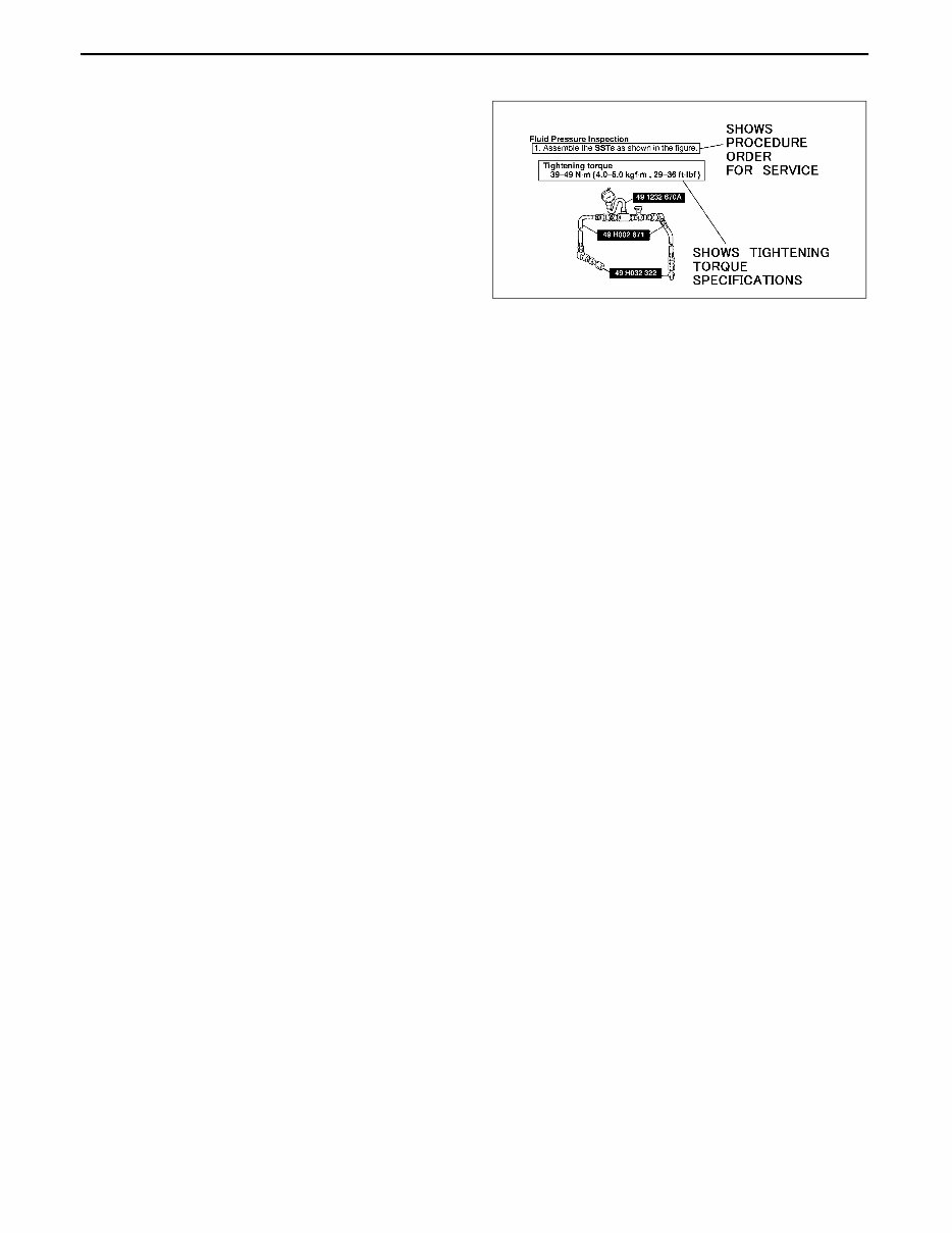
• Inspection and adjustment procedures are
divided into steps. Important points regarding the
location and contents of the procedures are
explained in detail and shown in the illustrations.
ZLU0000W208
GENERAL INFORMATION
00–00–3
00–00
Repair procedure
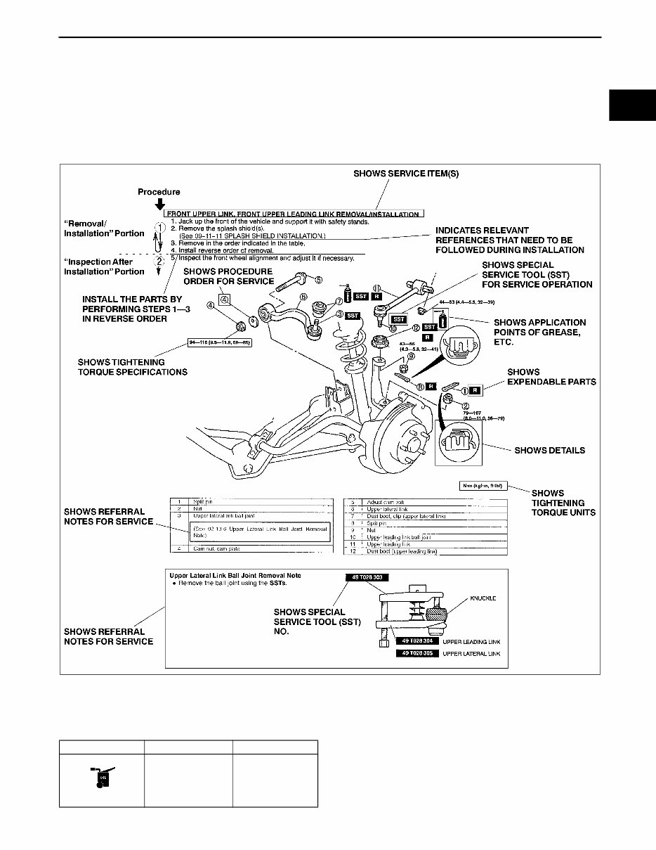
1. Most repair operations begin with an overview illustration. It identifies the components, shows how the parts fit
together, and describes visual part inspection. However, only removal/installation procedures that need to be
performed methodically have written instructions.
2. Expendable parts, tightening torques, and symbols for oil, grease, and sealant are shown in the overview
illustration. In addition, symbols indicating parts requiring the use of special service tools or equivalent are also
shown.
3. Procedure steps are numbered and the part that is the main point of that procedure is shown in the illustration
with the corresponding number. Occasionally, there are important points or additional information concerning a
procedure. Refer to this information when servicing the related part.
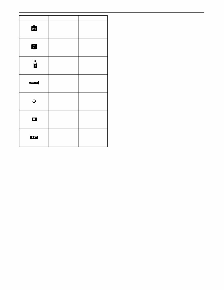
Symbols
• There are eight symbols indicating oil, grease, fluids, sealant, ane the use of SST or equivalent. use. These
symbols show application points or use of these materials during service.
YLU000WA0
Symbol Meaning Kind
Apply oil
New appropriate
engine oil or gear
oil
GENERAL INFORMATION
00–00–4
Advisory Messages
• You'll find several Warnings, Cautions, Notes, Specifications and Upper and Lower Limits in this manual.
Warning
• A Warning indicates a situation in which serious injury or death could result if the warning is ignored.
Caution
• A Caution indicates a situation in which damage to the vehicle or parts could result if the caution is ignored.
Note
• A Note provides added information that will help you to complete a particular procedure.
Specification
• The values indicate the allowable range when performing inspections or adjustments.
Upper and lower limits
• The values indicate the upper and lower limits that must not be exceeded when performing inspections or
adjustments.
Apply brake fluid
New appropriate
brake fluid
Apply automatic
transaxle/
transmission fluid
New appropriate
automatic
transaxle/
transmission fluid
Apply grease
Appropriate
grease
Apply sealant
Appropriate
sealant
Apply petroleum
jelly
Appropriate
petroleum jelly
Replace part
O-ring, gasket,
etc.
Use SST or
equivalent
Appropriate tools
Symbol Meaning Kind
GENERAL INFORMATION
00–00–5
00–00
Troubleshooting Procedure
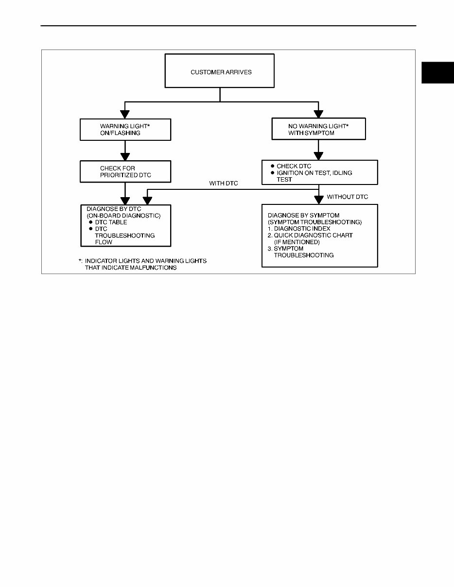
Basic flow of troubleshooting
DTC troubleshooting flow (on-board diagnostic)
• Diagnostic trouble codes (DTCs) are important hints for repairing malfunctions that are difficult to simulate.
Perform the specific DTC diagnostic inspection to quickly and accurately diagnose the malfunction.
• The on-board diagnostic function is used during inspection. When a DTC is shown specifying the cause of a
malfunction, continue the diagnostic inspection according to the items indicated by the on-board diagnostic
function.
Diagnostic index
• The diagnostic index lists the symptoms of specific malfunctions. Select the symptoms related or most closely
relating to the malfunction.
Quick diagnosis chart (If mentioned)
• The quick diagnosis chart lists diagnosis and inspection procedures to be performed specifically relating to the
cause of the malfunction.
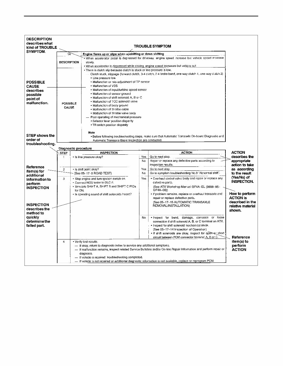
Symptom troubleshooting
• Symptom troubleshooting quickly determines the location of the malfunction according to symptom type.
WGIWXX0001E
GENERAL INFORMATION
00–00–6
Procedures for Use
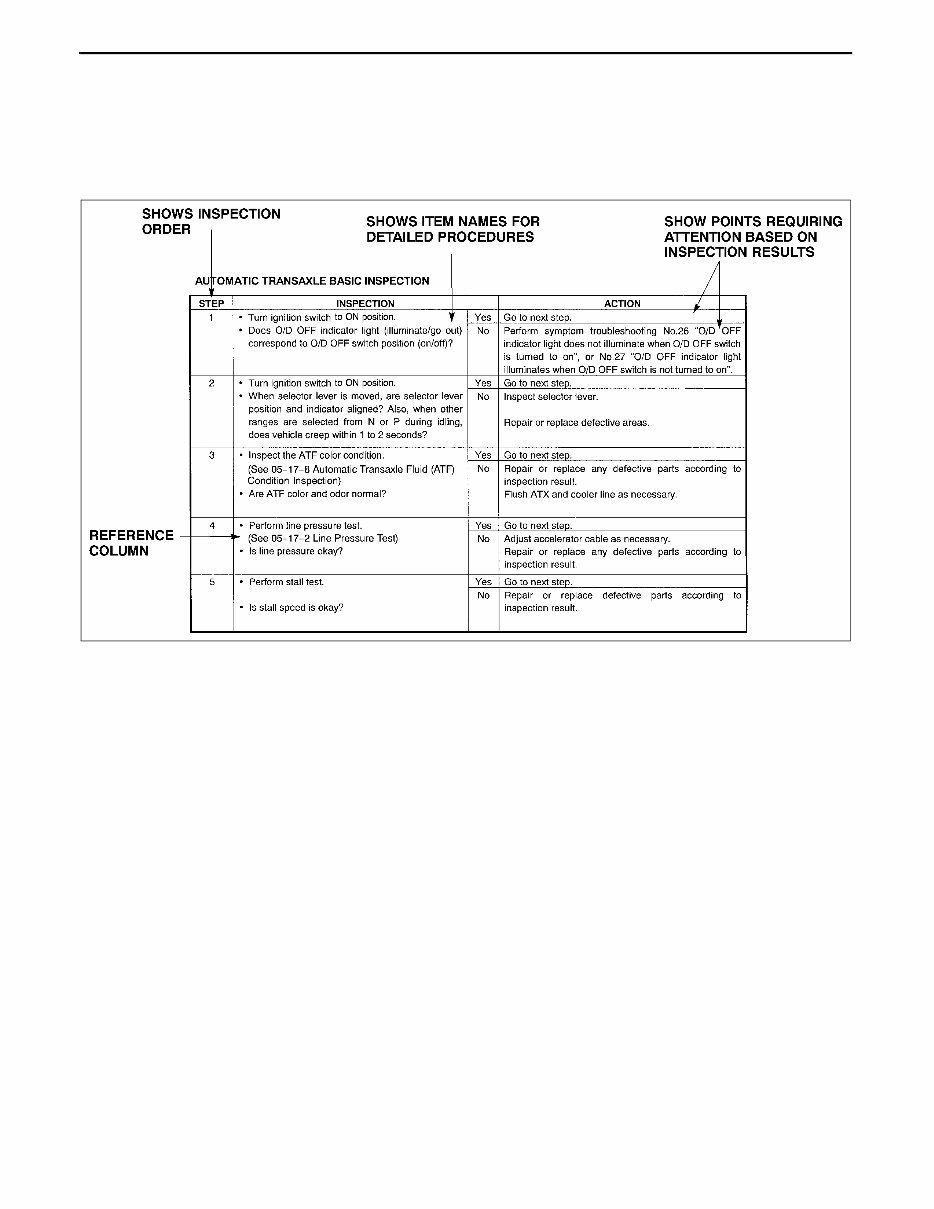
Using the basic inspection (section 05)
• Perform the basic inspection procedure before symptom troubleshooting.
• Perform each step in the order shown.
• The reference column lists the location of the detailed procedure for each basic inspection.
• Although inspections and adjustments are performed according to the reference column procedures, if the
cause of the malfunction is discovered during basic inspection, continue the procedures as indicated in the
remarks column.
YLU000WA8

GENERAL INFORMATION
00–00–7
00–00
Using the DTC troubleshooting flow
• DTC troubleshooting flow shows diagnostic procedures, inspection methods, and proper action to take for each
DTC.
YLU000WA1
GENERAL INFORMATION
00–00–8
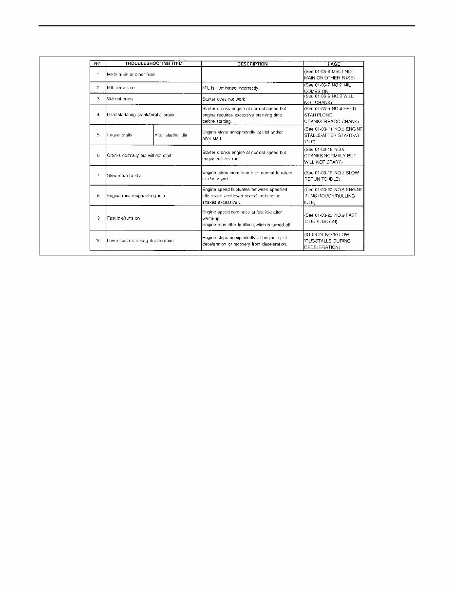
Using the diagnostic index
• The symptoms of the malfunctions are listed in the diagnostic index for symptom troubleshooting.
• The exact malfunction symptoms can be selected by following the index.
YLU000WA9
GENERAL INFORMATION
00–00–9
00–00
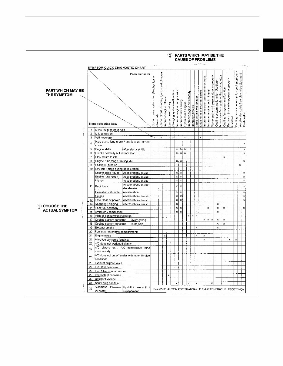
Using the quick diagnosis chart
• The chart lists the relation between the symptom and the cause of the malfunction.
• The chart is effective in quickly narrowing down the relation between symptom and cause of the malfunction. It
also specifies the area of the common cause when multiple malfunction symptoms occur.
• The appropriate diagnostic inspection relating to malfunction cause as specified by the symptoms can be
selected by looking down the diagnostic inspection column of the chart.
YLU000WAA
GENERAL INFORMATION
00–00–10
Using the symptom troubleshooting
• Symptom troubleshooting shows diagnostic procedures, inspection methods, and proper action to take for
each trouble symptom.
End Of Sie
YLU000WA2
You're Reading a Preview
What's Included?
Fast Download Speeds
Online & Offline Access
Access PDF Contents & Bookmarks
Full Search Facility
Print one or all pages of your manual
$36.99
Viewed 63 Times Today


Secure transaction
What's Included?
Fast Download Speeds
Online & Offline Access
Access PDF Contents & Bookmarks
Full Search Facility
Print one or all pages of your manual
$36.99
This comprehensive service and repair manual covers the Mazda Protege from 1997 to 2005. It provides detailed illustrations, diagrams, wiring schematics, and exact specifications along with step-by-step instructions to help you tackle repairs and maintenance with ease. Whether you are a do-it-yourself enthusiast or a seasoned mechanic, every page is designed for full printability to enhance your workshop or garage experience.
- 1997-2005 Mazda Protege Service & Repair Manual
- 1997-2005 Mazda Protege Workshop Repair Manual
- 1997-2005 Mazda Protege Factory Service Repair Manual
- 1997-2005 Mazda Protege Repair Manual
- 1997-2005 Mazda Protege Service Manual
- 1997-2005 Mazda Protege Service Manual Repair
Product Details:
- File Format: PDF
- Language: English
- Specifications: Fully Printable, Zoom IN/OUT
- Delivery: Instant Access
- Requirements: Adobe Reader & Windows
- Compatible: All Versions of Windows & Mac


