

1990-1997 Mazda MX-5 Miata NA Series Service & Repair Manual
What's Included?
Fast Download Speeds
Offline Viewing
Access Contents & Bookmarks
Full Search Facility
Print one or all pages of your manual
HEATER SYSTEM
1990-92 Heater Systems
DESCRIPTION & OPERATION
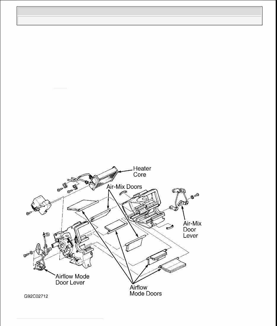
Heater case, mounted under center of instrument panel, contains airflow mode door and air-mix (temperature
blend) door. See Fig. 1 . Blower case, mounted under right end of instrument panel, contains recirculated/fresh
air door. All doors are controlled manually from control panel by cable.
Blower motor relay, in left rear corner of engine compartment (on relay cluster), supplies power to blower
motor. Blower resistors, on bottom of blower case, determine blower speed.
Fig. 1: Exploded View of Heater Case
Courtesy of MAZDA MOTORS CORP.
WARNING: To avoid injury from accidental air bag deployment, read and carefully
follow all SERVICE PRECAUTIONS and DISABLING & ACTIVATING AIR
BAG SYSTEM procedures in AIR BAG article in the
ACCESSORIES/SAFETY EQUIPMENT Section.
1991 Mazda MX-5 Miata
HEATER SYSTEM 1990-92 Heater Systems
1991 Mazda MX-5 Miata
HEATER SYSTEM 1990-92 Heater Systems

ADJUSTMENTS
AIRFLOW MODE DOOR
Set airflow mode control lever to vent position. Disconnect control cable at airflow mode door lever. Extend
airflow mode door lever until it stops, and hold it there. See Fig. 1 . Attach control cable to door lever and clip.
Ensure control lever moves freely between defrost and vent positions.
AIR-MIX (TEMPERATURE BLEND) DOOR
Set temperature control lever to maximum hot position. Disconnect control cable at air-mix door lever. See Fig.
1 . Extend air-mix door lever until it stops, and hold it there. Attach control cable to door lever and clip. Ensure
control lever moves freely between hot and cold positions.
RECIRCULATED/FRESH AIR DOOR
Set recirculated/fresh air control lever to fresh position. Disconnect control cable at recirculated/fresh air door
lever. Retract recirculated/fresh air door lever until it stops, and hold it there. Attach control cable to door lever
and clip. Ensure control lever moves freely between recirculated air and fresh air positions.
TESTING
BLOWER MOTOR CIRCUIT
1. Check 30-amp HEATER circuit breaker in passenger compartment fuse panel. If Red button has not
popped out, go to next step. If Red button has popped out, repair short circuit and press Red button to
reset circuit breaker.
2. Turn ignition on. Turn blower switch to 4th position (high). Check voltage at Blue wire terminal of 2-
wire blower motor connector on bottom of blower case. If no voltage is present, repair wiring between
circuit breaker and blower motor.
3. If battery voltage is present, turn off blower switch and A/C switch (if equipped). Check voltage at
Blue/Red wire terminal of blower resistor 1-wire connector. If no voltage is present, replace blower
motor. If battery voltage is present, check voltage at Blue/White wire terminal of blower resistor
connector.
4. If no voltage is present, replace blower resistor. If battery voltage is present, check voltage at Blue/Red
WARNING: To avoid injury from accidental air bag deployment, read and carefully
follow all SERVICE PRECAUTIONS and DISABLING & ACTIVATING AIR
BAG SYSTEM procedures in AIR BAG article in the
ACCESSORIES/SAFETY EQUIPMENT Section.
NOTE: Blower resistor uses a 1-wire connector and a 4-wire connector. The wire
in the 1-wire connector is Blue/Red, and one of the wires in the 4-wire
connector is Blue/Red. Check voltage at appropriate wire.
1991 Mazda MX-5 Miata
HEATER SYSTEM 1990-92 Heater Systems

wire terminal of blower resistor 4-wire connector. If no voltage is present, replace blower resistor.
5. If battery voltage is present, check voltage at Blue/Green wire terminal of blower resistor connector. If no
voltage is present, replace blower resistor. If battery voltage is present, check voltage at Blue/Yellow wire
terminal of blower resistor connector.
6. If no voltage is present, replace blower resistor. If battery voltage is present, turn ignition on and blower
switch to 4th position (high). Check voltage at Black wire terminal of blower switch connector. If battery
voltage is present, repair wiring between blower switch and ground.
7. If no voltage is present, turn ignition switch, blower switch and A/C switch off. Check voltage at
Blue/White wire terminal of blower switch connector. If no voltage is present, repair wiring between
blower resistor and blower switch.
8. If battery voltage is present, check voltage at Blue/Red wire terminal of blower switch connector. If no
voltage is present, repair wiring between blower resistor and blower switch. If battery voltage is present,
check voltage at Blue/Green wire terminal of blower switch connector.
9. If no voltage is present, repair wiring between blower resistor and blower switch. If battery voltage is
present, check voltage at Blue/Yellow wire terminal of blower switch connector. If battery voltage is
present, replace blower switch. If no voltage is present, repair wiring between blower resistor and blower
switch.
BLOWER MOTOR
Disconnect 2-wire connector from bottom of blower motor case. Apply battery voltage across terminals.
Replace blower motor if it does not operate.
BLOWER SWITCH
With blower switch in positions indicated, check continuity between specified terminals of blower switch
connector. See Fig. 2 . If continuity is not as specified, replace blower switch.
1991 Mazda MX-5 Miata
HEATER SYSTEM 1990-92 Heater Systems
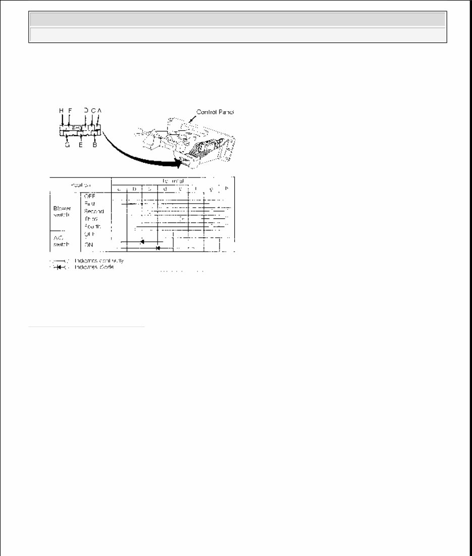
Fig. 2: Testing Blower Switch
Courtesy of MAZDA MOTORS CORP.
REMOVAL & INSTALLATION
CONTROL PANEL
Removal & Installation
Remove rear center console assembly. Remove vent outlets from center panel assembly. Remove center panel
assembly. Remove control panel screws. Pull control panel from center panel and disconnect cables. To install,
reverse removal procedure.
HEATER CORE
Removal & Installation
WARNING: To avoid injury from accidental air bag deployment, read and carefully
follow all SERVICE PRECAUTIONS and DISABLING & ACTIVATING AIR
BAG SYSTEM procedures in AIR BAG article in the
ACCESSORIES/SAFETY EQUIPMENT Section.
1991 Mazda MX-5 Miata
HEATER SYSTEM 1990-92 Heater Systems
Drain coolant. Disconnect heater hoses at engine compartment firewall. Remove grommets from holes (if
equipped). Remove instrument panel. Remove heater case. Disassemble case and remove heater core. See Fig.
1 . To install, reverse removal procedure. Fill cooling system.
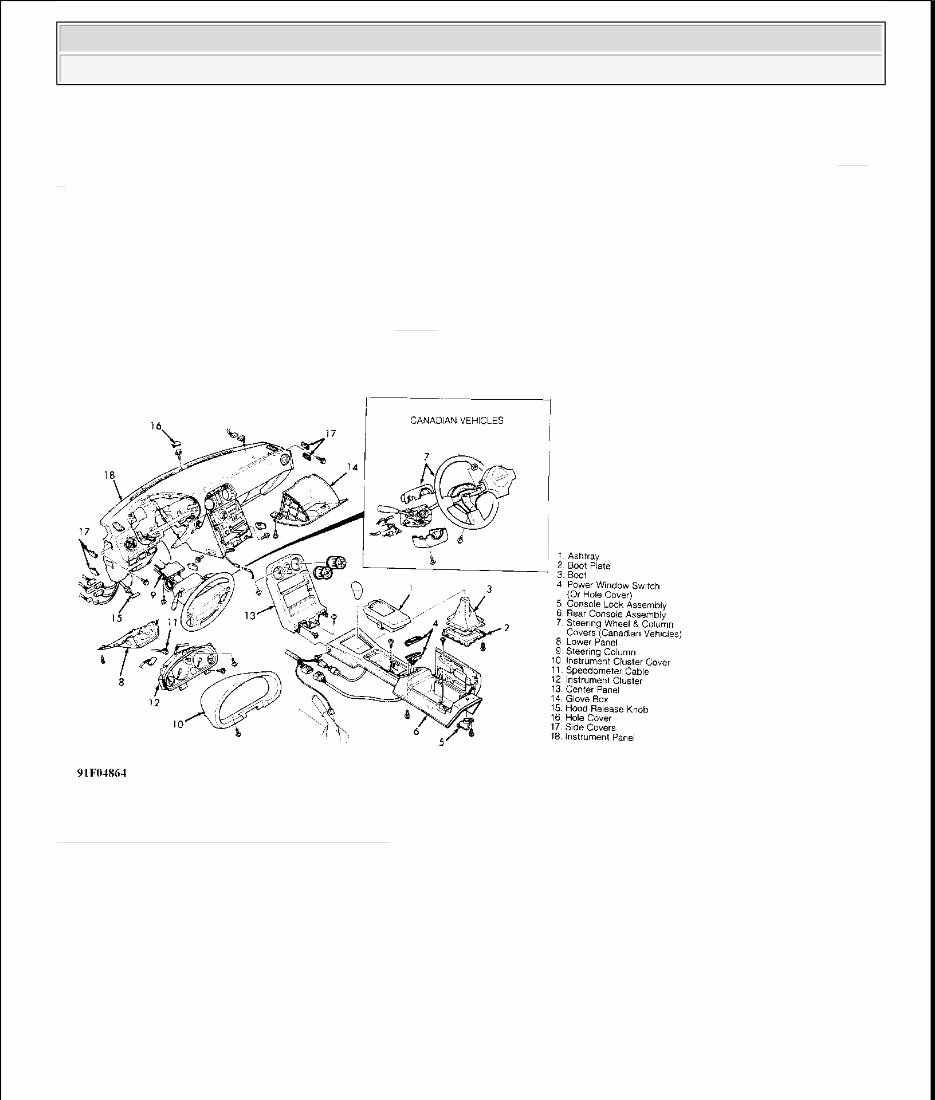
INSTRUMENT PANEL
Removal & Installation
Obtain code number and deactivate audio anti-theft system. Disconnect negative battery cable. Remove all
components in order listed in illustration. See Fig. 3 . To install, reverse removal procedure.
Fig. 3: Exploded View of Instrument Panel
Courtesy of MAZDA MOTORS CORP.
WIRING DIAGRAM
1991 Mazda MX-5 Miata
HEATER SYSTEM 1990-92 Heater Systems
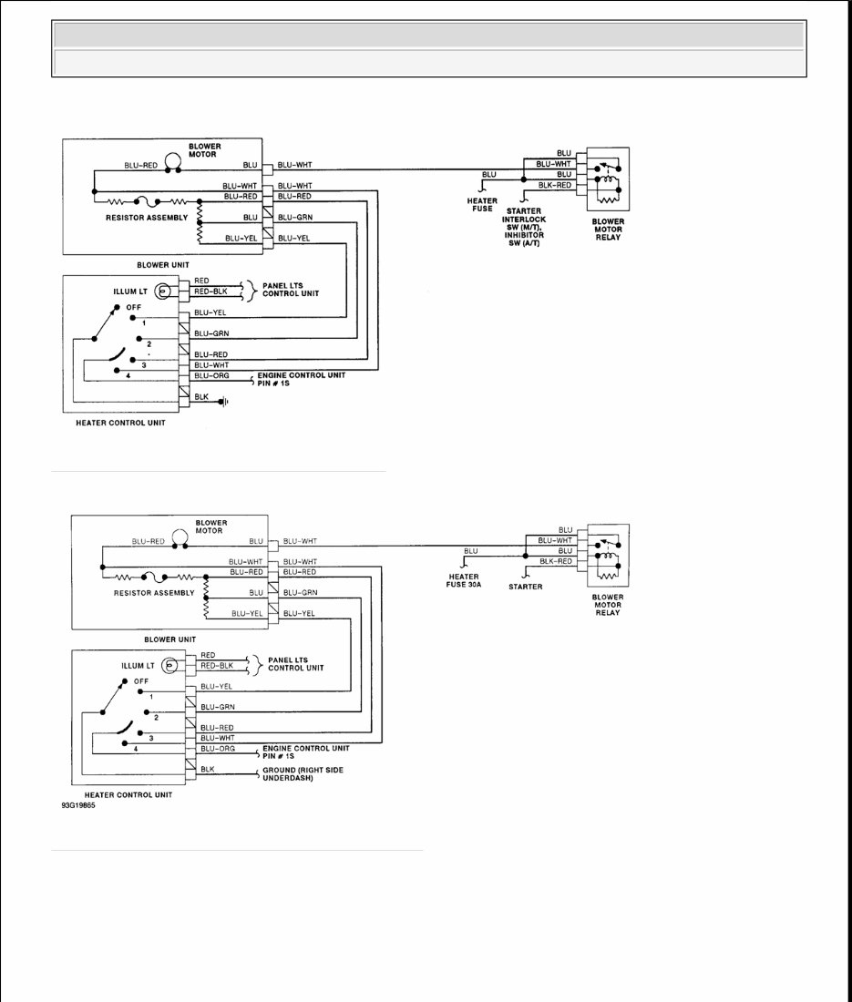
Fig. 4: Heater System Wiring Diagram (Miata)
Fig. 5: Heater System Wiring Diagram (1992 Miata)
1991 Mazda MX-5 Miata
HEATER SYSTEM 1990-92 Heater Systems
You're Reading a Preview
What's Included?
Fast Download Speeds
Offline Viewing
Access Contents & Bookmarks
Full Search Facility
Print one or all pages of your manual
$31.99
Viewed 83 Times Today


Secure transaction
What's Included?
Fast Download Speeds
Offline Viewing
Access Contents & Bookmarks
Full Search Facility
Print one or all pages of your manual
$31.99
This comprehensive 1990-1997 Mazda MX-5 (Miata) OEM Service & Repair Manual is an essential guide tailored for the NA series (1st generation) models, covering both the 1.6L and 1.8L engines. Designed with both professional mechanics and DIY enthusiasts in mind, it provides in-depth technical and service information vital for maintaining and repairing these vehicles.
Spanning over 700 pages, the manual includes detailed sections on:
- Engine operation and diagnostics
- Lubrication, cooling, and fuel/emission control systems
- Engine electrical systems
- Clutch, manual, and automatic transmission
- Suspension, propeller shaft, and axles
- Steering and braking systems
- Wheels, tires, and body electrical systems
- Heater and air conditioner systems
- Technical data, special service tools, parts index, and wiring diagrams
This manual is structured to meet the needs of Mazda technicians worldwide while reflecting the distinct specifications of the 1990-1997 Mazda MX-5 (Miata) models.


