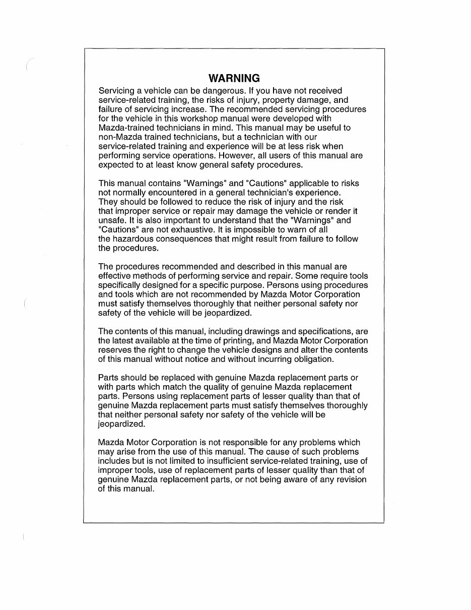
WARNING Servicing a vehicle can be dangerous. If you have not received service-related training, the risks of injury, property damage, and failure of servicing increase. The recommended servicing procedures for the vehicle in this workshop manual were developed with Mazda-trained technicians in mind. This manual may be useful to non-Mazda trained technicians, but a technician with our service-related training and experience will be at less risk when performing service operations. However, all users of this manual are expected to at least know general safety procedures. This manual contains "Warnings" and "Cautions" applicable to risks not normally encountered in a general technician's experience. They should be followed to reduce the risk of injury and the risk that improper service or repair may damage the vehicle or render it unsafe. It is also important to understand that the "Warnings" and "Cautions" are not exhaustive. It is impossible to warn of all the hazardous consequences that might result from failure to follow the procedures. The procedures recommended and described in this manual are effective methods of performing service and repair. Some require tools specifically designed for a specific purpose. Persons using procedures and tools which are not recommended by Mazda Motor Corporation must satisfy themselves thoroughly that neither personal safety nor safety of the vehicle will be jeopardized. The contents of this manual, including drawings and specifications, are the latest available at the time of printing, and Mazda Motor Corporation reserves the right to change the vehicle designs and alter the contents of this manual without notice and without incurring obligation. Parts should be replaced with genuine Mazda replacement parts or with parts which match the quality of genuine Mazda replacement parts. Persons using replacement parts of lesser quality than that of genuine Mazda replacement parts must satisfy themselves thoroughly that neither personal safety nor safety of the vehicle will be jeopardized. Mazda Motor Corporation is not responsible for any problems which may arise from the use of this manual. The cause of such problems includes but is not limited to insufficient service-related training, use of improper tools, use of replacement parts of lesser quality than that of genuine Mazda replacement parts, or not being aware of any revision of this manual.
, "
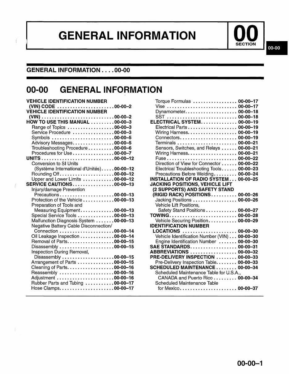
GENERAL INFORMATION GENERAL INFORMATION .... 00-00 00-00 GENERAL INFORMATION VEHICLE IDENTIFICATION NUMBER (VIN) CODE ..................... . 00-00-2 VEHICLE IDENTIFICATION NUMBER (VIN) ............................ 00-00-2 HOW TO USE THIS MANUAL . ....... . 00-00-3 Range of Topics ..• ....... • ....... 00-00-3 Service Procedure ............... . 00-00-3 Symbols ................ • ....... 00-00-5 Advisory Messages ........... • .... 00-00-5 Troubleshooting Procedure ......... . 00-00-6 Procedures for Use ............... . 00-00-7 UNITS . .......................... . 00-00-12 Conversion to SI Units (Systeme International d'Unites) .... . 00-00-12 Rounding Off. ................... . 00-00-12 Upper and Lower Limits ........... . 00-00-12 SERVICE CAUTIONS . .............. . 00-00-13 Injury/damage Prevention Precautions ............. • ...... . 00-00-13 Protection of the Vehicle ........... . 00-00-13 Preparation of Tools and Measuring Equipment ............ . 00-00-13 Special Service Tools ...... •.• .... . 00-00-13 Malfunction Diagnosis System ...... . 00-00-13 Negative Battery Cable Disconnection/ Connection ............... • .... . 00-00-14 Oil Leakage Inspection ............ • 00-00-14 Removal of Parts ............ • .... . 00-00-15 Disassembly • ................... . 00-00-15 Inspection During Removal, Disassembly ................... . 00-00-15 Arrangement of Parts ........ • .... • 00-00-15 Cleaning of Parts ................. . 00-00-16 Reassembly ..• ............ • .... • 00-00-16 Adjustment ..................... . 00-00-16 Rubber Parts and Tubing ...•.•...• . 00-00-17 Hose Clamps .................... . 00-00-17 Torque Formulas ........ • ........ 00-00-17 Vise ....... •...• .............. . 00-00-17 Dynamometer ........... •.• ...... 00-00-18 SST .......................... . 00-00-18 ELECTRICAL SySTEM .............. 00-00-19 Electrical Parts •..•...• .......... . 00-00-19 Wiring Harness ............ • ...... 00-00-19 Connectors •..• ...... • ........... 00-00-19 Terminals ..• .... • .............. . 00-00-21 Sensors, Switches, and Relays ...... 00-00-21 Wiring Harness •••• .............. . 00-00-21 Fuse ......... • ..... •...• ....... 00-00-22 Direction of View for Connector ...... 00-00-22 Electrical Troubleshooting Tools ...... 00-00-23 Precautions Before Welding ........ . 00-00-24 INSTALLATION OF RADIO SYSTEM . .. 00-00-25 JACKING POSITIONS, VEHICLE LIFT (2 SUPPORTS) AND SAFETY STAND (RIGID RACK) POSITIONS . ......... 00-00-26 Jacking Positions ................ . 00-00-26 Vehicle Lift Positions, Safety Stand Positions ........... . 00-00-27 TOWING . ......................... 00-00-28 Vehicle Securing Position .......... . 00-00-29 IDENTIFICATION NUMBER LOCATIONS ..................... 00-00-30 Vehicle Identification Number (VIN) .. . 00-00-30 Engine Identification Number ....... 00-00-30 SAE STANDARDS . ................ . 00-00-31 ABBREVIATIONS ................. . 00-00-32 PRE-DELIVERY INSPECTION ....... . 00-00-33 Pre-Delivery Inspection Table ....... . 00-00-33 SCHEDULED MAINTENANCE . ...... . 00-00-34 Scheduled Maintenance Table for U.S.A., CANADA and Puerto Rico ......... 00-00-34 Scheduled Maintenance Table for Mexico ...................... 00-00-37 00-00-1
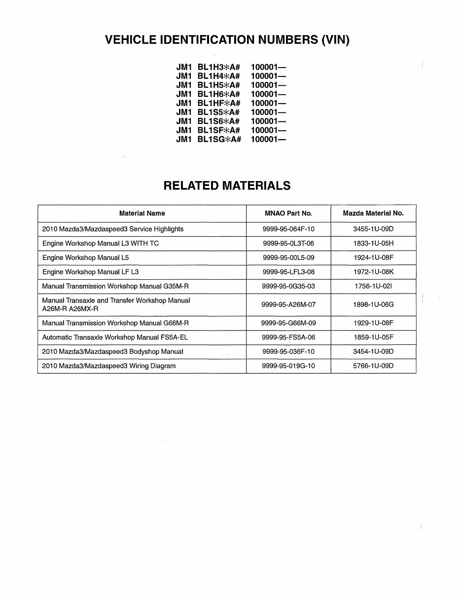
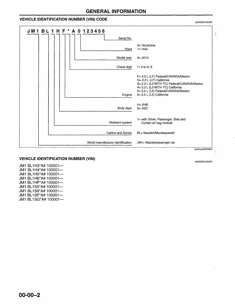
GENERAL INFORMATION VEHICLE IDENTIFICATION NUMBER (VIN) CODE JM1 BL1 H F*A0123456 I Serial No. 0= Hiroshima L...-_________ P:..,:I.:::::an..:.=,t 1= Hofu Model year A= 2010 ~---------~~ Check digit *= 0 to 9, X L...-____________ ~ F= 2.0 L (LF) Federal/CANADA/Mexico G= 2.0 L (LF) California id000000100200 3= 2.3 L (L3 WITH TC) Federal/CANADA/Mexico 4= 2.3 L (L3 WITH TC) California S= 2.S L (LS) Federal/CANADA/Mexico Engine 6= 2.S L (LS) California ~------------------------ H=SHB Body style S= 4SD 1= with Driver, Passenger, Side and Restraint system Curtain air bag module ~---------------------------- L...-_________________ C_a_r_lin_e_a_nd_S_e_ri_es BL= Mazda3/Mazdaspeed3 World manufacturer identification JM1 = Mazda/passenger car VEHICLE IDENTIFICATION NUMBER (VIN) JM1 BL1H3*A# 100001- JM1 BL1H4*A# 100001- JM1 BL1H5*A# 100001- JM1 BL1H6*A# 100001- JM1 BL1HF*A# 100001- JM1 BL1S5*A# 100001- JM1 BL1S6*A# 100001- JM1 BL1SF*A# 100001- JM1 BL1SG*A# 100001- 00-00-2 am3uuw0000624 id000000100300
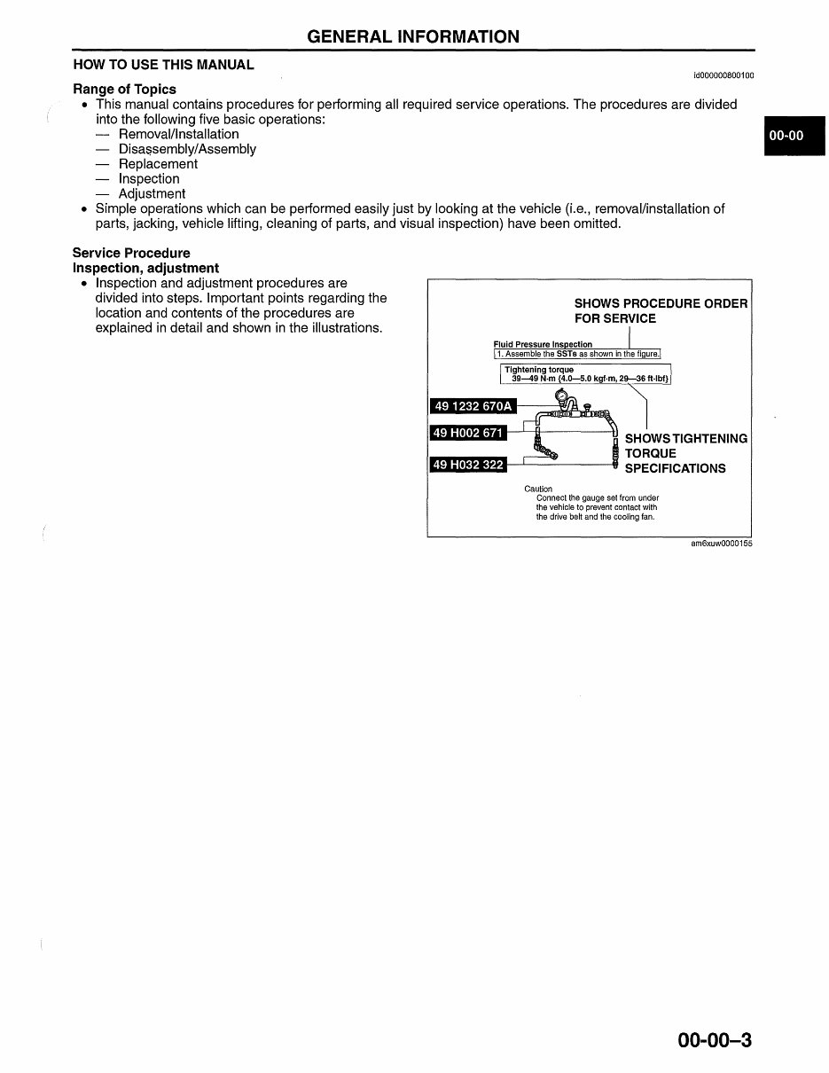
GENERAL INFORMATION HOW TO USE THIS MANUAL id000000800100 Range of Topics • This manual contains procedures for performing all required service operations. The procedures are divided into the following five basic operations: Removal/I nstallation Disas.sembly/Assembly Replacement Inspection Adjustment • Simple operations which can be performed easily just by looking at the vehicle (i.e., removal/installation of parts, jacking, vehicle lifting, cleaning of parts, and visual inspection) have been omitted. Service Procedure Inspection, adjustment • Inspection and adjustment procedures are divided into steps. Important points regarding the location and contents of the procedures are explained in detail and shown in the illustrations. SHOWS PROCEDURE ORDER FOR SERVICE SHOWS TIGHTENING TORQUE ,.., .... --'-------it SPECIFICATIONS Caution Connect the gauge set from under the vehicle to prevent contact with the drive belt and the cooling fan. am6xuw0000155 00-00-3 •
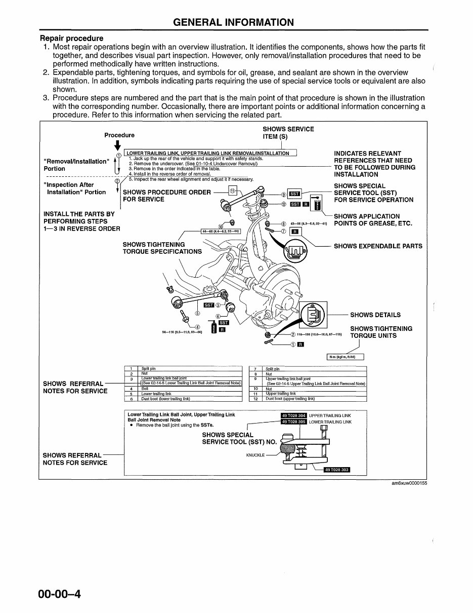
GENERAL INFORMATION Repair procedure 1. Most repair operations begin with an overview illustration. It identifies the components, shows how the parts fit together, and describes visual part inspection. However, only removal/installation procedures that need to be performed methodically have written instructions. 2. Expendable parts, tightening torques, and symbols for oil, grease, and sealant are shown in the overview illustration. In addition, symbols indicating parts requiring the use of special service tools or equivalent are also shown. 3. Procedure steps are numbered and the part that is the main point of that procedure is shown in the illustration with the corresponding number. Occasionally, there are important points or additional information concerning a procedure. Refer to this information when servicing the related part. Procedure SHOWS SERVICE ITEM (S) *~------------~ "Removal/Installation" 1. Jack up the rear of the vehicle an~ s~pport it with safety stands. RE FERENCES THAT NEED a LOWER TRAILING LINK UPPER TRAILING LINK REMOVAUINSTALLATION INDICATES RELEVANT • 2. Remove ~he undercoyer: (See?1 104 Undercover Removal) TO BE FOLLOWED DURING Portion 3. Remove In the order indicated In the table. 4. Install in the reverse order of removal. INSTALLATION "~~~~~-~t~~~ -~;;~r- ------ r~-5. Inspect the rear wheel alignment and adjust it jf necessary. SHOWS SPECIAL Installation" Portion SHOWS PROCEDURE ORDER ~~ SERVICE TOOL (SST) FOR SERVICE ~~~ _mlil FOR SERVICE OPERATION INSTALL THE PARTS BY \ ~ SHOWS APPLICATION PERFORMING STEPS ~ 43-56 {4.3-5.8,32-41) POINTS OF GREASE, ETC. 1-3 IN REVERSE ORDER ~ ~ ~~~;;rJ;:~6~~I~;;;IONS ~ SHOWS EXPENDABLE PARTS SHOWS REFERRAL NOTES FOR SERVIC E SHOWS REFERRAL -- NOTES FOR SERVICE 00-00-4 1 Split pin 2 Nut 3 ower trallng inK oall oint 7 B 9 Split pin Nut Upper trailing link ball joint SHOWS DETAILS SHOWS TIGHTENING TORQUE UNITS (See 02-1 Joint Removal Note) I (See 02-14-5 Upper Trailing Link Ball Joint Removal Note) 4 Bolt 5 Lower trailing link 6 Dust boot (lower trailing link) LowerTrailing Link Ball Joint, Upper Trailing Link Ball Joint Removal Note • Remove the ball joint using the SSTs. 10 Nut 11 Upper trailing link 12 Dust boot (upper trailing link) SHOWS SPECIAL SERVICE TOOL (SST) NO. KNUCKLE am6xuw0000155
GENERAL INFORMATION Symbols • There are eight symbols indicating oil, grease, fluids, sealant, and the use of SST or equivalent. These symbols show application points or use of these materials during service. Symbol Meaning Kind -~ New appropriate I Apply oil engine oil or gear oil • Apply brake fluid New appropriate brake fluid • Apply automatic New appropriate automatic transaxlel transaxlel transmission fluid transmission fluid ~A Appropriate I Apply grease grease ·_1 Apply sealant Appropriate sealant G Apply petroleum Appropriate jelly petroleum jelly iii Replace part O-ring, gasket, etc. ED Use SST or Appropriate tools equivalent Advisory Messages • You will find several Warnings, Cautions, Notes, Specifications and Upper and Lower Limits in this manual. Warning • A Warning indicates a situation in which serious injury or death could result if the warning is ignored. Caution • A Caution indicates a situation in which damage to the vehicle or parts could result if the caution is ignored. Note • A Note provides added information that will help you to complete a particular procedure. Specification • The values indicate the allowable range when performing inspections or adjustments. Upper and lower limits • The values indicate the upper and lower limits that must not be exceeded when performing inspections or adjustments. 00-00-5 •
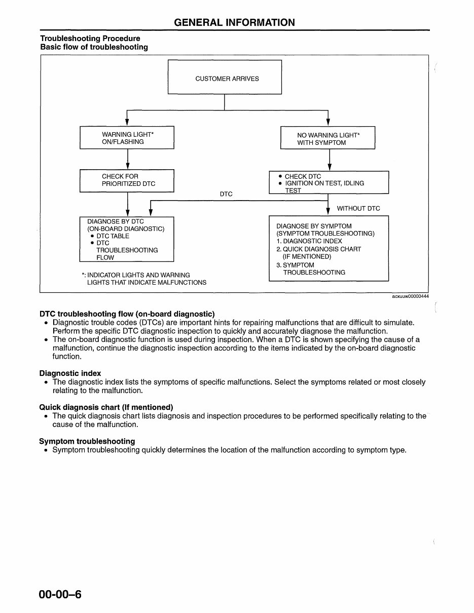
GENERAL INFORMATION Troubleshooting Procedure Basic flow of troubleshooting CUSTOMER ARRIVES WARNING LlGHT* ON/FLASHING CHECK FOR PRIORITIZED DTC DIAGNOSE BY DTC (ON-BOARD DIAGNOSTIC) • DTCTABLE • DTC TROUBLESHOOTING FLOW *: INDICATOR LIGHTS AND WARNING LIGHTS THAT INDICATE MALFUNCTIONS DTC troubleshooting flow (on-board diagnostic) I DTC NO WARNING LlGHT* WITH SYMPTOM • CHECK DTC • IGNITION ON TEST, IDLING TEST r WITHOUT DTC DIAGNOSE BY SYMPTOM (SYMPTOM TROUBLESHOOTING) 1. DIAGNOSTIC INDEX 2. QUICK DIAGNOSIS CHART (IF MENTIONED) 3. SYMPTOM TROUBLESHOOTING acxuuw00000444 • Diagnostic trouble codes (DTCs) are important hints for repairing malfunctions that are difficult to simulate. Perform the specific DTC diagnostic inspection to quickly and accurately diagnose the malfunction. • The on-board diagnostic function is used during inspection. When a DTC is shown specifying the cause of a malfunction, continue the diagnostic inspection according to the items indicated by the on-board diagnostic function. Diagnostic index • The diagnostic index lists the symptoms of specific malfunctions. Select the symptoms related or most closely relating to the malfunction. Quick diagnosis chart (If mentioned) • The quick diagnosis chart lists diagnosis and inspection procedures to be performed specifically relating to the· cause of the malfunction. Symptom troubleshooting • Symptom troubleshooting quickly determines the location of the malfunction according to symptom type. 00-00-6
Upon purchasing this manual, you will receive a .PDF file containing an email contact. After contacting us, you will receive a reply with a link to access the manual for your Mazda Speed 3 2009-2012.
This comprehensive manual covers every aspect of your vehicle, providing detailed instructions for a wide range of repairs and maintenance tasks. Whether it's an oil change or a transmission swap, the manual includes numerous illustrations and easy-to-follow text to assist you. The search function allows for easy navigation, and you can print specific pages as needed.
Designed as a Factory Service Repair Manual, it offers step-by-step guidance for maintaining and repairing your vehicle, equipping you with the knowledge typically possessed by factory-trained technicians. Owners can confidently make informed decisions about their vehicle's upkeep and repairs by utilizing the insights provided in this manual.
Our commitment extends beyond delivering a high-quality service manual; we also provide exceptional customer service, ensuring your satisfaction with your purchase.