3.0L V6
Article Text
1993 Mazda 929
For Techdoc Ltd.
Copyright © 1997 Mitchell International
Wednesday, March 24, 1999 10:52PM
ARTICLE BEGINNING
1992-93 MAZDA ENGINES
3.0L V6
929
* PLEASE READ THIS FIRST *
NOTE: For engine repair procedures not covered in this article,
see ENGINE OVERHAUL PROCEDURES - GENERAL INFORMATION article
in the GENERAL INFORMATION section.
ENGINE IDENTIFICATION
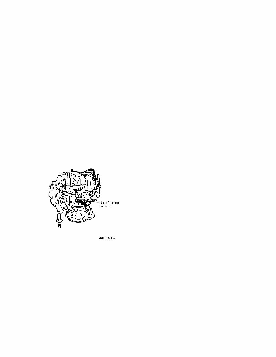
Engine code and number are stamped on rear of cylinder block,
above flywheel. See Fig. 1. Engine identification code information is
not available from manufacturer.
Fig. 1: Identifying Engine Code & Number Location
Courtesy of Mazda Motors Corp.
ADJUSTMENTS
VALVE CLEARANCE ADJUSTMENT
1) No valve clearance adjustment is required, as Hydraulic
Lash Adjusters (HLA) are used. If noise exists when engine is started,
operate engine at 2000-3000 RPM for 10 minutes.
2) If noise stops, valve lash adjuster is operating
correctly. If noise still exists, check engine oil level and oil
pressure. Oil pressure should be within specification. See ENGINE
LUBRICATION SYSTEM under ENGINE OILING. If oil pressure is not within
specification, check for defective engine components.
3) If oil pressure is okay, remove valve cover. Push downward
on valve lash adjuster. If valve lash adjuster pushes downward,
3.0L V6
Article Text (p. 2)
1993 Mazda 929
For Techdoc Ltd.
Copyright © 1997 Mitchell International
Wednesday, March 24, 1999 10:52PM
replace valve lash adjuster. See VALVE LASH ADJUSTER under REMOVAL &
INSTALLATION. If valve lash adjuster does not push downward, check for
worn or damaged camshaft and components.
NOTE: DO NOT remove HLA unless necessary, as "O" ring may be
damaged during removal. Before installing valve cover, apply
sealant on cylinder head at designated areas. See Fig. 10.
REMOVAL & INSTALLATION
NOTE: For installation reference, label all electrical connectors,
vacuum hoses and fuel lines before removal. Also place
mating marks on engine hood and other major assemblies
before removal.
CAUTION: When battery is disconnected, radio will go into anti-theft
protection mode. Obtain radio anti-theft protection code
from owner and deactivate radio anti-theft function prior
to disconnecting battery.
FUEL PRESSURE RELEASE
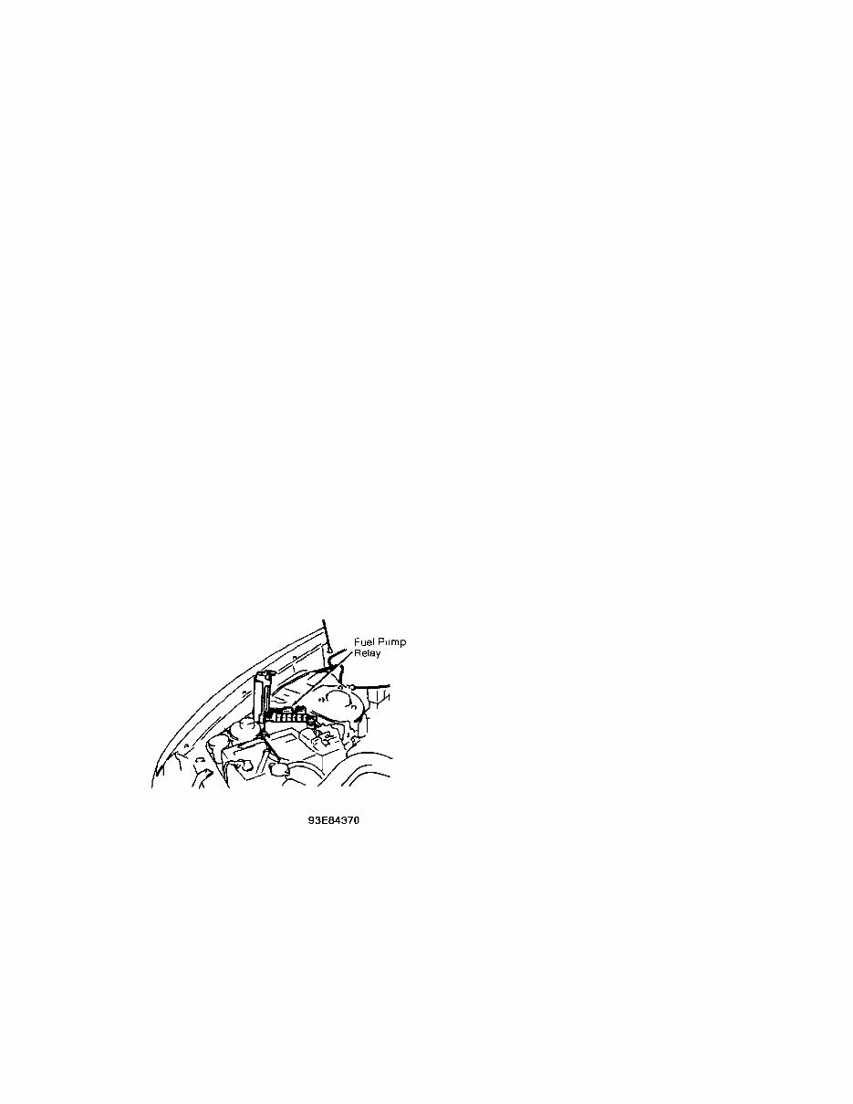
Start engine and disconnect fuel pump relay, located on right
side of engine compartment, near battery. See Fig. 2. After engine
dies, turn ignition off and reconnect fuel pump relay.
Fig. 2: Locating Fuel Pump Relay
Courtesy of Mazda Motors Corp.
ENGINE
Removal
1) Release fuel pressure. See FUEL PRESSURE RELEASE under
REMOVAL & INSTALLATION. Disconnect battery cables and remove battery
and battery tray. Remove hood. Raise and support vehicle. Remove
undercover. Drain engine oil. Disconnect exhaust pipes from exhaust
manifolds.
2) Disconnect and plug automatic transmission cooling lines
from radiator. Lower vehicle and drain engine coolant. Remove fresh
3.0L V6
Article Text (p. 3)
1993 Mazda 929
For Techdoc Ltd.
Copyright © 1997 Mitchell International
Wednesday, March 24, 1999 10:52PM
air duct, air cleaner and air intake tube. Disconnect accelerator
cable.
3) Remove cooling fan and fan shroud. Remove radiator hoses
and all drive belts. Remove spark plug cables and spark plugs. Remove
canister and power brake vacuum hoses. Cover fuel hose fitting with
rag to prevent fuel spray during removal. Remove fuel hoses as
necessary. Plug disconnected hoses to prevent fuel leakage. Remove
appropriate wiring and hoses and remove upper intake manifold.
4) Disconnect heater hoses from engine. Disconnect engine
wiring harness. Remove radiator wiring harness and radiator. Remove
alternator and adjusting bracket. Remove A/C compressor and power
steering pump, and tie them aside with hoses still connected. Support
transmission and remove engine-to-transmission bolts. Remove engine
mount nuts and remove engine.
Installation
To install, reverse removal procedure. Adjust tension of all
drive belts. Restore all fluids to proper level. Prime fuel system by
connecting jumper wire between data link connector terminals F/P and
GND in engine compartment. See Fig. 3. Turn ignition switch to ON
position for 10 seconds. Check for fuel leaks. Turn ignition switch to
OFF position. Remove jumper wire.
Fig. 3: Identifying Data Link Connector Terminals
Courtesy of Mazda Motors Corp.
INTAKE MANIFOLD
Removal
1) Apply parking brake, and block rear wheels. Release fuel
pressure. See FUEL PRESSURE RELEASE. Disconnect negative battery
cable. Remove fresh air duct, air cleaner and air intake tube.
Disconnect accelerator cable. Remove canister and power brake vacuum
hoses.
2) Cover fuel hose fitting with rag to prevent fuel spray
during removal. Remove fuel hoses as necessary. Plug disconnected
hoses to prevent fuel leakage.
3) Remove automatic transmission vacuum hose. Disconnect
engine wiring harness connectors and grounds. Remove distributor.
3.0L V6
Article Text (p. 4)
1993 Mazda 929
For Techdoc Ltd.
Copyright © 1997 Mitchell International
Wednesday, March 24, 1999 10:52PM
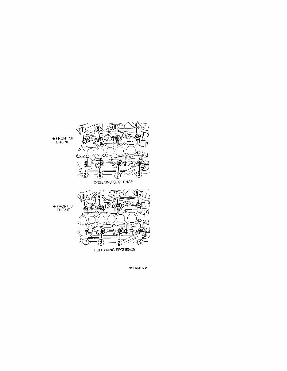
Remove upper intake manifold bolts and upper intake manifold. Loosen
intake manifold bolts in 2 steps and in sequence. See Fig. 4. Remove
intake manifold.
Installation
Using NEW gaskets and "O" rings, install intake manifold.
Tighten bolts in 2 steps to specification and in proper sequence. See
Fig. 4. See TORQUE SPECIFICATIONS TABLE at the end of this article.
Ensure all electrical and vacuum lines are properly connected. To
complete installation, reverse removal procedure.
Fig. 4: Intake Manifold Loosening & Tightening Sequence
Courtesy of Mazda Motors Corp.
EXHAUST MANIFOLDS
Removal & Installation
Remove exhaust manifold nuts at exhaust pipe. Remove exhaust
manifold heat shields and exhaust manifolds. To install, reverse
removal procedure. Install NEW gaskets. Tighten fasteners to
specification. See TORQUE SPECIFICATIONS TABLE at the end of this
article.
CYLINDER HEAD
3.0L V6
Article Text (p. 5)
1993 Mazda 929
For Techdoc Ltd.
Copyright © 1997 Mitchell International
Wednesday, March 24, 1999 10:52PM
Removal
1) Apply parking brake, and block rear wheels. Release fuel
pressure. See FUEL PRESSURE RELEASE. Disconnect negative battery
cable. Drain engine coolant. Remove air intake hose. Disconnect
accelerator cable from throttle body. Remove spark plug cables and
spark plugs.
2) Remove cooling fan and fan shroud. Remove all drive belts.
Remove A/C idler pulley. Remove crankshaft pulley and sensor rotor. DO
NOT damage sensor rotor. Remove coolant by-pass and upper radiator
hose.
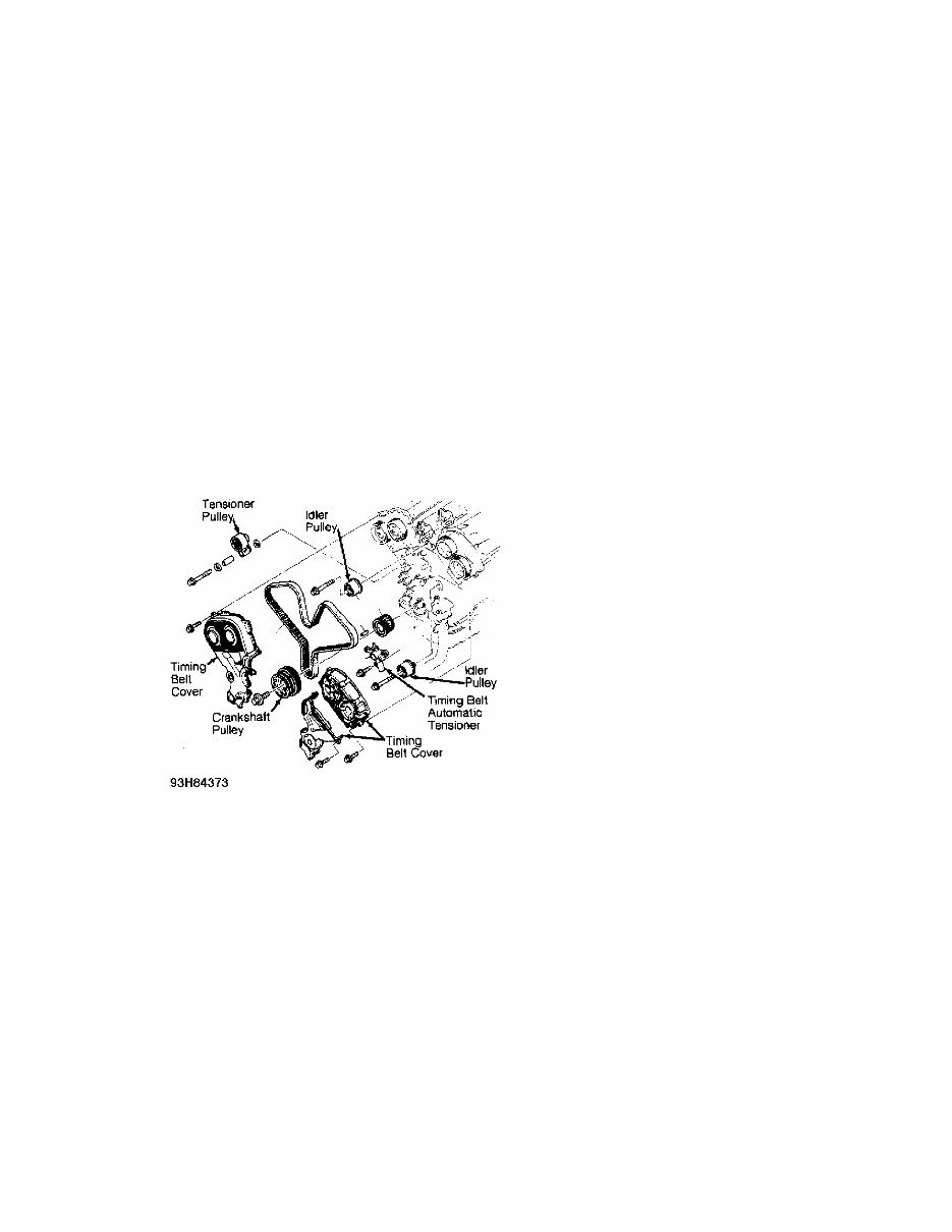
3) Remove timing belt cover and gasket. See Fig. 5. Turn
crankshaft to align match marks of pulleys. See Fig. 6. Remove timing
belt upper idler pulley. Remove timing belt and timing belt automatic
tensioner. Mark timing belt rotation direction if belt is to be
reused.
Fig. 5: Exploded View Of Timing Belt Components
Courtesy of Mazda Motors Corp.
You're Reading a Preview
What's Included?
Lifetime Access
Access Contents & Bookmarks
Print one or all pages of your manual



 Lifetime Access




