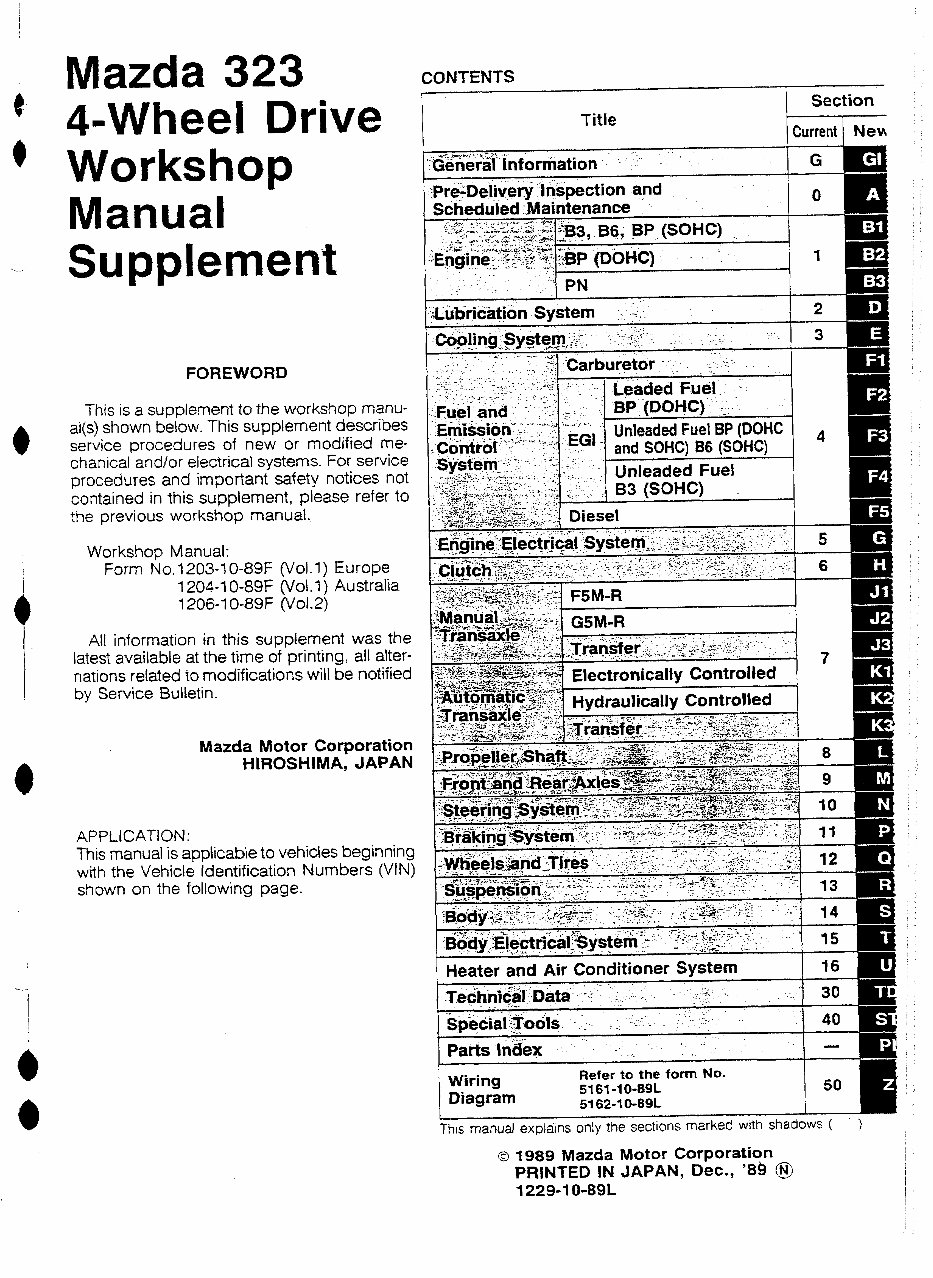
Mazda 323 4-Wheel Drive Workshop Manual CONTENTS Title Section Current ) NeH Supplement FOREWORD This is a supplement to the workshop manu- al(s) shown below. This supplement describes service procedures of new or modified me- chanical and/or electrical systems. For service procedures and important safety notices not contained in this supplement, please refer to the previous workshop manual. Workshop Manual: Form No. 1203-I O-89F (Vol. I> Europe 1204-I O-89F (vol. I > Australia I ZM-1 o-89F (vol.2) Ali information in this supplement was the latest available at the time of printing, all alter- nations related to modifications wili be notified by Service Bulletin. Mazda Motor Corporation HIROSHlMA, JAPAN APPLlCATlON: This manual is applicable to vehicles beginning with the Vehicle Identification Numbers (UN) shown on the following page. Electronically Controlled Wiring Diagram Refer to the form No. 5161-l O-89L 5162-t O-89L Thrs manual explarns only the sectIons marked with shadows ( ) 0 1989 Mazda Motor Corporation PRlNTED IN JAPAN, Dec., ‘88 @$ 1229-l O-891
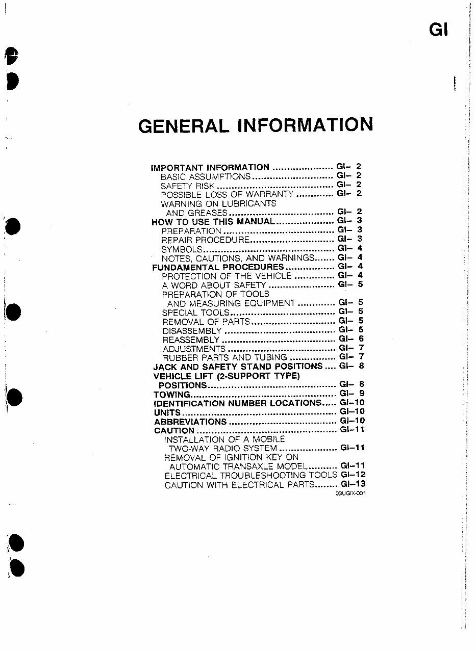
GENERAL INFORMATION IMPORTANT INFORMATION ..................... GI- 2 BASIC ASSUMPTtONS ............................ a- 2 SAFETY RlSK ........................................ GI- 2 POSSBLE LOSS OF WARRANTY ............. GI- 2 WARNiNF ON LUBRICANTS AND GREASES .................................... GI- 2 HOW TO USE THIS MANUAL.. .................. Gl- 3 PREPARATION ...................................... Gl- 3 REPAIR PROCEDURE ............................. Gl- 3 SYMBOLS ............................................. a- 4 NOTES, CAUTIONS, AND WARNINGS ....... Gl- 4 FUNDAMENTAL PROCEDURES ................. Gl- 4 PROTECTION OF THE VEHICLE .............. Gi- 4 A WORD ABOUT SAFETY ....................... Gl- 5 PREPARATION OF TOOLS AND MEASURING EQUIPMENT ............. GI- 5 SPECIAL TOOLS .................................... Gt- 5 REMOVAL OF PARTS ............................. GI- 5 DISASSEMBLY ...................................... Gi- 5 REASSEMBLY ....................................... Gl- 6 ADJUSTMENTS ..................................... GC- 7 RUBBER PARTS AND TUBING ................ Gl- 7 JACK AN5 SAFETY STAN5 POSITDNS .... Gl- 8 VEHICLE LIFT (Z-SUPPORT TYPE) POSITIONS ............................................ GI- 8 TOWING .................................................. GL 9 IDENTIFICATION NUMBER LOCATIONS ..... GI-10 UNITS ..................................................... GI-I 0 ABBREVIATIONS ..................................... Gl-I 0 CAUTION ................................................ Gl-I 1 1NSTALLATtON OF A MOBlLE TWO-WAY RADIO SYSTEM .................... GI-II REMOVAL OF tGNIT1ON KEY ON AUTOMATIC TRANSAXLE MODEL .......... Gl-11 ELECTRICAL TROUBLESHOOTlNG TOOLS GI-12 CAUTION WITH ELECTRICAL PARTS ........ Gl-13 03UGIX-001
GI IMPORTANT tNFORMATlUN IMPORTANT INFORMATION 1 .ftl 1 BASIC ASSUMPTIONS This workshop manual assumes that you have certain special tools that are necessary for the safe and effi- cient performance of service operations on Mazda vehicles and that you know how to use them properly. It also assumes that you are familiar with automobile systems and basic service and repair procedures. You should not attempt to use this manual unless these assumptions are correct and you understand the conse- quences described below. SAFETY RlSK This manual contains certain notes, warnings, and other precautionary information that you should carefully read and follow to reduce the risk of personal injury to yourself or others and the risk of improper service that may damage the vehicle or render it unsafe. If there is no such information in regard to any specific service method, this does not mean there is no possibility that personal safety or vehicle safety will be jeopardized by the use of incorrect methods or toots. POSSIBLE LOSS OF WARRANTY The manufacturer’s warranty on Mazda vehicles and engines can be voided if improper service or repairs are performed by persons other than those at an Authorized Mazda Dealer. WARNING ON LUBRICANTS AND GREASES ’ Avoid all prolonged and repeated contact with mineral oils, especially used oils. Used 08s contaminated during service (e.g., engine sump oils) are more irritating and more likely to cause serious effects, including skin cancer, in the event of gross and prolonged skin contact. Wash skin thoroughly after work involving oil. Protective hand cleaners may be of value provided they can be removed from the skin with water. Do not use gasoline, paraffin, or other solvents to remove oil from the skin. Lubricants and greases may be slightly irritating to the eyes. Repeated or prolonged skin contact should be avoided by wearing protective clothing if necessary. Particu- lar care should be taken with used oils and greases containing lead. Do not allow work clothing to be con- taminated with oil. Dry clean or launder such clothing at regular intervafs. 9MUGiX-502
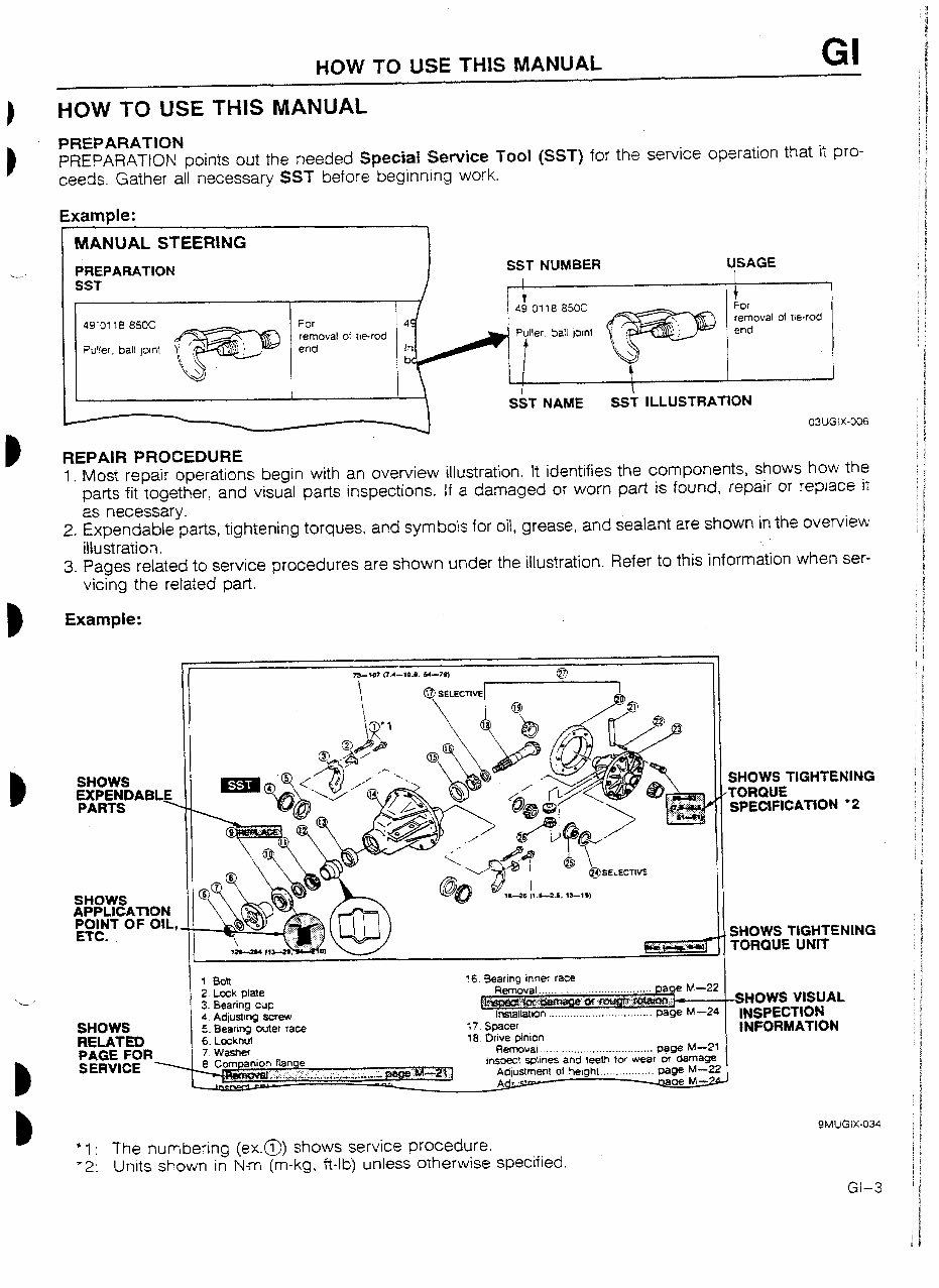
HOW TO USE TtiIS MANUAL GI HOW TO USE THIS MANUAL PREPARATION PREPARATON points out the needed SpeciaI Service Tool (SST) for the service operation that it pro- ceeds. Gather all necessary SST before beginning work. Example: MANUAL STEERING PREPARATION remova! of W-rod REPAIR PROCEDURE I. Most repair operations begin with an overview illustration. It identifies the components, shows how the parts fit together, and visual parts inspections. If a damaged or worn part is found, repair or replace it as necessary. 2. Expendable parts, tightening torques, and symbols for oil, grease, and sealant are shown in the overview iItustration. 3. Pages related to service procedures are shown under the illustration. Refer to this information when ser- vicing the related part. Example: --__ __- EXPENDABLE iI - SHOWS TlGHTENlNG TORQUE UNIT - SHOWS Zh REiAT& PAGE FOR 1 8oit 16 Bearing lnne 2. Lock plate Removal . . ,. 3. Bearrng cup I!.~ f% fnstallatbon ._ . .. ._. ... . . I A Adirtstma drew - _‘.v,--..s ----. 5. Bearing outer race :7 Spacer G I h-tnllt 1R hriu* mninn I V. LVYR*IY. .” I.~.1 7Washer Rerr&l'~ .._. . .. . ..__ . . . .. . . ..__......... page M---21 - -0mpanlon f&we inspect spllnes and teeth for wear or damage Adlustment of heloht ._._..... . . . . . DaPe k&Z? I r..r...~r.--~.~r....e.-..c~~...~.,~.-* Q SERVICE x 9MUGlx-034 ‘I : The numbering (ex.@)) shows service procedure. ‘2: Units shown in N-m (m-kg, Wb) unless otherwise specified.
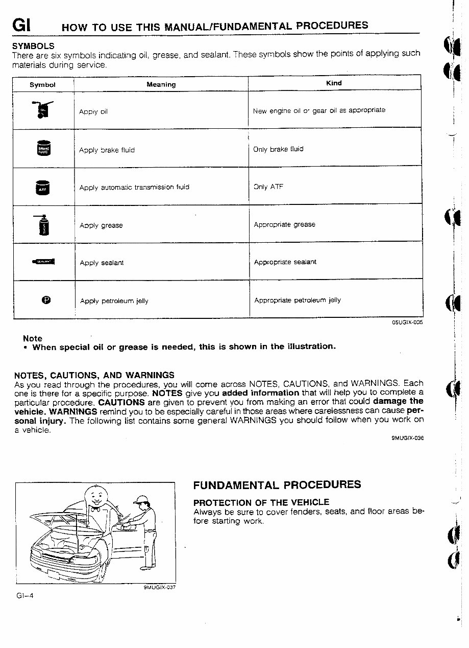
GI HOW TO USE -MS lVlANUAL/FUNDAMENTAL PROCEDURES SYMBOLS There are six symbols indicating oil, grease, and sealant. These symbols show the points of applying such materials during service. Symbol It Meaning Kind I Apply oil New engine oil or gear oil as appropriate Apply brake fluid Only brake fluid Apply automatic transmission fluid Apply grease Only ATF Appropriate grease Appty sealant Appropriate sealant m 0 Apply petroleum jelty Appropriate petroleum jelly Note l When special oil or grease is needed, this is shown in the illustration. NOTES, CAUTIONS, AND WARNINGS As you read through the procedures, you will come across NOTES, CAUTIONS, and WARNINGS. Each one is there for a specific purpose. NOTES give you added information that will help you to complete a particular procedure. CAUTlUNS are given to prevent you from making an error that could damage the vehicle. WARNINGS remind you to be especially careful in those areas where carelessness can cause per- sona! injury. The foliowing list contains some general WARNINGS you should follow when you work on a vehicle. 9MUGlX-036 FUNDAMENTAL PROCEDURES PROTECTON OF THE VEHICLE Always be sure to cover fenders, seats, and floor areas be- fore starting work.
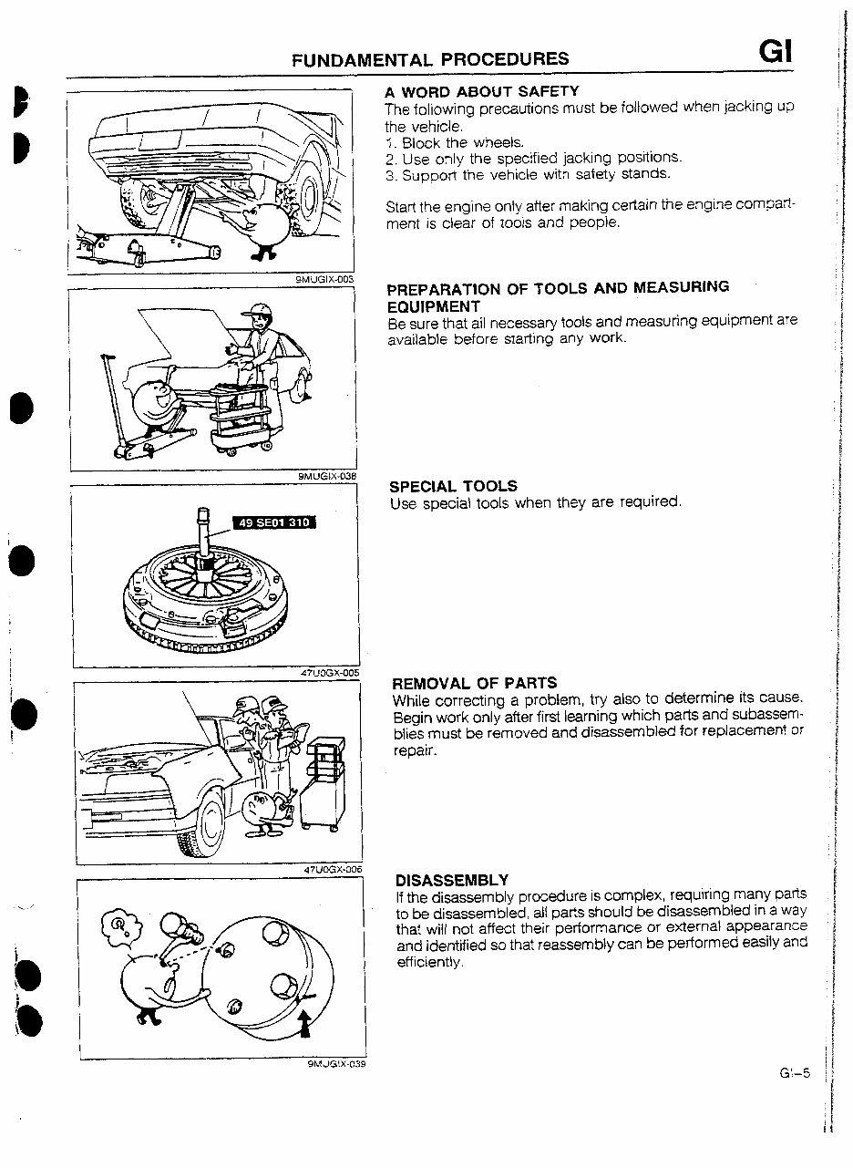
FUNDAMENTAL PROCEDURES GI I 9MUGIX-003 I SMUGIX-038 A WORD ABOUT SAFETY The following precautions must be followed when jacking up the vehicle, 3. Block the wheels. 2. Use only the specified jacking positions. 3. Support the vehicle with safety stands. Start the engine only after making certain the engine compart- ment is clear of tools and people. PREPARATION OF TOOLS AND MEASURING EQUIPMENT Be sure that all necessary tools and measuring equipment are available before starting any work. SPECIAL TOOLS Use special toots when they are required. REMOVAL OF PARTS White correcting a problem, try also to determine its cause. Begin work only after first learning which parts and subassem- blies must be removed and disassembled for replacement or repair. 1 47ilOGX-006 1 DISASSEMBLY If the disassembly procedure is complex, requiring many parts to be disassembled, all parts should be disassembled in a way that will not affect their performance or external appearance and identified so that reassembly can be performed easily and efficiently. t 9MlJGIX439
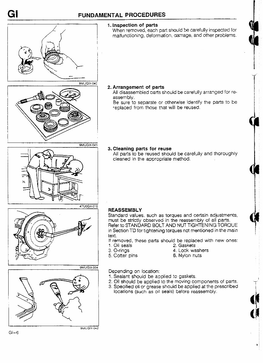
GI FUNDAMENTAL PROCEDURES 9MUGtX-040 SMLIGIX-041 SMUGIX-004 1. Inspection of parts When removed, each part should be carefully inspected for malfunctioning, deformation, damage, and other problems. 2. Arrangement of parts All disassembled parts should be carefully arranged for re- assembly. Be sure to separate or otherwise identify the parts to be replaced from those that will be reused. 3. Cleaning parts for reuse All parts to be reused should be carefully and thoroughly cleaned in the appropriate method. REASSEMBLY Standard values, such as torques and certain adjustments must be strictly observed in the reassembly of all parts. Refer to STANDARD BOLT AND NUT TIGHTENING TORQUE in Section TD for tightening torques not mentioned in the main text. If removed, these parts should be replaced with new ones: 1. Oil seals 2. Gaskets 3. O-rings 4. Lock washers 5. Cotter pins 6. Nylon nuts Depending on location: 1. Sealant should be applied to gaskets. 2. Oil should be applied to the moving components of parts. 3. Specified oil or grease should be applied at the prescribed locations (such as oil seals) before reassembly. ‘31-6
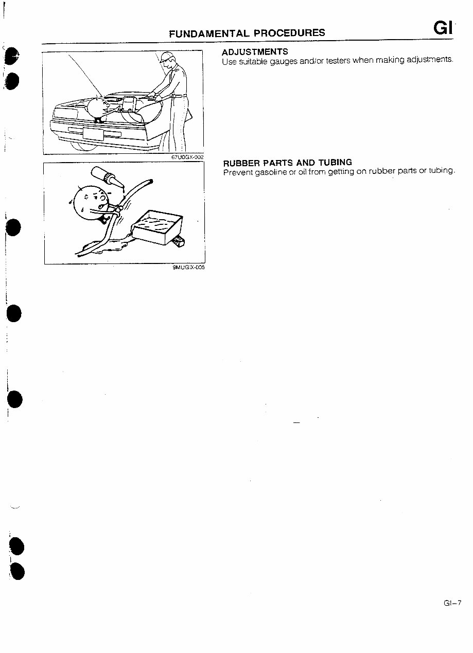
FUNDAMENTAL PROCEDURES GI’ I ADJUSTMENTS Use suitable gauges and/or testers when making adjustments. I 67UOGX-002 RUBBER PARTS AND TUBING Prevent gasoline or oil from getting on rubber parts or tubing. 5 Gl-7
This is a comprehensive Service/ Workshop Manual for the Mazda 323 GTR 1992. It contains detailed instructions and step-by-step diagrams for all workshop procedures, including engine rebuilding, plug replacement, electrical diagrams, torque settings, and fluid capacities. The manual also includes technical data, spare parts illustrations, and exploded view diagrams. Whether you are a professional mechanic or a DIY enthusiast, this manual provides valuable information for working on the Mazda 323 GTR 1992.
General Information
Engine
Injection-Ignition/Injection System
Clutch
Gearbox
Suspension System
Wheels
Braking System
Control Driving Instructions
Air Temp Control System
Electrical System
Bodywork
Exploded Views & Diagrams
And more...
All pages in this manual are printable, allowing you to have the necessary information at hand in your home, office, or repair shop. By following the easy-to-understand, step-by-step instructions, you can save money by performing your own repairs on the Mazda 323 GTR 1992.