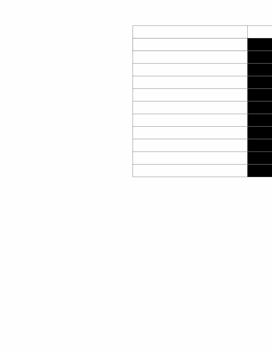
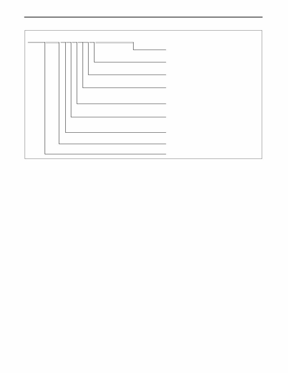
GENERAL INFORMATION 00-00–2 VEHICLE IDENTIFICATION NUMBER (VIN) CODE id000000100200 End Of Sie VEHICLE IDENTIFICATION NUMBER (VIN) id000000100300 JM3 ER29L*7# 100001— JM3 ER293*7# 100001— End Of Sie WM: GENERAL INFORMATION J M 3 E R 2 9 3 * 7 # 1 2 3 4 5 6 Model year Plant Serial No. 0= Hiroshima 1= Hofu 7= 2007 Engine Body, Gross vehicle weight class 9= Wagon, Gross vehicle weight class C (1814—2267 kg) Carline, Series ER= Mazda CX-7 JM3= Mazda/Multi-purpose vehicle category/U.S.A. World manufacturer identification Check digit *= 0 to 9, X L= 2.3 L (California (L3 WITH TC)) 3= 2.3 L (Federal/CANADA (L3 WITH TC)) Resraint system 2= with Curtain and Side air bags acxuuw00002316
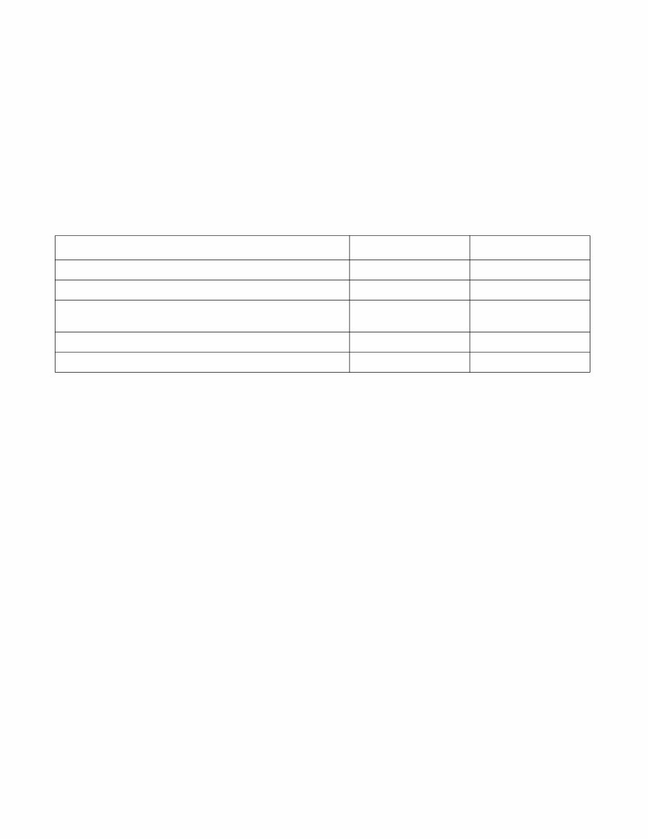
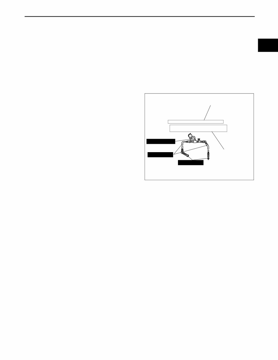
GENERAL INFORMATION 00-00–3 00-00 HOW TO USE THIS MANUAL id000000800100 Range of Topics • This manual contains procedures for performing all required service operations. The procedures are divided into the following five basic operations: — Removal/Installation — Disassembly/Assembly — Replacement — Inspection — Adjustment • Simple operations which can be performed easily just by looking at the vehicle (i.e., removal/installation of parts, jacking, vehicle lifting, cleaning of parts, and visual inspection) have been omitted. Service Procedure Inspection, adjustment • Inspection and adjustment procedures are divided into steps. Important points regarding the location and contents of the procedures are explained in detail and shown in the illustrations. 49 H002 671 49 H032 322 49 1232 670A SHOWS PROCEDURE ORDER FOR SERVICE Fluid Pressure Inspection 1. Assemble the SSTs as shown in the figure. Tightening torque SHOWS TIGHTENING TORQUE SPECIFICATIONS Caution Connect the gauge set from under the vehicle to prevent contact with the drive belt and the cooling fan. 39—49 N·m {4.0—5.0 kgf·m, 29—36 ft·lbf} acxuuw00000434
GENERAL INFORMATION 00-00–4 Repair procedure 1. Most repair operations begin with an overview illustration. It identifies the components, shows how the parts fit together, and describes visual part inspection. However, only removal/installation procedures that need to be performed methodically have written instructions. 2. Expendable parts, tightening torques, and symbols for oil, grease, and sealant are shown in the overview illustration. In addition, symbols indicating parts requiring the use of special service tools or equivalent are also shown. 3. Procedure steps are numbered and the part that is the main point of that procedure is shown in the illustration with the corresponding number. Occasionally, there are important points or additional information concerning a procedure. Refer to this information when servicing the related part. GREASE GREASE GREASE GREASE INDICATES RELEVANT REFERENCES THAT NEED TO BE FOLLOWED DURING INSTALLATION SHOWS SPECIAL SERVICE TOOL (SST) FOR SERVICE OPERATION SHOWS SPECIAL SERVICE TOOL (SST) NO. SHOWS TIGHTENING TORQUE SPECIFICATIONS SHOWS PROCEDURE ORDER FOR SERVICE SHOWS APPLICATION POINTS OF GREASE, ETC. SHOWS EXPENDABLE PARTS SHOWS DETAILS SHOWS TIGHTENING TORQUE UNITS KNUCKLE UPPER TRAILING LINK LOWER TRAILING LINK SST SST SST SST R R R R 9 2 1 4 5 3 6 1 2 8 7 12 10 11 N·m {kgf·m, ft·lbf} 118—156 {12.0—16.0, 87—115} 94—116 {9.5—11.9, 69—86} 44—60 {4.4—6.2, 32—44} 43—56 {4.3—5.8, 32—41} 49 T028 304 49 T028 305 49 T028 303 Procedure "Removal/Installation" Portion "Inspection After Installation" Portion INSTALL THE PARTS BY PERFORMING STEPS 1 3 IN REVERSE ORDER SHOWS REFERRAL NOTES FOR SERVICE SHOWS REFERRAL NOTES FOR SERVICE LOWER TRAILING LINK, UPPER TRAILING LINK REMOVAL/INSTALLATION 1. Jack up the rear of the vehicle and support it with safety stands. 2. Remove the undercover. (See 01-10-4 Undercover Removal) 3. Remove in the order indicated in the table. 4. Install in the reverse order of removal. 5. Inspect the rear wheel alignment and adjust it if necessary. SHOWS SERVICE ITEM (S) 1 Split pin 2 Nut 3 Lower trailing link ball joint 4 (See 02-14-5 Lower Trailing Link Ball Joint Removal Note) Bolt 5 Lower trailing link 6 Dust boot (lower trailing link) 7 Split pin 8 Nut 9 Upper trailing link ball joint (See 02-14-5 Upper Trailing Link Ball Joint Removal Note) 10 Nut 11 Upper trailing link 12 Dust boot (upper trailing link) Lower Trailing Link Ball Joint, Upper Trailing Link Ball Joint Removal Note Remove the ball joint using the SSTs. — acxuuw00000435
GENERAL INFORMATION 00-00–5 00-00 Symbols • There are eight symbols indicating oil, grease, fluids, sealant, and the use of SST or equivalent. use. These symbols show application points or use of these materials during service. Advisory Messages • You will find several Warnings, Cautions, Notes, Specifications and Upper and Lower Limits in this manual. Warning • A Warning indicates a situation in which serious injury or death could result if the warning is ignored. Caution • A Caution indicates a situation in which damage to the vehicle or parts could result if the caution is ignored. Note • A Note provides added information that will help you to complete a particular procedure. Specification • The values indicate the allowable range when performing inspections or adjustments. Upper and lower limits • The values indicate the upper and lower limits that must not be exceeded when performing inspections or adjustments. Symbol Meaning Kind Apply oil New appropriate engine oil or gear oil Apply brake fluid New appropriate brake fluid Apply automatic transaxle/ transmission fluid New appropriate automatic transaxle/ transmission fluid Apply grease Appropriate grease Apply sealant Appropriate sealant Apply petroleum jelly Appropriate petroleum jelly Replace part O-ring, gasket, etc. Use SST or equivalent Appropriate tools OIL BRAKE FLUID A ATF TF GREASE GREASE SEALANT P R SST
GENERAL INFORMATION 00-00–6 Troubleshooting Procedure Basic flow of troubleshooting DTC troubleshooting flow (on-board diagnostic) • Diagnostic trouble codes (DTCs) are important hints for repairing malfunctions that are difficult to simulate. Perform the specific DTC diagnostic inspection to quickly and accurately diagnose the malfunction. • The on-board diagnostic function is used during inspection. When a DTC is shown specifying the cause of a malfunction, continue the diagnostic inspection according to the items indicated by the on-board diagnostic function. Diagnostic index • The diagnostic index lists the symptoms of specific malfunctions. Select the symptoms related or most closely relating to the malfunction. Quick diagnosis chart (If mentioned) • The quick diagnosis chart lists diagnosis and inspection procedures to be performed specifically relating to the cause of the malfunction. Symptom troubleshooting • Symptom troubleshooting quickly determines the location of the malfunction according to symptom type. CUSTOMER ARRIVES DTC TABLE DTC NO WARNING LIGHT* WITH SYMPTOM CHECK DTC IGNITION ON TEST, IDLING TEST WITHOUT DTC DIAGNOSE BY SYMPTOM (SYMPTOM TROUBLESHOOTING) 1. DIAGNOSTIC INDEX 2. QUICK DIAGNOSIS CHART (IF MENTIONED) 3. SYMPTOM TROUBLESHOOTING *: INDICATOR LIGHTS AND WARNING LIGHTS THAT INDICATE MALFUNCTIONS DTC TROUBLESHOOTING FLOW DIAGNOSE BY DTC (ON-BOARD DIAGNOSTIC) WARNING LIGHT* ON/FLASHING CHECK FOR PRIORITIZED DTC acxuuw00000444
GENERAL INFORMATION 00-00–7 00-00 Procedures for Use Using the basic inspection (section 05) • Perform the basic inspection procedure before symptom troubleshooting. • Perform each step in the order shown. • The reference column lists the location of the detailed procedure for each basic inspection. • Although inspections and adjustments are performed according to the reference column procedures, if the cause of the malfunction is discovered during basic inspection, continue the procedures as indicated in the action column. BASIC INSPECTION STEP INSPECTION ACTION 1 2 3 4 5 Perform the stall test. (See 05-13-4 Stall Speed Test.) Is the stall speed normal? Yes Yes Yes Yes Yes No No No No No Go to the next step. Go to next step. Go to the next step. Go to the next step. Go to the next step. REFERENCE COLUMN SHOWS INSPECTION ORDER SHOWS ITEM NAMES FOR DETAILED PROCEDURES SHOW POINTS REQUIRING ATTENTION BASED ON INSPECTION RESULTS Repair or replace any malfunctioning parts according to the inspection result. Repair or replace any malfunctioning parts according to the inspection result. Flush ATX and cooler line as necessary. Repair or replace any malfunctioning parts according to the inspection result. Repair or replace any malfunctioning parts according to the inspection result. Perform the mechanical system test. (See 05-13-3 MECHANICAL SYSTEM TEST.) Is mechanical system normal? Inspect the ATF color condition. (See 05-13-8 AUTOMATIC TRANSMISSION FLUID (ATF) INSPECTION.) Are ATF color and odor normal? Perform the line pressure test. (See 05-13-3 Line Pressure Test.) Is the line pressure normal? Turn the ignition switch to the ON position. When the selector lever is moved, does the selector illumination indicate synchronized position to the lever location? Also, when other ranges are selected from N or P during idling, does the vehicle move within 1—2 s? Inspect the selector lever and TR switch. Repair or replace malfunctioning parts. (See 05-14-5 SELECTOR LEVER INSPECTION.) (See 05-13-10 TRANSMISSION RANGE (TR) SWITCH INSPECTION.) If the selector lever and TR switch are normal, go to the next step. Inspect the voltage at the following TCM terminals. (See 05-13-29 TCM INSPECTION.) Terminal 2J (TFT sensor) Terminals 1D, 2B, 2C, 2E (TR switch) Terminal 2G (turbine sensor) Terminal 2D (down switch) Terminal 2I (up switch) Terminal 1E (M range switch) Terminal 1W (steering shift switch) Is the voltage normal? Yes No Go to the next step. Repair or replace any malfunctioning parts according to the inspection result. acxuuw00000445
GENERAL INFORMATION 00-00–8 Using the DTC troubleshooting flow • DTC troubleshooting flow shows diagnostic procedures, inspection methods, and proper action to take for each DTC. B E D 36 88 4 4 4 7 5 6 6 POSSIBLE CAUSE 1 2 4 3 A B C D E 1P DTC P0103 DTC PO103 DETECTION CONDITION MAF sensor malfunction Connector or terminal malfunction Open circuit in wiring between MAF sensor terminal D and PCM terminal 36 Open circuit in MAF sensor ground circuit PCM MAF SENSOR MAF SENSOR HARNESS SIDE CONNECTOR PCM HARNESS SIDE CONNECTOR Diagnostic procedure STEP INSPECTION Has FREEZE FRAME DATA been recorded? VERIFY RELATED REPAIR INFORMATION AVAILABILITY Connect diagnostic tool to DLC-2. Start engine. Access MAF V PID using diagnostic tool. Is MAF V PID within 0.2 - 8.3 V? Turn ignition key to OFF. Disconnect MAF sensor connector. Are there any malfunctions? ACTION Go to next step. Yes No Yes No Yes No Yes If vehicle is not repaired, then go to next step. Go to next step. Go to next step. Repair or replace terminals, then go to Step 8. POSSIBLE CAUSE describes possible point(s) of malfunction Indicates the inspection step No. to be performed (01 and 05 section) STEP shows the order of troubleshooting INSPECTION describes the method to quickly determine the malfunctioning part(s). Reference item(s) to perform ACTION. ACTION describes the appropriate action to be taken according to the result (Yes/No) of the INSPECTION. Indicates the connector related to the inspection Indicates the circuit to be inspected (01 and 05 section) DETECTION CONDITION describes the condition under which the DTC is detected. Check for poor connection (damaged, pulled- out terminals, corrosion etc.). INSPECT POOR CONNECTION OF MAF SENSOR CONNECTOR VERIFY CURRENT INPUT SIGNAL STATUS IS CONCERN INTERMITTENT OR CONSTANT Are related Service Bulletins and/or on-line repair information available? VERIFY FREEZE FRAME DATA HAS BEEN RECORDED Record FREEZE FRAME DATA on repair order, then go to next step. Perform repair or diagnosis according to available repair information. Intermittent concern is existing. Go to INTERMITTENT CONCERNS TROUBLESHOOTING procedure. (See 01-03-33 INTERMITTENT CONCERN TROUBLESHOOTING) FROM MAIN RELAY TERMINAL D MIL illuminates if PCM detects the above malfunction during first drive cycle. Therefore, PENDING CODE is not available. FREEZE FRAME DATE is available. DTC is stored in the PCM memory. This is a continuous monitor (CCM). Diagnostic support note PCM monitors input voltage from TP sensor after ignition key is turned on. If input voltage at PCM terminal 68 is above 8.25 V, PCM determines that TP circuit has malfunction. MAF circuit high input TROUBLE CONDITION acxuuw00000446
This Mazda CX7 Service Repair Manual is a comprehensive guide for individuals interested in the technical aspects of this vehicle. It contains all the technical details directly from the manufacturer, offering complete information on the brand. Whether you are a professional mechanic or a DIY enthusiast, this manual is dedicated to both maintenance and repairs, providing valuable insights and know-how.
The manual includes various equipment, diagrams, and detailed information for diagnostics, repair, and maintenance of the Mazda CX7. It covers mechanical and technical specifications, introductory mechanics, equipment elevation, collisions, products and supplies, painting, as well as descriptions of various parts of the vehicle.
With instant access to this manual, you can easily print each section as needed. In the 21st century, it's essential to utilize the opportunity to access manuals without the need for printed books or waiting for shipping. This manual provides step-by-step instructions, along with access to pictures, diagrams, assembly, disassembly, cleaning, repairing, and maintenance of the Mazda CX7.
Take advantage of the unlimited information available on the internet and start immediately with just one click. Access everything you need without the hassle of waiting for printed manuals or paying for postage.