

2007-2009 Mazda Cx7 Service & Repair Manual
What's Included?
Fast Download Speeds
Online & Offline Access
Access PDF Contents & Bookmarks
Full Search Facility
Print one or all pages of your manual
Title Section
GENERAL INFORMATION 00
ENGINE 01
SUSPENSION 02
DRIVELINE/AXLE 03
BRAKES 04
TRANSMISSION/TRANSAXLE 05
STEERING 06
HEATER, VENTILATION &
AIR CONDITIONING (HVAC)
07
RESTRAINTS 08
BODY & ACCESSORIES 09
ALPHABETICAL INDEX AI
CONTENTS
2007
Mazda
CX-7
Workshop
Manual
FOREWORD
This manual contains on-vehicle service
and/or diagnosis procedures for the Mazda
CX-7.
For proper repair and maintenance,
a thorough familiarization with this manual is
important, and it should always be kept in a
handy place for quick and easy reference.
All the contents of this manual, including
drawings and specifications, are the latest
available at the time of printing.
As modifications affecting repair or
maintenance occur, relevant information
supplementary to this volume will be made
available at Mazda dealers. This manual
should be kept up-to-date.
Mazda Motor Corporation reserves the right
to alter the specifications and contents of
this manual without obligation or advance
notice.
All rights reserved. No part of this book may
be reproduced or used in any form or by any
means, electronic or mechanical—including
photocopying and recording and the use of
any kind of information storage and retrieval
system—without permission in writing.
Mazda Motor Corporation
HIROSHIMA, JAPAN
APPLICATION:
This manual is applicable to vehicles
beginning with the Vehicle Identification
Numbers (VIN), and related materials
shown on the following page.
© 2006 Mazda Motor Corporation
PRINTED IN U.S.A., FEBRUARY 2006
Form No. 1871–1U–06B
Part No. 9999–95–034B–07
VEHICLE IDENTIFICATION NUMBERS (VIN)
JM3 ER29L✻7# 100001—
JM3 ER293✻7# 100001—
RELATED MATERIALS
Material Name MNAO Part No. Mazda Material No.
Mazda CX-7 2007 Service Highlights 9999–95–045F–07 3416–1U–06B
Engine Workshop Manual L3 WITH TC 9999–95–0L3T–06 1833–1U–05H
Automatic Transaxle and Transfer Workshop Manual
AW6A-EL AW6AX-EL
9999–95–0AW6–07 1874–1U–06B
Mazda CX-7 Bodyshop Manual 9999–95–093F–07 3419–1U–06C
Mazda CX-7 2007 Wiring Diagram 9999–95–068G–07 5666–1U–06B
00
GENERAL INFORMATION
00-00–1
SECTION
00-00
Toc of SCT
GENERAL INFORMATION . . . . 00-00
Toc of SCT
00-00 GENERAL INFORMATION
VEHICLE IDENTIFICATION
NUMBER (VIN) CODE . . . . . . . . . . . . . . 00-00–2
VEHICLE IDENTIFICATION
NUMBER (VIN) . . . . . . . . . . . . . . . . . . . 00-00–2
HOW TO USE THIS MANUAL . . . . . . . . . 00-00–3
Range of Topics . . . . . . . . . . . . . . . . . . 00-00–3
Service Procedure . . . . . . . . . . . . . . . . 00-00–3
Symbols . . . . . . . . . . . . . . . . . . . . . . . . 00-00–5
Advisory Messages . . . . . . . . . . . . . . . . 00-00–5
Troubleshooting Procedure . . . . . . . . . . 00-00–6
Procedures for Use . . . . . . . . . . . . . . . . 00-00–7
UNITS . . . . . . . . . . . . . . . . . . . . . . . . . . . . 00-00–12
Conversion to SI Units
(Système International d'Unités) . . . . . 00-00–12
Rounding Off . . . . . . . . . . . . . . . . . . . . . 00-00–12
Upper and Lower Limits . . . . . . . . . . . . 00-00–12
SERVICE CAUTIONS . . . . . . . . . . . . . . . . 00-00–13
Protection of the Vehicle . . . . . . . . . . . . 00-00–13
Preparation of Tools and
Measuring Equipment . . . . . . . . . . . . . 00-00–13
Special Service Tools . . . . . . . . . . . . . . 00-00–13
Malfunction Diagnosis System . . . . . . . 00-00–13
Disconnection of the Negative
Battery Cable . . . . . . . . . . . . . . . . . . . 00-00–13
Oil Leakage Inspection . . . . . . . . . . . . . 00-00–14
Removal of Parts . . . . . . . . . . . . . . . . . . 00-00–14
Disassembly . . . . . . . . . . . . . . . . . . . . . 00-00–15
Inspection During Removal,
Disassembly . . . . . . . . . . . . . . . . . . . . 00-00–15
Arrangement of Parts . . . . . . . . . . . . . . 00-00–15
Cleaning of Parts. . . . . . . . . . . . . . . . . . 00-00–15
Reassembly . . . . . . . . . . . . . . . . . . . . . 00-00–16
Adjustment . . . . . . . . . . . . . . . . . . . . . . 00-00–16
Rubber Parts and Tubing . . . . . . . . . . . 00-00–16
Hose Clamps. . . . . . . . . . . . . . . . . . . . . 00-00–17
Torque Formulas . . . . . . . . . . . . . . . . . . 00-00–17
Vise . . . . . . . . . . . . . . . . . . . . . . . . . . . . 00-00–17
Dynamometer . . . . . . . . . . . . . . . . . . . . 00-00–17
AWD inspection/service . . . . . . . . . . . . 00-00–18
SST . . . . . . . . . . . . . . . . . . . . . . . . . . . 00-00–19
INSTALLATION OF
RADIO SYSTEM . . . . . . . . . . . . . . . . . . 00-00–20
ELECTRICAL SYSTEM. . . . . . . . . . . . . . 00-00–20
Electrical Parts . . . . . . . . . . . . . . . . . . . 00-00–20
Wiring Harness. . . . . . . . . . . . . . . . . . . 00-00–20
Connectors . . . . . . . . . . . . . . . . . . . . . . 00-00–21
Terminals . . . . . . . . . . . . . . . . . . . . . . . 00-00–22
Sensors, Switches, and Relays . . . . . . 00-00–23
Wiring Harness. . . . . . . . . . . . . . . . . . . 00-00–23
Fuse . . . . . . . . . . . . . . . . . . . . . . . . . . . 00-00–24
Viewing orientation for
Connectors . . . . . . . . . . . . . . . . . . . . . 00-00–24
Electrical Troubleshooting Tools . . . . . . 00-00–25
Precautions Before Welding . . . . . . . . . 00-00–26
JACKING POSITIONS, VEHICLE LIFT
(2 SUPPORTS) AND SAFETY STAND
(RIGID RACK) POSITIONS . . . . . . . . . 00-00–27
Jacking Positions . . . . . . . . . . . . . . . . . 00-00–27
Vehicle Lift Positions. . . . . . . . . . . . . . . 00-00–28
Safety Stand Positions . . . . . . . . . . . . . 00-00–28
TOWING . . . . . . . . . . . . . . . . . . . . . . . . . . 00-00–29
Towing a 2WD Vehicle . . . . . . . . . . . . . 00-00–29
Towing a AWD Vehicle . . . . . . . . . . . . . 00-00–30
Towing/Tiedown Hooks . . . . . . . . . . . . 00-00–30
TIEDOWN HOOK. . . . . . . . . . . . . . . . . . . 00-00–31
IDENTIFICATION NUMBER
LOCATIONS . . . . . . . . . . . . . . . . . . . . . 00-00–32
Vehicle Identification
Number (VIN) . . . . . . . . . . . . . . . . . . . 00-00–32
Engine Identification Number . . . . . . . . 00-00–32
SAE STANDARDS . . . . . . . . . . . . . . . . . . 00-00–33
ABBREVIATIONS . . . . . . . . . . . . . . . . . . 00-00–34
PRE-DELIVERY INSPECTION . . . . . . . . 00-00–35
Pre-Delivery Inspection Table. . . . . . . . 00-00–35
SCHEDULED MAINTENANCE . . . . . . . . 00-00–37
Scheduled Maintenance Table for U.S.A.,
CANADA and Puerto Rico . . . . . . . . . 00-00–37
End of Toc
NG: GENERAL INFORMATION
GENERAL INFORMATION
00-00–2
VEHICLE IDENTIFICATION NUMBER (VIN) CODE
id000000100200
End Of Sie
VEHICLE IDENTIFICATION NUMBER (VIN)
id000000100300
JM3 ER29L*7# 100001—
JM3 ER293*7# 100001—
End Of Sie
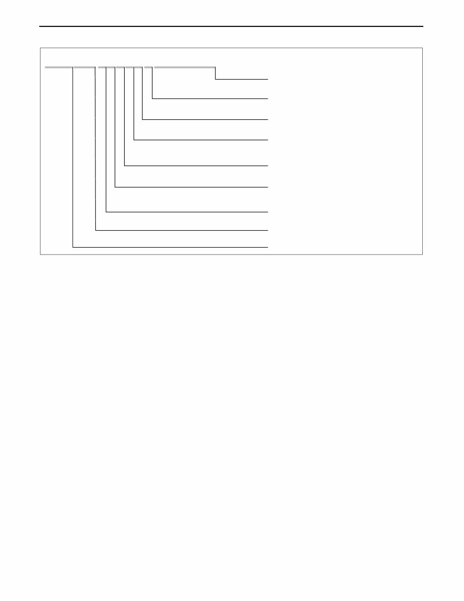
WM: GENERAL INFORMATION
J M 3 E R 2 9 3 * 7 # 1 2 3 4 5 6
Model year
Plant
Serial No.
0= Hiroshima
1= Hofu
7= 2007
Engine
Body, Gross vehicle weight class
9= Wagon, Gross vehicle weight class C
(1814—2267 kg)
Carline, Series
ER= Mazda CX-7
JM3= Mazda/Multi-purpose vehicle category/U.S.A. World manufacturer identification
Check digit
*= 0 to 9, X
L= 2.3 L (California (L3 WITH TC))
3= 2.3 L (Federal/CANADA (L3 WITH TC))
Resraint system 2= with Curtain and Side air bags
acxuuw00002316
GENERAL INFORMATION
00-00–3
00-00
HOW TO USE THIS MANUAL
id000000800100
Range of Topics
• This manual contains procedures for performing all required service operations. The procedures are divided
into the following five basic operations:
— Removal/Installation
— Disassembly/Assembly
— Replacement
— Inspection
— Adjustment
• Simple operations which can be performed easily just by looking at the vehicle (i.e., removal/installation of
parts, jacking, vehicle lifting, cleaning of parts, and visual inspection) have been omitted.
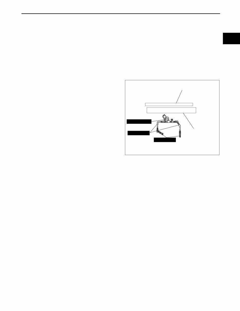
Service Procedure
Inspection, adjustment
• Inspection and adjustment procedures are
divided into steps. Important points regarding the
location and contents of the procedures are
explained in detail and shown in the illustrations.
49 H002 671
49 H032 322
49 1232 670A
SHOWS PROCEDURE ORDER
FOR SERVICE
Fluid Pressure Inspection
1. Assemble the SSTs as shown in the figure.
Tightening torque
SHOWS TIGHTENING
TORQUE
SPECIFICATIONS
Caution
Connect the gauge set from under
the vehicle to prevent contact with
the drive belt and the cooling fan.
39—49 N·m {4.0—5.0 kgf·m, 29—36 ft·lbf}
acxuuw00000434
GENERAL INFORMATION
00-00–4
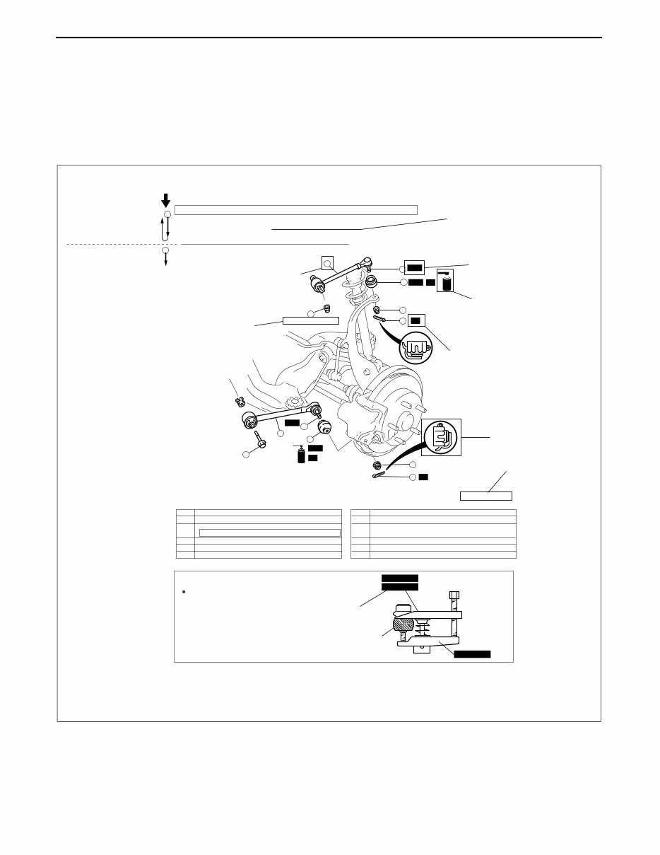
Repair procedure
1. Most repair operations begin with an overview illustration. It identifies the components, shows how the parts fit
together, and describes visual part inspection. However, only removal/installation procedures that need to be
performed methodically have written instructions.
2. Expendable parts, tightening torques, and symbols for oil, grease, and sealant are shown in the overview
illustration. In addition, symbols indicating parts requiring the use of special service tools or equivalent are also
shown.
3. Procedure steps are numbered and the part that is the main point of that procedure is shown in the illustration
with the corresponding number. Occasionally, there are important points or additional information concerning a
procedure. Refer to this information when servicing the related part.
GREASE GREASE
GREASE GREASE
INDICATES RELEVANT
REFERENCES THAT NEED
TO BE FOLLOWED DURING
INSTALLATION
SHOWS SPECIAL
SERVICE TOOL (SST)
FOR SERVICE OPERATION
SHOWS SPECIAL
SERVICE TOOL (SST)
NO.
SHOWS TIGHTENING
TORQUE
SPECIFICATIONS
SHOWS PROCEDURE ORDER
FOR SERVICE
SHOWS APPLICATION
POINTS OF GREASE, ETC.
SHOWS EXPENDABLE PARTS
SHOWS DETAILS
SHOWS TIGHTENING
TORQUE UNITS
KNUCKLE
UPPER TRAILING LINK
LOWER TRAILING LINK
SST
SST
SST
SST
R
R
R
R
9
2
1
4
5
3
6
1
2
8
7
12
10
11
N·m {kgf·m, ft·lbf}
118—156 {12.0—16.0, 87—115}
94—116 {9.5—11.9, 69—86}
44—60 {4.4—6.2, 32—44}
43—56 {4.3—5.8, 32—41}
49 T028 304
49 T028 305
49 T028 303
Procedure
"Removal/Installation"
Portion
"Inspection After
Installation" Portion
INSTALL THE PARTS BY
PERFORMING STEPS
1 3 IN REVERSE ORDER
SHOWS REFERRAL
NOTES FOR SERVICE
SHOWS REFERRAL
NOTES FOR
SERVICE
LOWER TRAILING LINK, UPPER TRAILING LINK REMOVAL/INSTALLATION
1. Jack up the rear of the vehicle and support it with safety stands.
2. Remove the undercover. (See 01-10-4 Undercover Removal)
3. Remove in the order indicated in the table.
4. Install in the reverse order of removal.
5. Inspect the rear wheel alignment and adjust it if necessary.
SHOWS SERVICE
ITEM (S)
1 Split pin
2
Nut
3
Lower trailing link ball joint
4
(See 02-14-5 Lower Trailing Link Ball Joint Removal Note)
Bolt
5 Lower trailing link
6 Dust boot (lower trailing link)
7 Split pin
8 Nut
9 Upper trailing link ball joint
(See 02-14-5 Upper Trailing Link Ball Joint Removal Note)
10 Nut
11 Upper trailing link
12 Dust boot (upper trailing link)
Lower Trailing Link Ball Joint, Upper Trailing Link
Ball Joint Removal Note
Remove the ball joint using the SSTs.
—
acxuuw00000435
GENERAL INFORMATION
00-00–5
00-00
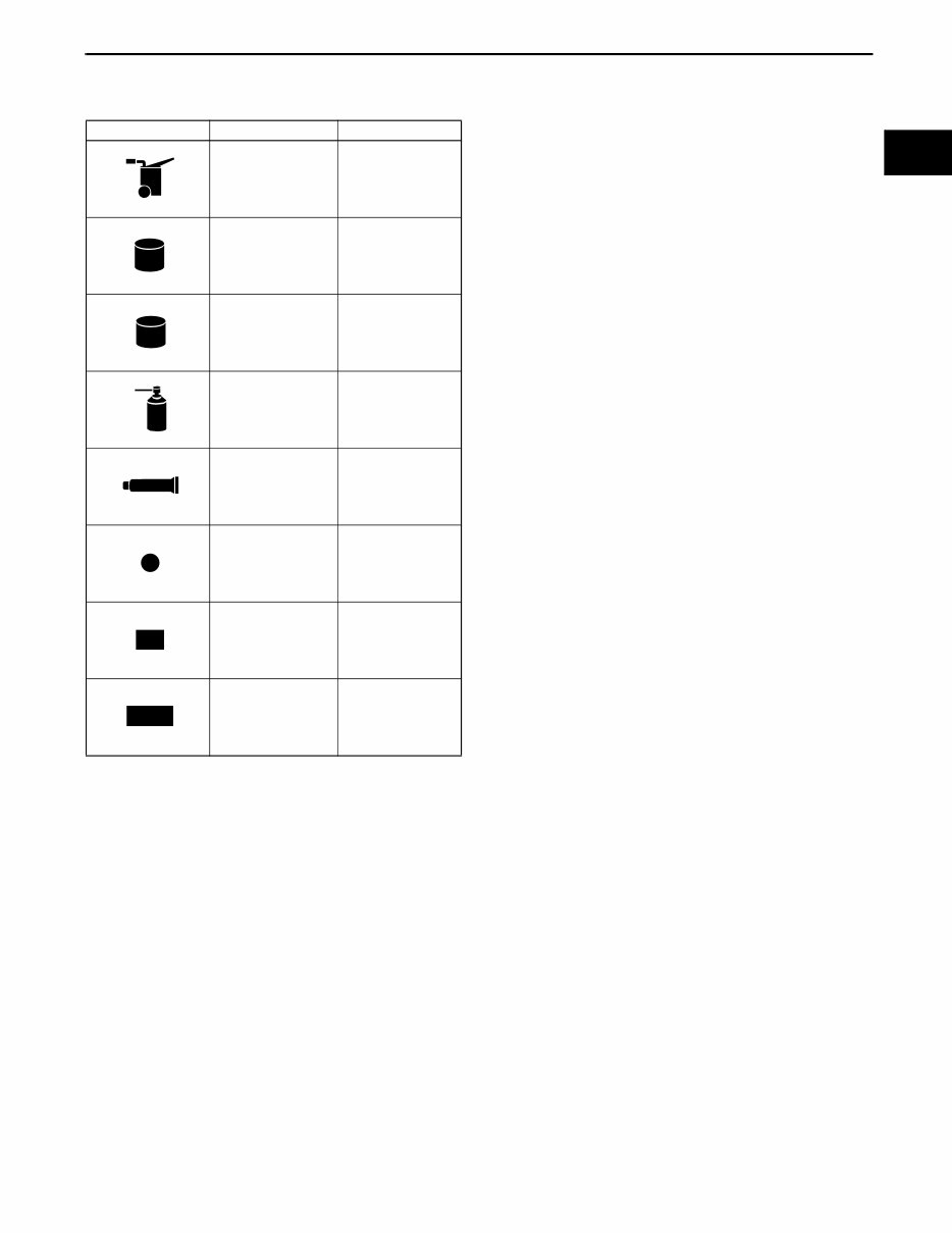
Symbols
• There are eight symbols indicating oil, grease, fluids, sealant, and the use of SST or equivalent. use. These
symbols show application points or use of these materials during service.
Advisory Messages
• You will find several Warnings, Cautions, Notes, Specifications and Upper and Lower Limits in this
manual.
Warning
• A Warning indicates a situation in which serious injury or death could result if the warning is ignored.
Caution
• A Caution indicates a situation in which damage to the vehicle or parts could result if the caution is ignored.
Note
• A Note provides added information that will help you to complete a particular procedure.
Specification
• The values indicate the allowable range when performing inspections or adjustments.
Upper and lower limits
• The values indicate the upper and lower limits that must not be exceeded when performing inspections or
adjustments.
Symbol Meaning Kind
Apply oil
New appropriate
engine oil or gear
oil
Apply brake fluid
New appropriate
brake fluid
Apply automatic
transaxle/
transmission fluid
New appropriate
automatic
transaxle/
transmission fluid
Apply grease
Appropriate
grease
Apply sealant
Appropriate
sealant
Apply petroleum
jelly
Appropriate
petroleum jelly
Replace part
O-ring, gasket,
etc.
Use SST or
equivalent
Appropriate tools
OIL
BRAKE
FLUID
A ATF TF
GREASE GREASE
SEALANT
P
R
SST
GENERAL INFORMATION
00-00–6
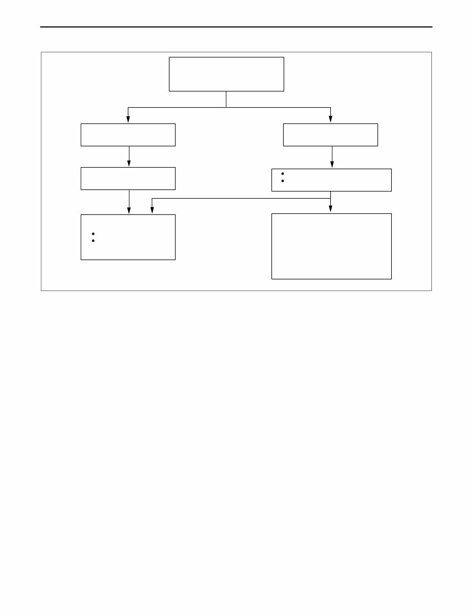
Troubleshooting Procedure
Basic flow of troubleshooting
DTC troubleshooting flow (on-board diagnostic)
• Diagnostic trouble codes (DTCs) are important hints for repairing malfunctions that are difficult to simulate.
Perform the specific DTC diagnostic inspection to quickly and accurately diagnose the malfunction.
• The on-board diagnostic function is used during inspection. When a DTC is shown specifying the cause of a
malfunction, continue the diagnostic inspection according to the items indicated by the on-board diagnostic
function.
Diagnostic index
• The diagnostic index lists the symptoms of specific malfunctions. Select the symptoms related or most closely
relating to the malfunction.
Quick diagnosis chart (If mentioned)
• The quick diagnosis chart lists diagnosis and inspection procedures to be performed specifically relating to the
cause of the malfunction.
Symptom troubleshooting
• Symptom troubleshooting quickly determines the location of the malfunction according to symptom type.
CUSTOMER ARRIVES
DTC TABLE
DTC
NO WARNING LIGHT*
WITH SYMPTOM
CHECK DTC
IGNITION ON TEST, IDLING
TEST
WITHOUT DTC
DIAGNOSE BY SYMPTOM
(SYMPTOM TROUBLESHOOTING)
1. DIAGNOSTIC INDEX
2. QUICK DIAGNOSIS CHART
(IF MENTIONED)
3. SYMPTOM
TROUBLESHOOTING
*: INDICATOR LIGHTS AND WARNING
LIGHTS THAT INDICATE MALFUNCTIONS
DTC
TROUBLESHOOTING
FLOW
DIAGNOSE BY DTC
(ON-BOARD DIAGNOSTIC)
WARNING LIGHT*
ON/FLASHING
CHECK FOR
PRIORITIZED DTC
acxuuw00000444
GENERAL INFORMATION
00-00–7
00-00
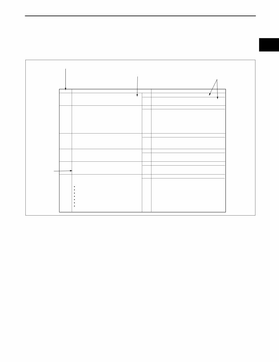
Procedures for Use
Using the basic inspection (section 05)
• Perform the basic inspection procedure before symptom troubleshooting.
• Perform each step in the order shown.
• The reference column lists the location of the detailed procedure for each basic inspection.
• Although inspections and adjustments are performed according to the reference column procedures, if the
cause of the malfunction is discovered during basic inspection, continue the procedures as indicated in the
action column.
BASIC INSPECTION
STEP INSPECTION ACTION
1
2
3
4
5 Perform the stall test.
(See 05-13-4 Stall Speed Test.)
Is the stall speed normal?
Yes
Yes
Yes
Yes
Yes
No
No
No
No
No
Go to the next step.
Go to next step.
Go to the next step.
Go to the next step.
Go to the next step.
REFERENCE
COLUMN
SHOWS INSPECTION
ORDER
SHOWS ITEM NAMES FOR
DETAILED PROCEDURES
SHOW POINTS REQUIRING
ATTENTION BASED ON
INSPECTION RESULTS
Repair or replace any malfunctioning parts according to
the inspection result.
Repair or replace any malfunctioning parts according to
the inspection result.
Flush ATX and cooler line as necessary.
Repair or replace any malfunctioning parts according to
the inspection result.
Repair or replace any malfunctioning parts according to
the inspection result.
Perform the mechanical system test.
(See 05-13-3 MECHANICAL SYSTEM TEST.)
Is mechanical system normal?
Inspect the ATF color condition.
(See 05-13-8 AUTOMATIC TRANSMISSION
FLUID (ATF) INSPECTION.)
Are ATF color and odor normal?
Perform the line pressure test.
(See 05-13-3 Line Pressure Test.)
Is the line pressure normal?
Turn the ignition switch to the ON position.
When the selector lever is moved, does the selector
illumination indicate synchronized position to the
lever location? Also, when other ranges are selected
from N or P during idling, does the vehicle move
within 1—2 s?
Inspect the selector lever and TR switch. Repair or
replace malfunctioning parts.
(See 05-14-5 SELECTOR LEVER INSPECTION.)
(See 05-13-10 TRANSMISSION RANGE (TR) SWITCH
INSPECTION.)
If the selector lever and TR switch are normal, go to the
next step.
Inspect the voltage at the following TCM terminals.
(See 05-13-29 TCM INSPECTION.)
Terminal 2J (TFT sensor)
Terminals 1D, 2B, 2C, 2E (TR switch)
Terminal 2G (turbine sensor)
Terminal 2D (down switch)
Terminal 2I (up switch)
Terminal 1E (M range switch)
Terminal 1W (steering shift switch)
Is the voltage normal?
Yes
No
Go to the next step.
Repair or replace any malfunctioning parts according to
the inspection result.
acxuuw00000445
GENERAL INFORMATION
00-00–8
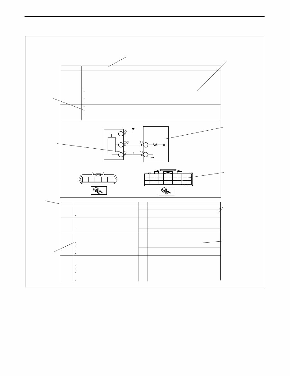
Using the DTC troubleshooting flow
• DTC troubleshooting flow shows diagnostic procedures, inspection methods, and proper action to take for each
DTC.
B
E
D 36
88
4
4
4
7
5 6
6
POSSIBLE
CAUSE
1
2
4
3
A B C D E
1P
DTC P0103
DTC PO103
DETECTION
CONDITION
MAF sensor malfunction
Connector or terminal malfunction
Open circuit in wiring between MAF sensor terminal D and PCM terminal 36
Open circuit in MAF sensor ground circuit
PCM
MAF SENSOR
MAF SENSOR
HARNESS SIDE CONNECTOR
PCM
HARNESS SIDE CONNECTOR
Diagnostic procedure
STEP INSPECTION
Has FREEZE FRAME DATA been recorded?
VERIFY RELATED REPAIR INFORMATION
AVAILABILITY
Connect diagnostic tool to DLC-2.
Start engine.
Access MAF V PID using diagnostic tool.
Is MAF V PID within 0.2 - 8.3 V?
Turn ignition key to OFF.
Disconnect MAF sensor connector.
Are there any malfunctions?
ACTION
Go to next step. Yes
No
Yes
No
Yes
No
Yes
If vehicle is not repaired, then go to next step.
Go to next step.
Go to next step.
Repair or replace terminals, then go to Step 8.
POSSIBLE
CAUSE
describes
possible
point(s) of
malfunction
Indicates the
inspection step
No. to be
performed
(01 and 05
section)
STEP shows
the order of
troubleshooting
INSPECTION
describes the
method to
quickly
determine the
malfunctioning
part(s).
Reference
item(s) to
perform
ACTION.
ACTION
describes the
appropriate
action to be taken
according to
the result
(Yes/No) of the
INSPECTION.
Indicates the
connector
related to the
inspection
Indicates the
circuit to be
inspected
(01 and 05
section)
DETECTION CONDITION
describes the condition
under which the DTC is
detected.
Check for poor connection (damaged, pulled-
out terminals, corrosion etc.).
INSPECT POOR CONNECTION OF MAF
SENSOR CONNECTOR
VERIFY CURRENT INPUT SIGNAL STATUS IS
CONCERN INTERMITTENT OR CONSTANT
Are related Service Bulletins and/or on-line
repair information available?
VERIFY FREEZE FRAME DATA HAS BEEN
RECORDED
Record FREEZE FRAME DATA on repair order, then go
to next step.
Perform repair or diagnosis according to available repair
information.
Intermittent concern is existing. Go to INTERMITTENT
CONCERNS TROUBLESHOOTING procedure.
(See 01-03-33 INTERMITTENT CONCERN
TROUBLESHOOTING)
FROM
MAIN RELAY
TERMINAL D
MIL illuminates if PCM detects the above malfunction during first drive cycle. Therefore,
PENDING CODE is not available.
FREEZE FRAME DATE is available.
DTC is stored in the PCM memory.
This is a continuous monitor (CCM).
Diagnostic support note
PCM monitors input voltage from TP sensor after ignition key is turned on. If input voltage at PCM terminal 68 is
above 8.25 V, PCM determines that TP circuit has malfunction.
MAF circuit high input
TROUBLE CONDITION
acxuuw00000446
You're Reading a Preview
What's Included?
Fast Download Speeds
Online & Offline Access
Access PDF Contents & Bookmarks
Full Search Facility
Print one or all pages of your manual
$27.99
Viewed 41 Times Today


Secure transaction
What's Included?
Fast Download Speeds
Online & Offline Access
Access PDF Contents & Bookmarks
Full Search Facility
Print one or all pages of your manual
$27.99
The Mazda CX-7 2007-2008-2009 Service repair manual provides comprehensive coverage for repairing and maintaining your vehicle. It is designed to be useful for both professional mechanics and DIY enthusiasts.
This manual is available in PDF format, allowing for easy reading, zooming, and printouts. It is compatible with any Windows operating system, ensuring accessibility for a wide range of users.


