


BACK TO MODEL INDEX
FOREWORD
This wiring diagram incorporates the wiring schematics of the Mazda CX-5 and available optional
equipment. Actual vehicle wiring may vary slightly depending on optional equipment or local specifications,
or both.
For proper repair and maintenance, a thorough familiarization with this manual is important, and it should
always be kept in a handy place for quick and easy reference.
All the contents of this manual, including drawings and specifications, are the latest available at the time of
printing.
As modifications affecting repair or maintenance occur, relevant information supplementary to this volume
will be made available at Mazda dealers. This manual should be kept up-to-date.
Ford Motor Company reserves the right to alter the specifications and contents of this manual without
obligation or advance notice.
All rights reserved. No part of this book may be reproduced or used in any form or by any means, electronic
or mechanical-including photocopying and recording and the use of any kind of information storage and
retrieval system-without permission in writing.
WARNING
Servicing a vehicle can be dangerous. If you have not received service-related training, the risks of
injury, property damage, and failure of servicing increase. The recommended servicing procedures
for the vehicle in this workshop manual were developed with Mazda-trained technicians in mind.
This manual may be useful to non-Mazda trained technicians, but a technician with our service-
related training and experience will be at less risk when performing service operations. However, all
users of this manual are accepted at least to know general safety procedures.
This manual contains “Warnings” and “Cautions” applicable to risks not normally encountered in a
general technician’s experience. They should be followed to reduce the risk of injury and the risk
that improper service or repair may damage the vehicle or render it unsafe. It is also important to
understand that the “Warnings” and “Cautions” are not exhaustive. It is impossible to warn of all the
hazardous consequences that might result from failure to follow the procedures.
The procedures recommended and described in this manual are effective methods of performing
service and repair. Some require tools specifically designed for a specific purpose. Persons using
procedures and tools which are not recommended by Mazda Motor Corporation must satisfy
themselves thoroughly that neither personal safety nor safety of the vehicle will be jeopardized.
The contents of this manual, including drawings and specifications, are the latest available at the
time of printing, and Mazda Motor Corporation reserves the right to change the vehicle designs and
alter the contents of this manual without notice and without incurring obligation.
Parts should be replaced with genuine Mazda replacement parts or with parts which match the
quality of genuine Mazda replacement parts. Persons using replacement parts of lesser quality than
that of genuine Mazda replacement parts must satisfy themselves thoroughly that neither personal
safety nor safety of the vehicle will be jeopardized. Mazda Motor Corporation is not responsible for
any problems which may arise from the use of this manual. The cause of such problems includes
but is not limited to insufficient service related training, use of improper tools, use of replacement
parts of lesser quality than that of genuine Mazda replacement parts, or not being aware of any
revision of this manual.
VIEW CONTENTS PAGE
Ford Motor Company
of Southern Africa
© 2012 FMCSA
MAZDA CX5 WORKSHOP REPAIR MANUAL
CONTENTS
Title Section
TO MODEL INDEX
APPLICATION:
This manual is applicable to vehicles beginning with
the Vehicle Identification Numbers (VIN) shown on
the following page.
© 2012 Ford Motor Company of Southern Africa
Workshop Repair
Manual
BACK TO FOREWORD & FRONT PAGE
GENERAL INFORMATION 00
ENGINE 01
SUSPENSION 02
DRIVELINE/AXLE 03
BRAKES 04
TRANSMISSION/
TRANSAXLE 05
STEERING 06
HEATER, VENTILATION &
AIR CONDITIONING (HVAC) 07
RESTRAINTS 08
BODY & ACCESSORIES 09
MULTIPLEX TEM
COMMUNICATION SYSTEM 10
I-STOP 11
PERSONALIZATION FEATURES 12
MAZDA CX5 WORKSHOP REPAIR MANUAL
00
GENERAL INFORMATION
SECTION
00
Toc of SCT
GENERAL INFORMATION . . . 00-00
Toc of SCT
TO MODEL INDEX
BACK TO MAIN INDEX MAZDA CX5 WORKSHOP REPAIR MANUAL

TO MODEL INDEX
BACK TO CHAPTER INDEX
00-00–1
00-00 GENERAL INFORMATION
VEHICLE IDENTIFICATION
NUMBER (VIN) CODE. . . . . . . . . . . . . . 00-00–2
European (L.H.D. U.K.)
China specs. . . . . . . . . . . . . . . . . . . . 00-00–2
Australian, General
(R.H.D.) specs. . . . . . . . . . . . . . . . . . . 00-00–2
General (L.H.D.) specs. . . . . . . . . . . . . 00-00–3
VEHICLE IDENTIFICATION
NUMBER (VIN) . . . . . . . . . . . . . . . . . . . 00-00–4
European (L.H.D. U.K.) specs. . . . . . . . 00-00–4
Australian, General (R.H.D.) specs. . . . 00-00–4
General (L.H.D.) specs. . . . . . . . . . . . . 00-00–4
HOW TO USE THIS MANUAL. . . . . . . . . 00-00–5
Range of Topics . . . . . . . . . . . . . . . . . . 00-00–5
Advisory Messages . . . . . . . . . . . . . . . 00-00–5
Symbols . . . . . . . . . . . . . . . . . . . . . . . . 00-00–5
Service Procedure . . . . . . . . . . . . . . . . 00-00–6
Troubleshooting Procedure . . . . . . . . . 00-00–8
Procedures for Use . . . . . . . . . . . . . . . 00-00–9
SERVICE CAUTIONS . . . . . . . . . . . . . . . 00-00–13
Injury/damage
Prevention Precautions . . . . . . . . . . . 00-00–13
Protection of the Vehicle . . . . . . . . . . . 00-00–13
Preparation of Tools and
Measuring Equipment . . . . . . . . . . . . 00-00–14
Special Service Tools . . . . . . . . . . . . . . 00-00–14
Malfunction Diagnosis System . . . . . . . 00-00–14
Oil Leakage Inspection . . . . . . . . . . . . 00-00–15
Negative Battery Cable
Disconnection/Connection . . . . . . . . . 00-00–16
Switch The Power Supply Using The
Push Button Start And
Start The Engine . . . . . . . . . . . . . . . . 00-00–17
Removal of Parts . . . . . . . . . . . . . . . . . 00-00–18
Control Unit Configuration
(Initial Setting) Procedure
Using M-MDS. . . . . . . . . . . . . . . . . . . 00-00–18
Disassembly . . . . . . . . . . . . . . . . . . . . . 00-00–18
Inspection During
Removal, Disassembly. . . . . . . . . . . . 00-00–19
Arrangement of Parts . . . . . . . . . . . . . . 00-00–19
Cleaning of Parts . . . . . . . . . . . . . . . . . 00-00–19
Reassembly . . . . . . . . . . . . . . . . . . . . . 00-00–19
Adjustment . . . . . . . . . . . . . . . . . . . . . . 00-00–20
Rubber Parts and Tubing . . . . . . . . . . . 00-00–20
Hose Clamps . . . . . . . . . . . . . . . . . . . . 00-00–20
Torque Formulas . . . . . . . . . . . . . . . . . 00-00–21
Vise . . . . . . . . . . . . . . . . . . . . . . . . . . . 00-00–21
Dynamometer . . . . . . . . . . . . . . . . . . . . 00-00–21
SST . . . . . . . . . . . . . . . . . . . . . . . . . . . . 00-00–22
INSTALLATION OF RADIO SYSTEM . . . 00-00–23
ELECTRICAL SYSTEM . . . . . . . . . . . . . . 00-00–24
Electrical Parts . . . . . . . . . . . . . . . . . . . 00-00–24
Wiring Harness . . . . . . . . . . . . . . . . . . . 00-00–24
Connectors . . . . . . . . . . . . . . . . . . . . . . 00-00–24
Terminals . . . . . . . . . . . . . . . . . . . . . . . . 00-00–26
Sensors, Switches, and Relays . . . . . . . 00-00–27
Wiring Harness . . . . . . . . . . . . . . . . . . . 00-00–27
Fuse . . . . . . . . . . . . . . . . . . . . . . . . . . . 00-00–27
Viewing orientation for Connectors . . . . 00-00–28
Electrical Troubleshooting Tools . . . . . . 00-00–29
Precautions Before Welding . . . . . . . . . 00-00–30
JACKING POSITIONS, VEHICLE LIFT
(2 SUPPORTS) AND SAFETY STAND
(RIGID RACK) POSITIONS . . . . . . . . . . 00-00–31
Jacking Positions . . . . . . . . . . . . . . . . . . 00-00–31
Vehicle Lift Positions . . . . . . . . . . . . . . . 00-00–32
TOWING . . . . . . . . . . . . . . . . . . . . . . . . . . 00-00–32
Towing Hooks . . . . . . . . . . . . . . . . . . . . 00-00–33
TIEDOWN HOOK . . . . . . . . . . . . . . . . . . . 00-00–35
IDENTIFICATION
NUMBER LOCATIONS. . . . . . . . . . . . . . 00-00–36
Vehicle Identification Number (VIN) . . . 00-00–36
Engine Identification Type/Number . . . . 00-00–36
UNITS . . . . . . . . . . . . . . . . . . . . . . . . . . . . 00-00–37
Conversion From SI Units . . . . . . . . . . . 00-00–37
Number Of Digits For
Converted Values . . . . . . . . . . . . . . . . 00-00–37
Converted Value Rounding Off
And Rounding Up/down . . . . . . . . . . . 00-00–37
NEW STANDARDS . . . . . . . . . . . . . . . . . . 00-00–38
ABBREVIATIONS . . . . . . . . . . . . . . . . . . . 00-00–40
PRE-DELIVERY INSPECTION . . . . . . . . . 00-00–41
Pre-Delivery Inspection Table . . . . . . . . 00-00–41
SCHEDULED MAINTENANCE . . . . . . . . 00-00–43
Scheduled Maintenance Table
for Europe (L.H.D., U.K.) . . . . . . . . . . . 00-00–43
Scheduled Maintenance
Table for Australia . . . . . . . . . . . . . . . . 00-00–45
Scheduled Maintenance
Table for General . . . . . . . . . . . . . . . . . 00-00–47
Scheduled Maintenance Table for
Russia/Belarus/Azerbaijan . . . . . . . . . 00-00–49
Scheduled Maintenance Service
(Specific Work Required) . . . . . . . . . . 00-00–51
End of Toc
NG: GENERAL INFORMATION
GENERAL INFORMATION
MAZDA CX5 WORKSHOP REPAIR MANUAL
00-00–2
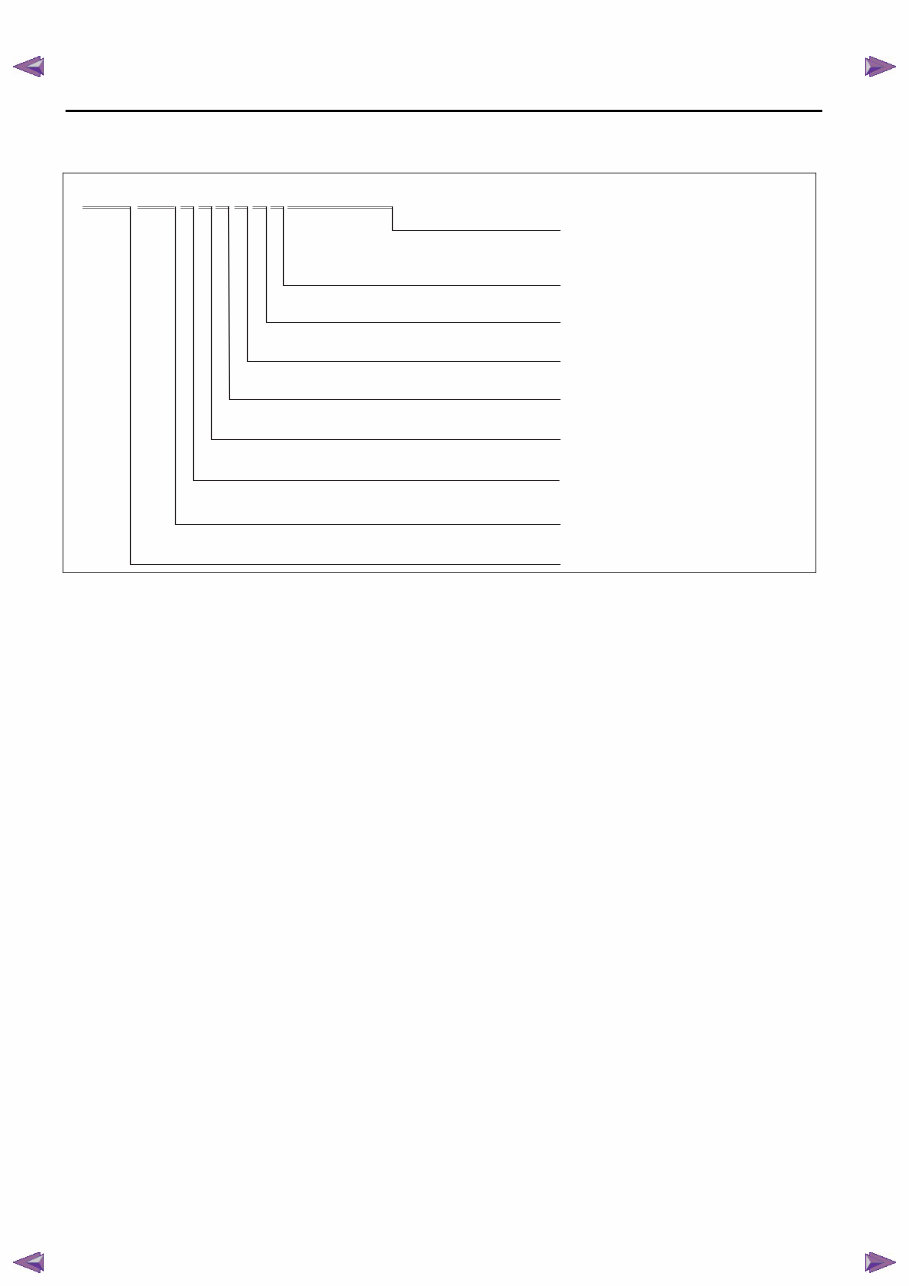
VEHICLE IDENTIFICATION NUMBER (VIN) CODE
id000000100200
Australian, General (R.H.D.) specs.
J M 0 K E 1 0 7 1 0 0 1 2 3 4 5 6
Dummy
Dummy
Serial No.
0
Minor change code 1
Engine
Dummy 0
KE= Mazda CX-5
JM6= Mazda (General (R.H.D.) specs.) World manufacturer identification
7= 2.0 L (SKYACTIV-G 2.0)
0
Body 1= Closed body
Carline and Series
2= 2.2 L (SKYACTIV-D 2.2 Hi, Diesel)
JM0= Mazda (Australian specs.)
ac5wzw0000464
TO MODEL INDEX
BACK TO CHAPTER INDEX
GENERAL INFORMATION
MAZDA CX5 WORKSHOP REPAIR MANUAL
00-00–4
GENERAL INFORMATION
VEHICLE IDENTIFICATION NUMBER (VIN)
id000000100300
Australian, General (R.H.D.) specs.
General (L.H.D.) specs.
Except for Algeria
Algeria only
End Of Sie
JM0 KE102100 100001—
JM0 KE107100 100001—
JM6 KE1071*0# 100001—
ac5wzw0000458
JMZ KEC978*# 100001—
JMZ KEK978*# 100001—
JM8 KE2W7**# 100001—
JM8 KE4W7**# 100001—
ac5wzw0000458
KE1071 100001 — m m
: This mark is used only for Algerian model, in order to identify the manufacturer. m
m
ac5wzw0000458
TO MODEL INDEX
BACK TO CHAPTER INDEX MAZDA CX5 WORKSHOP REPAIR MANUAL
GENERAL INFORMATION
00-00–5
00
HOW TO USE THIS MANUAL
id000000800100
Range of Topics
This manual contains procedures for performing all required service operations. The procedures are divided
into the following five basic operations:
— Removal/Installation
— Disassembly/Assembly
— Replacement
— Inspection
— Adjustment
Simple operations which can be performed easily just by looking at the vehicle (i.e., removal/installation of
parts, jacking, vehicle lifting, cleaning of parts, and visual inspection) have been omitted.
Advisory Messages
You will find several Warnings, Cautions, Notes, Specifications and Upper and Lower Limits in this
manual.
Warning
— A Warning indicates a situation in which serious injury or death could result if the warning is ignored.
Caution
— A Caution indicates a situation in which damage to the vehicle or parts could result if the caution is ignored.
Note
— A Note provides added information that will help you to complete a particular procedure.
Specification
— The values indicate the allowable range when performing inspections or adjustments.
Upper and lower limits
— The values indicate the upper and lower limits that must not be exceeded when performing inspections or
adjustments.
Symbols
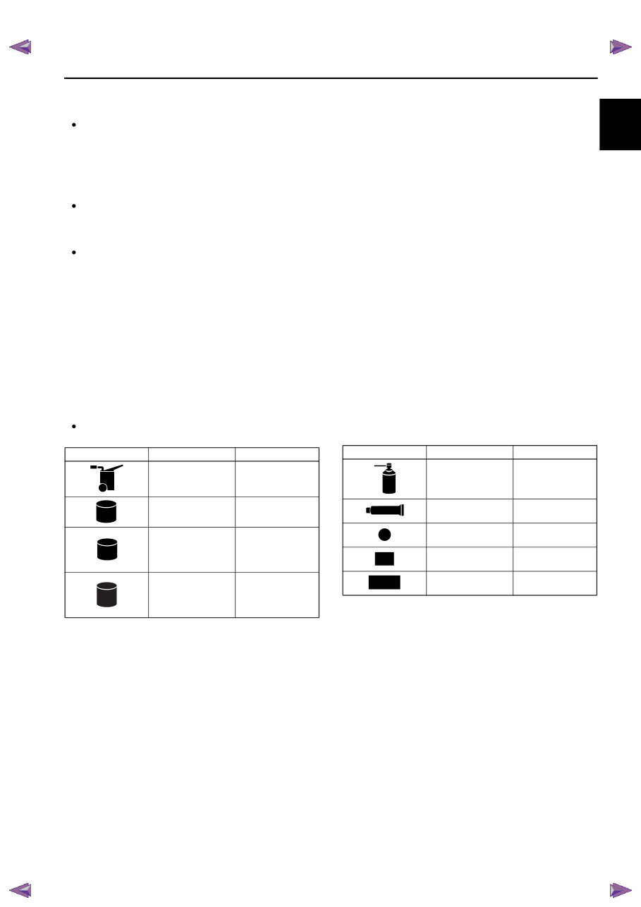
There are nine symbols indicating oil, grease, fluids, sealant, and the use of SST or equivalent. These symbols
show application points or use of these materials during service.
Symbol Meaning Kind
Apply oil
New appropriate
engine oil or gear
oil
Apply brake fluid
New appropriate
brake fluid
Apply automatic
transmission/
transaxle fluid
New appropriate
automatic
transmission/
transaxle fluid
Apply continuously
variable transaxle
fluid
New appropriate
continuously
variable transaxle
fluid
OIL
BRAKE
FLUID
ATF
CVT CVT
FLUID FLUID
Apply grease
Appropriate
grease
Apply sealant
Appropriate
sealant
Apply petroleum
jelly
Appropriate
petroleum jelly
Replace part
O-ring, gasket,
etc.
Use SST or
equivalent
Appropriate tools
Symbol Meaning Kind
GREASE
SEALANT
P
R
SST
TO MODEL INDEX
BACK TO CHAPTER INDEX MAZDA CX5 WORKSHOP REPAIR MANUAL
00-00–6
GENERAL INFORMATION
Service Procedure
Inspection, adjustment
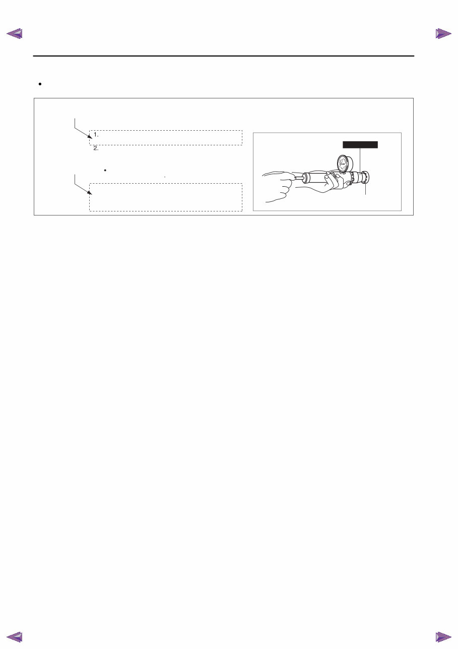
Inspection and adjustment procedures are divided into steps. Important points regarding the location and
contents of the procedures are explained in detail and shown in the illustrations.
Attach the cooling system cap to the SST and a
radiator cap tester.
Hold the cooling system cap downward and apply
pressure gradually. Verify that the pressure is held
stable for 10 s.
If the pressure is not held stable, replace the
cooling system cap.
Cooling system cap valve opening pressure
93.2—122.6 kPa {0.951—1.250 kgf/cm
2
,
13.6—17.7 psi}
COOLING SYSTEM CAP INSPECTION [MZR-CD 2.2]
COOLING SYSTEM CAP
49 9200 147
SHOWS PROCEDURE
ORDER FOR SERVICE
SHOWS
SPECIFICATION
am5ezw0000364
TO MODEL INDEX
BACK TO CHAPTER INDEX MAZDA CX5 WORKSHOP REPAIR MANUAL
GENERAL INFORMATION
00-00–7
00
Repair procedure
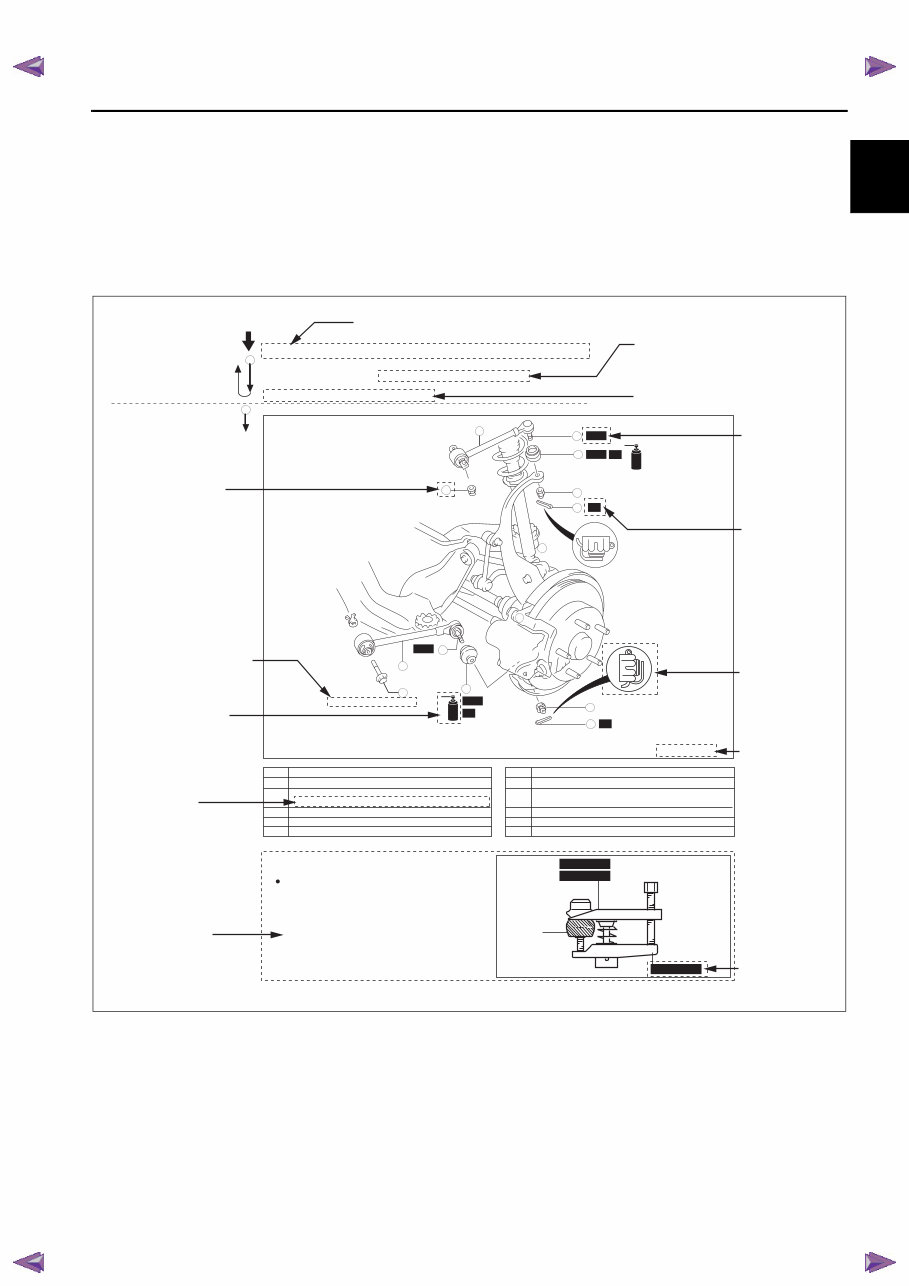
1. Most repair operations begin with an overview illustration. It identifies the components, shows how the parts fit
together, and describes visual part inspection. However, only removal/installation procedures that need to be
performed methodically have written instructions.
2. Expendable parts, tightening torques, and symbols for oil, grease, and sealant are shown in the overview
illustration. In addition, symbols indicating parts requiring the use of special service tools or equivalent are also
shown.
3. Procedure steps are numbered and the part that is the main point of that procedure is shown in the illustration
with the corresponding number. Occasionally, there are important points or additional information concerning a
procedure. Refer to this information when servicing the related part.
SST
SST
SST
SST
R
R
R
R
9
1
2
8
7
12
10
11
GREASE GREASE
4
5
3
6
GREASE GREASE
LOWER TRAILING LINK, UPPER TRAILING LINK REMOVAL/INSTALLATION
1. Jack up the rear of the vehicle and support it with safety stands.
2. Remove the undercover. (See 01-10-4 Undercover Removal)
3. Remove in the order indicated in the table.
4. Install in the reverse order of removal.
5. Inspect the rear wheel alignment and adjust it if necessary.
10
11
N·m {kgf·m, ft·lbf}
118—156 {12.0—16.0, 87—115}
94—116 {9.5—11.9, 69—86}
43—56 {4.3—5.8, 32—41}
44—60 {4.4—6.2, 32—44}
KNUCKLE
UPPER TRAILING LINK
LOWER TRAILING LINK
Split pin
Nut
Lower trailing link ball joint
(See 02-14-5 Lower Trailing Link Ball Joint Removal Note)
Bolt
Lower trailing link
Dust boot (lower trailing link)
Split pin
Nut
Upper trailing link ball joint
(See 02-14-5 Upper Trailing Link Ball Joint Removal Note)
Nut
Upper trailing link
Dust boot (upper trailing link)
Remove the ball joint using the SSTs.
1
2
3
4
5
6
7
8
9
10
11
12
Lower Trailing Link Ball Joint, Upper Trailing Link
Ball Joint Removal Note
49 T028 304
49 T028 305
49 T028 303
Procedure
SHOWS
TIGHTENING
TORQUE
UNITS
SHOWS
DETAILS
SHOWS
EXPENDABLE
PARTS
SHOWS
APPLICATION
POINTS OF
GREASE, ETC.
SHOWS
SPECIAL
SERVICE TOOL
(SST) FOR
SERVICE
OPERATION
SHOWS SERVICE ITEM (S)
INDICATES RELEVANT
REFERENCES THAT NEED
TO BE FOLLOWED
DURING INSTALLATION
2
1
"Removal/Installation"
Portion
"Inspection After
Installation" Portion
INSTALL THE PARTS BY
PERFORMING STEPS
1—3 IN REVERSE ORDER
SHOWS
TIGHTENING
TORQUE
SPECIFICATIONS
SHOWS
PROCEDURE
ORDER FOR
SERVICE
SHOWS
REFERRAL
NOTES FOR
SERVICE
SHOWS
REFERRAL
NOTES FOR
SERVICE
SHOWS
SPECIAL
SERVICE
TOOL (SST)
NO.
am5ezw0000364
TO MODEL INDEX
BACK TO CHAPTER INDEX MAZDA CX5 WORKSHOP REPAIR MANUAL
00-00–8
GENERAL INFORMATION
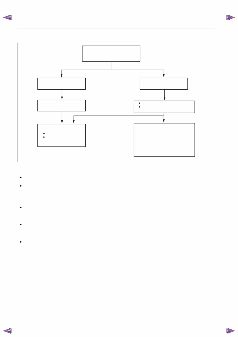
Troubleshooting Procedure
Basic flow of troubleshooting
DTC troubleshooting flow (on-board diagnostic)
Diagnostic trouble codes (DTCs) are important hints for repairing malfunctions that are difficult to simulate.
Perform the specific DTC diagnostic inspection to quickly and accurately diagnose the malfunction.
The on-board diagnostic function is used during inspection. When a DTC is shown specifying the cause of a
malfunction, continue the diagnostic inspection according to the items indicated by the on-board diagnostic
function.
Diagnostic index
The diagnostic index lists the symptoms of specific malfunctions. Select the symptoms related or most closely
relating to the malfunction.
Quick diagnosis chart (If mentioned)
The quick diagnosis chart lists diagnosis and inspection procedures to be performed specifically relating to the
cause of the malfunction.
Symptom troubleshooting
Symptom troubleshooting quickly determines the location of the malfunction according to symptom type.
CUSTOMER ARRIVES
DTC TABLE
DTC
CHECK DTC
WITHOUT DTC
1. DIAGNOSTIC INDEX
2. QUICK DIAGNOSIS CHART
(IF MENTIONED)
3. SYMPTOM
TROUBLESHOOTING
*: INDICATOR LIGHTS AND WARNING
LIGHTS THAT INDICATE MALFUNCTIONS
DTC
TROUBLESHOOTING
FLOW
WARNING LIGHT*
ON/FLASHING
CHECK FOR
PRIORITIZED DTC
NO WARNING LIGHT*
WITH SYMPTOM
IGNITION ON TEST, IDLING
TEST
DIAGNOSE BY DTC
DIAGNOSE BY SYMPTOM
(SYMPTOM TROUBLESHOOTING)
(ON-BOARD DIAGNOSTIC)
am5ezw0000364
TO MODEL INDEX
BACK TO CHAPTER INDEX MAZDA CX5 WORKSHOP REPAIR MANUAL
You're Reading a Preview
What's Included?
 Lifetime Access
Fast Download Speeds
Offline Viewing
Access Contents & Bookmarks
Full Search Facility
Print one or all pages of your manual
$41.99
2013-2015 Mazda CX-5 Service & Repair Manual
Viewed 73 Times Today

What's Included?
Lifetime Access
Fast Download Speeds
Offline Viewing
Access Contents & Bookmarks
Full Search Facility
Print one or all pages of your manual
$41.99

Secure transaction
What's Included?
Lifetime Access
Fast Download Speeds
Offline Viewing
Access Contents & Bookmarks
Full Search Facility
Print one or all pages of your manual
Description
2013-2015 Mazda CX-5 Service & Repair Manual
Thank you for considering this comprehensive Service Repair Workshop Manual.
This manual covers all Service & Repair Procedures necessary for professional mechanics and DIY enthusiasts.
DESCRIPTION:
- This manual provides step-by-step instructions and pictures for easy servicing and repairs, enabling significant cost savings by performing repairs independently.
- Once ed, the manual is accessible for printing or viewing on a tablet or smartphone.
MODELS COVERED:
- All Models/Engines/Trim/Transmissions Types Are Covered.
CONTENTS:
- This high-quality Service Repair Workshop Manual encompasses all repair procedures from A-Z, ensuring comprehensive coverage of every repair and service procedure.
COMPUTER REQUIREMENTS:
- This manual is compatible with All PC & MAC Computers, tablets, and mobile phones, requiring only adobe reader software, which is typically pre-installed or can be ed for free.
INSTANT DELIVERY:
- Upon payment by Visa, MasterCard, or PayPal, the manual will be instantly emailed to the address provided during checkout.
Customer Satisfaction Guaranteed.


