GENERAL INFORMATION 00-00–2 VEHICLE IDENTIFICATION NUMBER (VIN) CODE id000000600800 2014 Model Year End Of Sie VEHICLE IDENTIFICATION NUMBERS (VIN) id000000600100 2014 Model Year JM1 GJ1S3*E# 100001— JM1 GJ1S5*E# 100001— JM1 GJ1T3*E# 100001— JM1 GJ1T5*E# 100001— JM1 GJ1U3*E# 100001— JM1 GJ1U5*E# 100001— JM1 GJ1V3*E# 100001— JM1 GJ1V5*E# 100001— JM1 GJ1W3*E# 100001— JM1 GJ1W5*E# 100001— JM1 GJ1X3*E# 100001— JM1 GJ1X5*E# 100001— End Of Sie J M 1 G J 1 S 2 0 E 1 1 2 3 4 5 6 Model year Plant Serial No. Check digit Engine Body style S, T, U, V, W, X= Sedan Carline, series GJ= Mazda6 World manufacturer identification 0 to 9, X 3= 2.5 L (SKYACTIV-G 2.5, Mexico) 5= 2.5 L (SKYACTIV-G 2.5, U.S.A., Canada) 0= Hiroshima 1= Hofu E= 2014 Restraint system, Axle configuration JM1= Mazda/passenger car/USA 1= with side airbag, 2WD am6xuw0000649
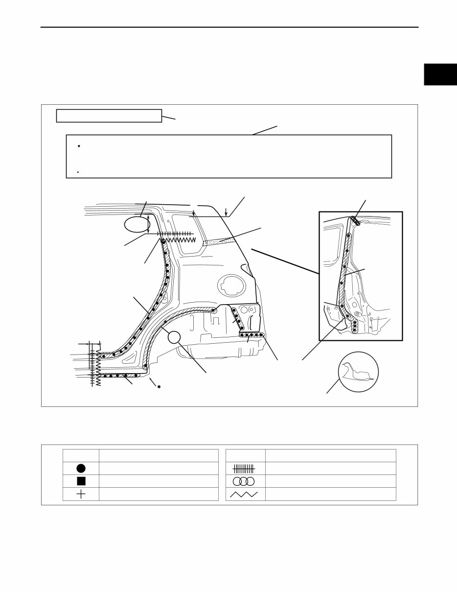
GENERAL INFORMATION 00-00–3 00-00 HOW TO USE THIS MANUAL id000000600900 Efficient Replacement of Body Panels • This section contains information on the body panels in regard to the welding types, number of spot welds, and cut-and-join locations that are necessary for panel removal and installation. • The type of weld and position are indicated by symbols. • Some sections have notes concerning the operation being performed. Thoroughly read and understand the notes before carrying out any procedures. Example Symbols of Panel Replacement • The following 6 symbols are used to indicate the type of weld that is used when replacing body panels. REAR FENDER PANEL REMOVAL Shows operation section Shows procedure, caution and note BRAZE WELDING Shows welding region Shows a cross Shows a insulator Avoid cutting with a flame as the insulator (shaded) is flammable. 1.The rear fender panel and wheel house are joined with glue at the wheel arch line. Drill the 17 weld locations indicated by (A), from the room side. Caution NOTE CUT-AND-JOINT LOCATION ROUGH CUT LOCATION Shows a dimensions {9.84in} 250mm A-A 30mm {1.18in} Shows number of weld Shows a cross location A A (A)17 17 4 5 7 1 5 acxuub00000031 SYMBOL MEANING Spot welding Arc welding (plug welding) Arc welding (spot welding) SYMBOL MEANING Continuous arc welding (Cut-and-join location) Brazing welding (oxyacetylene welding) Rough cut location ac5wzb00000204
GENERAL INFORMATION 00-00–4 Body Dimensions (Flat-plane Dimensions) • Flat-plane dimensions are the dimensions measured by projecting certain reference points onto a plane surface. • When there are no specific indications, the standard points and dimensions are symmetrical in regard to the center of the vehicle. • The hypothetical lines may differ according to the vehicle model. • The schematic diagram shows the vehicle as it is projected from the underbody. 810 {31.89} FLAT-PLANE DIMENSIONS FRONT FENDER INSTALLATION NUT acxuub00000033
GENERAL INFORMATION 00-00–5 00-00 Example Shows vehicle section When there are no specific indications, all of units are in millimeters (mm). Shows outline drawing Shows dimension The dimensions on the left and right in regard to the center of the vehicle are different. Shows hypothetical standard line Shows point symbol Point symbol Designation Hole diameter or bolt or nut size mm {in} Crossmember No,1 standard hole Front side frame standard hole Front suspension mounting block surface hole center Front suspension mounting bolt Front frame rear standard hole Front frame rear standard hole Rear side frame standard hole Link bracket Rear suspension housing A B C D E F G H I J K Rear side frame standard hole Rear side frame standard hole Shows bolt size Shows hole diameter Shows slot mm {in} UNDERBODY FLAT-PLANE DIMENSIONS φ 16 {0.62} φ 16 {0.62} φ 16 {0.62} M14 {0.55} φ 80 {3.14} Point symbol Designation Hole diameter or bolt or nut size mm {in} φ 16 {0.62} φ 31 {1.22} φ 12 {0.47} Rear suspension housing L φ 12 {0.47} φ 16 {0.62} φ 18 {0.62} 17 × 29.5 {0.66×1.16} A B C D E F G H I J K L 1,016 {40.00} 687 {27.05} 420 182 93 144 120 {7.17} {3.66} {5.67} {4.72} 1,030 140 760 68 {5.51} {2.68} 379 {16.54} {40.55} {29.92} {14.92} {25.75} 654 1,084 {42.84} 579 {22.80} 479 {18.86} 436 436 {17.17} {17.17} 445 512 660 1,043 666 {17.52} {20.16} {25.98} {41.06} {26.22} 1,106 {43.54} 1,164 543 485 484 {21.37} {19.05} 478 1,073 {37.91} 455 {17.91} 469 {18.46} 760 605 650 650 {29.92} {23.82} {25.59} {25.59} 650 {45.83} {25.59} LH RH ac9uub00000034
GENERAL INFORMATION 00-00–6 Body Dimensions (Straight-line Dimensions) • Straight-line dimensions are the actual dimensions between two standard points. • When there are no specific indications, the standard points and dimensions are symmetrical in regard to the center of the vehicle. 817 FRONT FENDER INSTALLATION NUT STRAIGHT-LINE DIMENSIONS {32.17} acxuub00000035
GENERAL INFORMATION 00-00–7 00-00 Example Symbols of Body Dimensions • The following 8 symbols are used to indicate the standard points. End Of Sie 1,128 {44.41} A B C H D I E F G 1,398 {55.04} 1,406 {55.35} {42.01} 1,067 799 {31.46} 1,263 {49.72} 1,048 {41.26} {33.50} A F G B H I C D E,E' Fr Fr Fr Fr Fr Fr Fr Fr Fr Front pillar inner designation Front pillar inner designation Front floor pan designation Adjuster installation hole Trim installation hole Harness installation hole Chaker bracket installation hole Chaker bracket installation hole A B C D E F G H I φ 16 {0.62} φ 18 {0.71} φ 16 {0.62} Harness installation hole Point symbol Designation Hole diameter or bolt or nut size mm {in} Point symbol Designation Hole diameter or bolt or nut size mm {in} Shows bolt size Shows hole diameter Shows slot 851 φ 16 {0.62} M14 {0.55} φ 31 {1.22} φ 17 {0.67} 17 × 29.5 {0.66×1.16} φ 12 {0.47} ROOM STRAIGHT-LINE DIMENSIONS (1) Shows vehicle section Shows dimension location Shows outline drawing Shows point symbol Shows point indication Without apostrophe:RH With apostrophe:LH Shows details of the standard point location Shows position and shape of the points Shows dimension No indication are shown within the outline drawing. When there are no specific indications, all of units are in millimeters (mm). mm {in} am3uub0000007 SYMBOL MEANING SYMBOL MEANING Center of circular hole Center elliptical hole Notch Panel seam, bead, etc. Bolt tip (arrow only) Center of rectangular-shaped hole Edge of rectangular-shaped hole acxuub00000037
GENERAL INFORMATION 00-00–8 AIR BAG SYSTEM SERVICE WARNINGS id000000920000 Air Bag Module Inspection • Inspecting an air bag module using a tester can operate (deploy) the air bag module, which may cause serious injury. Do not use a tester to inspect an air bag module. Always use the on-board diagnostic function to diagnose the air bag module for malfunctions. Air Bag Module Handling • Before removing the air bag module or disconnecting the air bag module connector, always switch the ignition off, disconnect the negative battery cable, and then wait for 1 min or more to allow the backup power supply of the SAS control module to deplete its stored power. • Handling a live (undeployed) air bag module that is pointed toward your body could result in serious injury if the air bag module were to accidentally operate (deploy). When carrying a live (undeployed) air bag module, point the deployment surface away from your body to lessen the chance of injury in case it operates (deploys). • A live (undeployed) air bag module placed with its deployment surface to the ground is dangerous. If the air bag module were to accidentally operate (deploy), it could cause serious injury. Always place a live (undeployed) air bag module with its deployment surface up. Side Air Bag Module Handling • Before removing the side air bag module or disconnecting the side air bag module connector, always switch the ignition off, disconnect the negative battery cable, and then wait for 1 min or more to allow the backup power supply of the SAS control module to deplete its stored power. • When a side air bag module operates (deploys) due to a collision, the interior of the seat back (pad, frame, trim) may become damaged. If a side air bag does not operate (deploy) normally from a seat back that has been reused, a serious accident may result. After a side air bag has operated (deployed), always replace both the side air bag module and the seat back (pad, frame, trim) with new parts. After servicing, verify that the seat operates normally and that the wiring harness is not caught. NO GOOD am6xuw0000606 GOOD NO GOOD am6xuw0000606 NO GOOD GOOD am6xuw0000606
This is a comprehensive factory service repair manual for the 2014-2015 Mazda 6 (Mazda6) Station Wagon. The manual features easy-to-read text sections with high-quality diagrams and instructions, making it ideal for both do-it-yourself enthusiasts and experienced mechanics. It provides step-by-step procedures and detailed exploded pictures to help you complete repairs correctly and efficiently.
The manual covers every detail of the 2014-2015 Mazda 6 (Mazda6) Station Wagon. It includes service, maintenance, and troubleshooting information for all models, engines, trims, and transmission types. This top-quality workshop repair manual is complete and intact, matching the version used in local service and repair shops to ensure full functionality and time-saving repairs.
Immediate access to the manual is available with no waiting or shipping fees, allowing repairs to begin instantly. The manual is provided in PDF format and is printable without restrictions. It is available in English and requires Adobe Reader for viewing. Payment via PayPal or credit card provides instant access to the download link upon confirmation of your purchase.
PRODUCT DETAILS:
2014-2015 Mazda 6 (Mazda6) Station Wagon
File Format: PDF
Language: English
Printable: Without any restriction
Delivery: Link will appear on the checkout page after payment is complete
Requirements: Adobe Reader
Click on the instant payment button to pay with PayPal or credit card and receive the download link instantly.
Recently Viewed
5,521,897Happy Clients
2,594,462eManuals
1,120,453Trusted Sellers
15Years in Business
Price:
Actual Price:
2014-2015 Mazda 6 Station Wagon Service & Repair Manual