GENERAL INFORMATION 00-00–2 VEHICLE IDENTIFICATION NUMBER (VIN) CODE id000000600800 2014 Model Year End Of Sie VEHICLE IDENTIFICATION NUMBERS (VIN) id000000600100 2014 Model Year JM1 GJ1S3*E# 100001— JM1 GJ1S5*E# 100001— JM1 GJ1T3*E# 100001— JM1 GJ1T5*E# 100001— JM1 GJ1U3*E# 100001— JM1 GJ1U5*E# 100001— JM1 GJ1V3*E# 100001— JM1 GJ1V5*E# 100001— JM1 GJ1W3*E# 100001— JM1 GJ1W5*E# 100001— JM1 GJ1X3*E# 100001— JM1 GJ1X5*E# 100001— End Of Sie J M 1 G J 1 S 2 0 E 1 1 2 3 4 5 6 Model year Plant Serial No. Check digit Engine Body style S, T, U, V, W, X= Sedan Carline, series GJ= Mazda6 World manufacturer identification 0 to 9, X 3= 2.5 L (SKYACTIV-G 2.5, Mexico) 5= 2.5 L (SKYACTIV-G 2.5, U.S.A., Canada) 0= Hiroshima 1= Hofu E= 2014 Restraint system, Axle configuration JM1= Mazda/passenger car/USA 1= with side airbag, 2WD am6xuw0000649
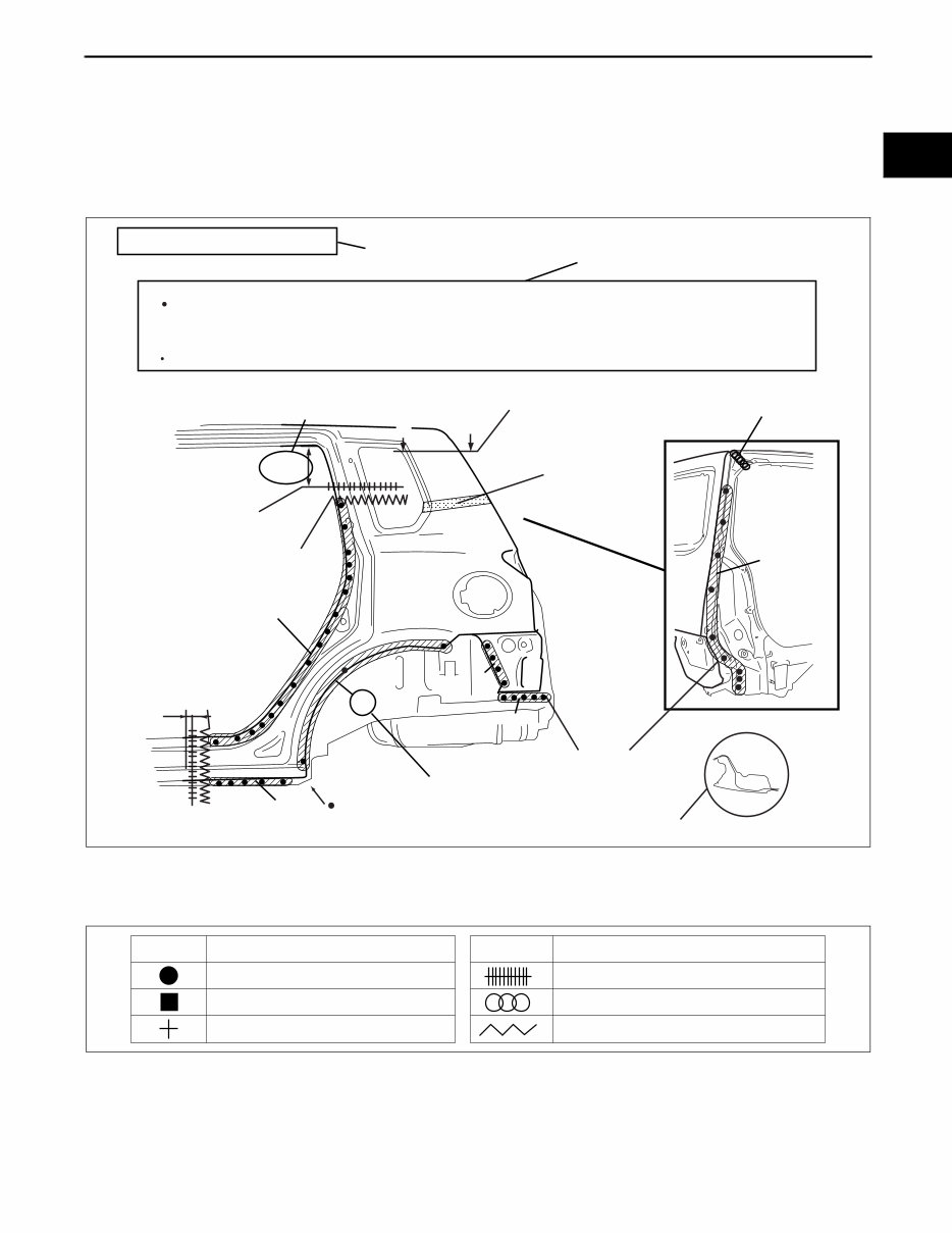
GENERAL INFORMATION 00-00–3 00-00 HOW TO USE THIS MANUAL id000000600900 Efficient Replacement of Body Panels • This section contains information on the body panels in regard to the welding types, number of spot welds, and cut-and-join locations that are necessary for panel removal and installation. • The type of weld and position are indicated by symbols. • Some sections have notes concerning the operation being performed. Thoroughly read and understand the notes before carrying out any procedures. Example Symbols of Panel Replacement • The following 6 symbols are used to indicate the type of weld that is used when replacing body panels. REAR FENDER PANEL REMOVAL Shows operation section Shows procedure, caution and note BRAZE WELDING Shows welding region Shows a cross Shows a insulator Avoid cutting with a flame as the insulator (shaded) is flammable. 1.The rear fender panel and wheel house are joined with glue at the wheel arch line. Drill the 17 weld locations indicated by (A), from the room side. Caution NOTE CUT-AND-JOINT LOCATION ROUGH CUT LOCATION Shows a dimensions {9.84in} 250mm A-A 30mm {1.18in} Shows number of weld Shows a cross location A A (A)17 17 4 5 7 1 5 acxuub00000031 SYMBOL MEANING Spot welding Arc welding (plug welding) Arc welding (spot welding) SYMBOL MEANING Continuous arc welding (Cut-and-join location) Brazing welding (oxyacetylene welding) Rough cut location ac5wzb00000204
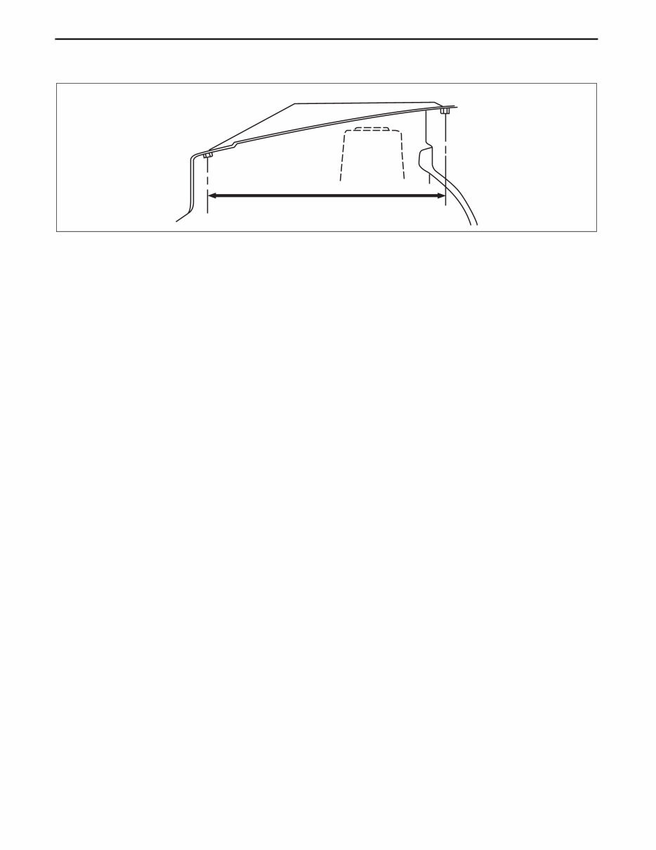
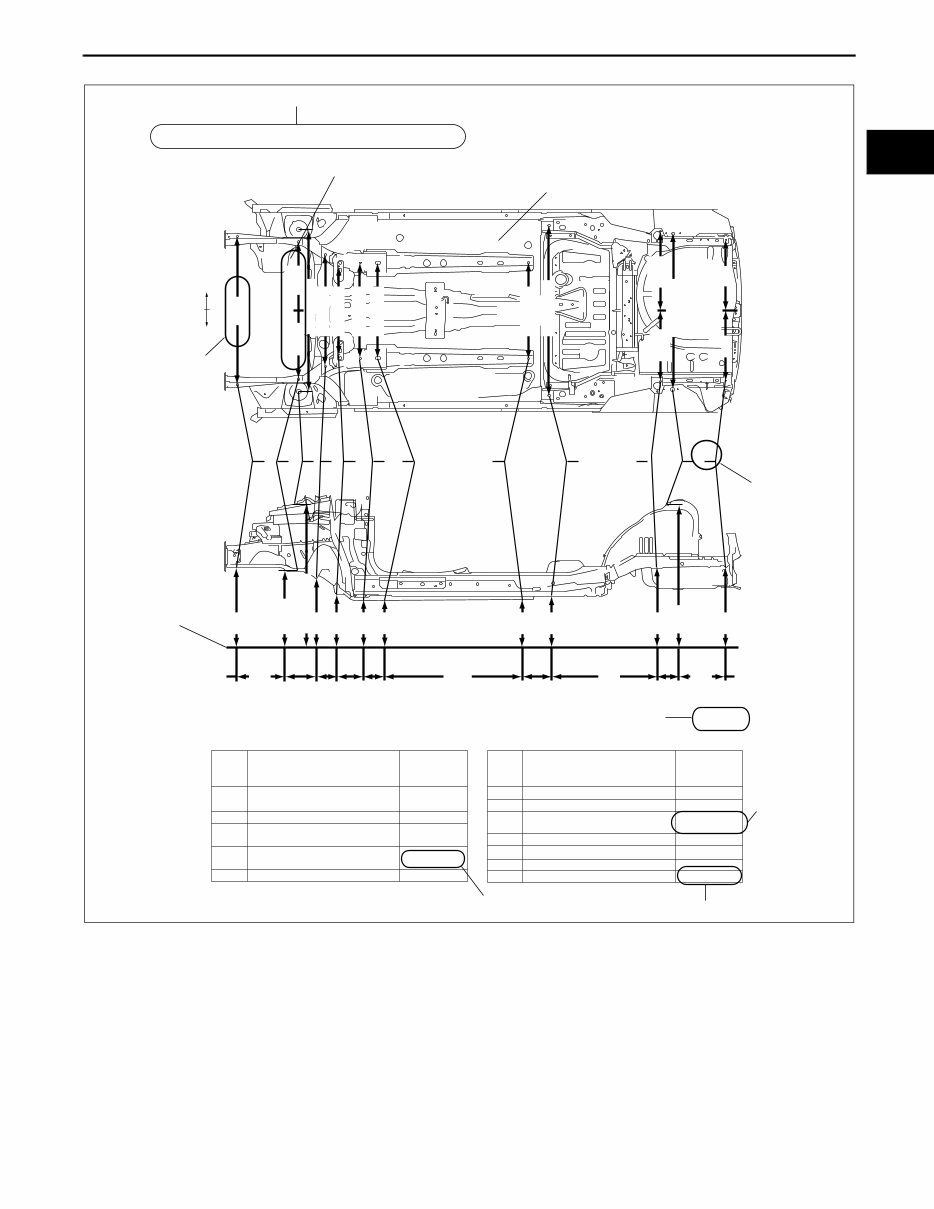
GENERAL INFORMATION 00-00–4 Body Dimensions (Flat-plane Dimensions) • Flat-plane dimensions are the dimensions measured by projecting certain reference points onto a plane surface. • When there are no specific indications, the standard points and dimensions are symmetrical in regard to the center of the vehicle. • The hypothetical lines may differ according to the vehicle model. • The schematic diagram shows the vehicle as it is projected from the underbody. 810 {31.89} FLAT-PLANE DIMENSIONS FRONT FENDER INSTALLATION NUT acxuub00000033
GENERAL INFORMATION 00-00–5 00-00 Example Shows vehicle section When there are no specific indications, all of units are in millimeters (mm). Shows outline drawing Shows dimension The dimensions on the left and right in regard to the center of the vehicle are different. Shows hypothetical standard line Shows point symbol Point symbol Designation Hole diameter or bolt or nut size mm {in} Crossmember No,1 standard hole Front side frame standard hole Front suspension mounting block surface hole center Front suspension mounting bolt Front frame rear standard hole Front frame rear standard hole Rear side frame standard hole Link bracket Rear suspension housing A B C D E F G H I J K Rear side frame standard hole Rear side frame standard hole Shows bolt size Shows hole diameter Shows slot mm {in} UNDERBODY FLAT-PLANE DIMENSIONS φ 16 {0.62} φ 16 {0.62} φ 16 {0.62} M14 {0.55} φ 80 {3.14} Point symbol Designation Hole diameter or bolt or nut size mm {in} φ 16 {0.62} φ 31 {1.22} φ 12 {0.47} Rear suspension housing L φ 12 {0.47} φ 16 {0.62} φ 18 {0.62} 17 × 29.5 {0.66×1.16} A B C D E F G H I J K L 1,016 {40.00} 687 {27.05} 420 182 93 144 120 {7.17} {3.66} {5.67} {4.72} 1,030 140 760 68 {5.51} {2.68} 379 {16.54} {40.55} {29.92} {14.92} {25.75} 654 1,084 {42.84} 579 {22.80} 479 {18.86} 436 436 {17.17} {17.17} 445 512 660 1,043 666 {17.52} {20.16} {25.98} {41.06} {26.22} 1,106 {43.54} 1,164 543 485 484 {21.37} {19.05} 478 1,073 {37.91} 455 {17.91} 469 {18.46} 760 605 650 650 {29.92} {23.82} {25.59} {25.59} 650 {45.83} {25.59} LH RH ac9uub00000034
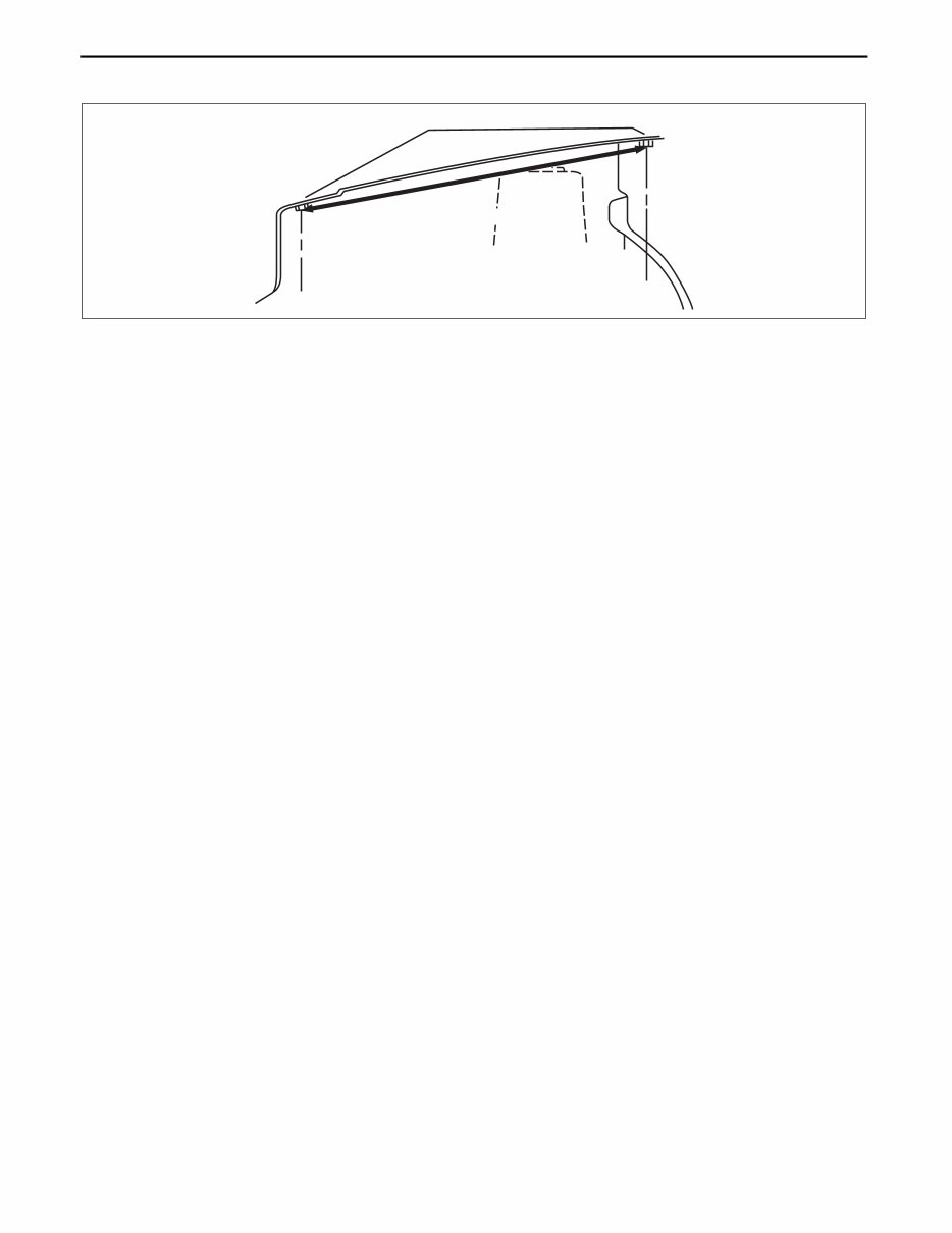
GENERAL INFORMATION 00-00–6 Body Dimensions (Straight-line Dimensions) • Straight-line dimensions are the actual dimensions between two standard points. • When there are no specific indications, the standard points and dimensions are symmetrical in regard to the center of the vehicle. 817 FRONT FENDER INSTALLATION NUT STRAIGHT-LINE DIMENSIONS {32.17} acxuub00000035
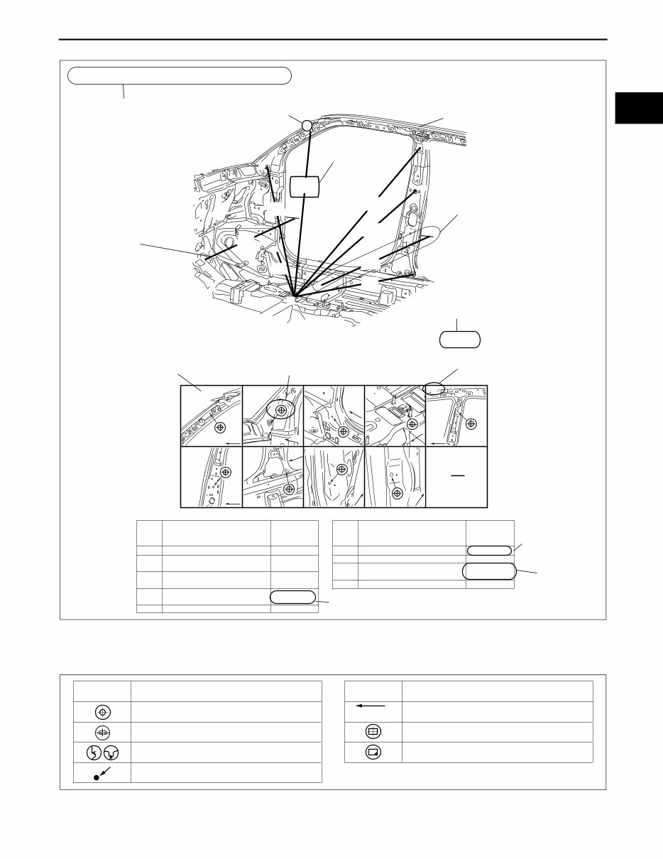
GENERAL INFORMATION 00-00–7 00-00 Example Symbols of Body Dimensions • The following 8 symbols are used to indicate the standard points. End Of Sie 1,128 {44.41} A B C H D I E F G 1,398 {55.04} 1,406 {55.35} {42.01} 1,067 799 {31.46} 1,263 {49.72} 1,048 {41.26} {33.50} A F G B H I C D E,E' Fr Fr Fr Fr Fr Fr Fr Fr Fr Front pillar inner designation Front pillar inner designation Front floor pan designation Adjuster installation hole Trim installation hole Harness installation hole Chaker bracket installation hole Chaker bracket installation hole A B C D E F G H I φ 16 {0.62} φ 18 {0.71} φ 16 {0.62} Harness installation hole Point symbol Designation Hole diameter or bolt or nut size mm {in} Point symbol Designation Hole diameter or bolt or nut size mm {in} Shows bolt size Shows hole diameter Shows slot 851 φ 16 {0.62} M14 {0.55} φ 31 {1.22} φ 17 {0.67} 17 × 29.5 {0.66×1.16} φ 12 {0.47} ROOM STRAIGHT-LINE DIMENSIONS (1) Shows vehicle section Shows dimension location Shows outline drawing Shows point symbol Shows point indication Without apostrophe:RH With apostrophe:LH Shows details of the standard point location Shows position and shape of the points Shows dimension No indication are shown within the outline drawing. When there are no specific indications, all of units are in millimeters (mm). mm {in} am3uub0000007 SYMBOL MEANING SYMBOL MEANING Center of circular hole Center elliptical hole Notch Panel seam, bead, etc. Bolt tip (arrow only) Center of rectangular-shaped hole Edge of rectangular-shaped hole acxuub00000037
GENERAL INFORMATION 00-00–8 AIR BAG SYSTEM SERVICE WARNINGS id000000920000 Air Bag Module Inspection • Inspecting an air bag module using a tester can operate (deploy) the air bag module, which may cause serious injury. Do not use a tester to inspect an air bag module. Always use the on-board diagnostic function to diagnose the air bag module for malfunctions. Air Bag Module Handling • Before removing the air bag module or disconnecting the air bag module connector, always switch the ignition off, disconnect the negative battery cable, and then wait for 1 min or more to allow the backup power supply of the SAS control module to deplete its stored power. • Handling a live (undeployed) air bag module that is pointed toward your body could result in serious injury if the air bag module were to accidentally operate (deploy). When carrying a live (undeployed) air bag module, point the deployment surface away from your body to lessen the chance of injury in case it operates (deploys). • A live (undeployed) air bag module placed with its deployment surface to the ground is dangerous. If the air bag module were to accidentally operate (deploy), it could cause serious injury. Always place a live (undeployed) air bag module with its deployment surface up. Side Air Bag Module Handling • Before removing the side air bag module or disconnecting the side air bag module connector, always switch the ignition off, disconnect the negative battery cable, and then wait for 1 min or more to allow the backup power supply of the SAS control module to deplete its stored power. • When a side air bag module operates (deploys) due to a collision, the interior of the seat back (pad, frame, trim) may become damaged. If a side air bag does not operate (deploy) normally from a seat back that has been reused, a serious accident may result. After a side air bag has operated (deployed), always replace both the side air bag module and the seat back (pad, frame, trim) with new parts. After servicing, verify that the seat operates normally and that the wiring harness is not caught. NO GOOD am6xuw0000606 GOOD NO GOOD am6xuw0000606 NO GOOD GOOD am6xuw0000606
This manual contains maintenance and repair procedures for the MAZDA 6 2014.
The service manual has been prepared as an aid to improve the quality of repairs by giving the serviceman an accurate understanding of the product and showing him the correct way to perform repairs and make judgments.
Make sure you understand the contents of this manual and use it to full defect at every opportunity. This service manual mainly contents the necessary technical information for operation performed in a service workshop.
This Service and Repair Manual Covers the following Models:
MAZDA 6 2014 Workshop Service Repair Manual
This service manual is specifically written for the do-it-yourselfer as well as the experienced mechanic. Using this repair manual is an inexpensive way to keep your vehicle working properly. Each manual provides step-by-step instructions based on the complete disassembly of the machine. It is this level of detail, along with hundreds of photos and illustrations, that guide the reader through each service and repair procedure. Simply print out the pages you need or print the entire manual as a whole!!!
MAZDA 6 2014 Workshop Service Repair Manual:
Detailed substeps expand on repair procedure information.
Numbered instructions guide you through every repair procedure step by step.
Bold figure number help you quickly match illustrations with instructions.
Detailed illustrations, drawings and photos guide you through every procedure.
Enlarged inset helps you identify and examine parts in detail.
Numbered table of contents is easy to use so that you can find the information you need fast.
After your payment, you will have instant access to your access! No shipping fee, no waiting on postal delivery, you can start doing your repairs right away!
PRODUCT DETAILS:
File Format:
Language: English
Specifications: Full Printable
Zoom IN/OUT: YES
Delivery: !!
Requirements: Adobe Reader & Win
Compatible: All Versions of Windows & Mac
MAZDA 6 2014 Service Repair Manual. with illustrations, wiring diagram and photos in format.
A Small Example Of The Type Of Info That MAZDA 6 2014 Workshop Service Repair Manual Covers:
MAZDA 6 2014 Gearbox & Clutch
MAZDA 6 2014 Electric Starter
MAZDA 6 2014 Crankshaft/Transmission/Balancer
MAZDA 6 2014 Wheels & Tyres
MAZDA 6 2014 Electrical System
MAZDA 6 2014 Braking System
MAZDA 6 2014 Suspension
MAZDA 6 2014 Periodic checks & Adjustments
MAZDA 6 2014 Wiring Diagrams
MAZDA 6 2014 Engine Lubrication and Cooling
MAZDA 6 2014 Ignition System
MAZDA 6 2014 Transmission System
MAZDA 6 2014 Troubleshooting
MAZDA 6 2014 Lubrication System
MAZDA 6 2014 Rear Wheel System
MAZDA 6 2014 Cylinder Head/Valves
MAZDA 6 2014 Cooling system
MAZDA 6 2014 Engine Removal and Installation
MAZDA 6 2014 General Information
MAZDA 6 2014 Battery/Charging System
MAZDA 6 2014 Chassis
MAZDA 6 2014 Technical Information & Specifications
MAZDA 6 2014 Lights/Meters/Switches
MAZDA 6 2014 Frame/Body Panels/Exhaust System
MAZDA 6 2014 Maintenance
MAZDA 6 2014 Alternator/Starter Clutch
MAZDA 6 2014 Fenders and Exhaust Pipe
MAZDA 6 2014 Front Wheel and Steering System
MAZDA 6 2014 Specifications
MAZDA 6 2014 Engine Fuel System
MAZDA 6 2014 Crankcase/Piston/Cylinder
MAZDA 6 2014 Engine Combustion System
MAZDA 6 2014 Fuel injection system
MAZDA 6 2014 Body & Fixtures Abundant Illustrations, Lots of pictures & diagrams, Plus Lots More !!