

2014-2015 Mazda6 Service & Repair Manual
What's Included?
Fast Download Speeds
Offline Viewing
Access Contents & Bookmarks
Full Search Facility
Print one or all pages of your manual
Title Section
GENERAL INFORMATION 00
BODY
STRUCTURE
CONSTRUCTION 80A
PANEL REPLACEMENT 80B
WATER-PROOF AND RUST
PREVENTIVE
80C
DIMENSIONS 80D
PLASTIC BODY PARTS 80E
CONSTRUCTION
STANDARD VALVES
80F
CONTENTS
2014-present
Bodyshop
Manual
FOREWORD
This bodyshop manual is intended for
use by technicians of Authorized Mazda
Dealers to help them service and repair
Mazda vehicles. It can also be useful to
owners and operators of Mazda vehicles in
performing limited repair and maintenance
on Mazda vehicles.
For proper repair and maintenance, a
thorough familiarization with this manual is
important, and it should always be kept in a
handy place for quick and easy reference.
All the contents of this manual, including
drawings and specifications, are the latest
available at the time of printing.
As modifications affecting repair or
maintenance occur, relevant information
supplementary to this volume will be made
available at Mazda dealers. This manual
should be kept up-to-date.
Mazda Motor Corporation reserves the
right to alter the specifications and contents
of this manual without obligation or ad-
vance notice.
All rights reserved. No part of this book may
be reproduced or used in any form or
by any means, electronic or mechanical
including photocopying and recording and
the use of any kind of information storage
and retrieval system-without permission in
writing.
Mazda Motor Corporation
HIROSHIMA, JAPAN
APPLICATION:
This manual is applicable to vehicles beginning
with the Vehicle Identification Numbers (VIN),
shown on the following page.
© 2012 Mazda Motor Corporation
PRINTED IN U.S.A., DECEMBER 2012
Form No. 3525–1U–12L
Part No. 9999–95–099F–14

VEHICLE IDENTIFICATION NUMBERS (VIN)
JM1 GJ1S3*E# 100001—
JM1 GJ1S5*E# 100001—
JM1 GJ1T3*E# 100001—
JM1 GJ1T5*E# 100001—
JM1 GJ1U3*E# 100001—
JM1 GJ1U5*E# 100001—
JM1 GJ1V3*E# 100001—
JM1 GJ1V5*E# 100001—
JM1 GJ1W3*E# 100001—
JM1 GJ1W5*E# 100001—
JM1 GJ1X3*E# 100001—
JM1 GJ1X5*E# 100001—

00
GENERAL INFORMATION
00-00–1
SECTION
00-00
Toc of SCT
GENERAL INFORMATION . . . . 00-00
Toc of SCT
00-00 GENERAL INFORMATION
VEHICLE IDENTIFICATION
NUMBER (VIN) CODE . . . . . . . . . . . . . . 00-00–2
VEHICLE IDENTIFICATION NUMBERS
(VIN) . . . . . . . . . . . . . . . . . . . . . . . . . . . . 00-00–2
2014 Model Year . . . . . . . . . . . . . . . . . . 00-00–2
HOW TO USE THIS MANUAL . . . . . . . . . 00-00–3
Efficient Replacement of
Body Panels . . . . . . . . . . . . . . . . . . . . 00-00–3
Symbols of Panel Replacement . . . . . . 00-00–3
Body Dimensions (Flat-plane
Dimensions) . . . . . . . . . . . . . . . . . . . . 00-00–4
Body Dimensions (Straight-line
Dimensions) . . . . . . . . . . . . . . . . . . . . 00-00–6
Symbols of Body Dimensions . . . . . . . . 00-00–7
AIR BAG SYSTEM
SERVICE WARNINGS . . . . . . . . . . . . . . 00-00–8
Air Bag Module Inspection . . . . . . . . . . 00-00–8
Air Bag Module Handling . . . . . . . . . . . 00-00–8
Side Air Bag Module Handling . . . . . . . 00-00–8
SAS Control Module Handling . . . . . . . 00-00–9
Crash Zone Sensor Handling . . . . . . . . 00-00–9
Side Air Bag Sensor Handling. . . . . . . . 00-00–9
Pre-tensioner Seat Belt Inspection . . . . 00-00–10
SERVICE PRECAUTIONS . . . . . . . . . . . . 00-00–10
Arrangement of Workshop . . . . . . . . . . 00-00–10
Safety Precautions . . . . . . . . . . . . . . . . 00-00–10
Vehicle Protection . . . . . . . . . . . . . . . . . 00-00–10
Remove Dangerous Articles . . . . . . . . . 00-00–10
Use of Pulling Equipment . . . . . . . . . . . 00-00–11
Prevent Short Circuits . . . . . . . . . . . . . . 00-00–11
EFFICIENT REMOVAL OF
BODY PANELS . . . . . . . . . . . . . . . . . . . . 00-00–12
Body Measurements . . . . . . . . . . . . . . . 00-00–12
Prevention of Body Deformation. . . . . . 00-00–12
Selection of Cut-and-join Locations . . . 00-00–12
Removal of Associated Parts . . . . . . . . 00-00–12
Rough Cutting of Damaged Panel . . . . 00-00–13
EFFICIENT INSTALLATION OF
BODY PANELS . . . . . . . . . . . . . . . . . . . 00-00–13
Checking Preweld Measurements And
Watching . . . . . . . . . . . . . . . . . . . . . . 00-00–13
Welding Notes . . . . . . . . . . . . . . . . . . . 00-00–13
Spot Welding Notes . . . . . . . . . . . . . . . 00-00–14
Checking Weld Strength. . . . . . . . . . . . 00-00–15
INSTALLATION PREPARATIONS. . . . . . 00-00–16
Rough Cutting of New Parts . . . . . . . . . 00-00–16
Determination of Welding Method . . . . 00-00–16
Making Holes for Arc Welding . . . . . . . 00-00–16
Application of Weld-through Primer . . . 00-00–17
ANTICORROSION,
SOUND INSULATION,
AND VIBRATION INSULATION . . . . . . 00-00–17
Body Sealing . . . . . . . . . . . . . . . . . . . . 00-00–17
Application of Undercoating . . . . . . . . . 00-00–17
Application of Rust Inhibitor . . . . . . . . . 00-00–18
Application of Dumping Sheet . . . . . . . 00-00–18
ABBREVIATION . . . . . . . . . . . . . . . . . . . 00-00–18
IDENTIFICATION NUMBER
LOCATIONS . . . . . . . . . . . . . . . . . . . . . 00-00–19
Vehicle Identification Number (VIN) . . . 00-00–19
Engine Type/Number . . . . . . . . . . . . . . 00-00–19
BODY COLORS . . . . . . . . . . . . . . . . . . . . 00-00–19
Color Code and Color Name . . . . . . . . 00-00–19
Verification of Primary Color Mixture for
Body Color . . . . . . . . . . . . . . . . . . . . . 00-00–19
End of Toc
BM: GENERAL INFORMATION
GENERAL INFORMATION
00-00–2
VEHICLE IDENTIFICATION NUMBER (VIN) CODE
id000000600800
2014 Model Year
End Of Sie
VEHICLE IDENTIFICATION NUMBERS (VIN)
id000000600100
2014 Model Year
JM1 GJ1S3*E# 100001—
JM1 GJ1S5*E# 100001—
JM1 GJ1T3*E# 100001—
JM1 GJ1T5*E# 100001—
JM1 GJ1U3*E# 100001—
JM1 GJ1U5*E# 100001—
JM1 GJ1V3*E# 100001—
JM1 GJ1V5*E# 100001—
JM1 GJ1W3*E# 100001—
JM1 GJ1W5*E# 100001—
JM1 GJ1X3*E# 100001—
JM1 GJ1X5*E# 100001—
End Of Sie
J M 1 G J 1 S 2 0 E 1 1 2 3 4 5 6
Model year
Plant
Serial No.
Check digit
Engine
Body style S, T, U, V, W, X= Sedan
Carline, series GJ= Mazda6
World manufacturer identification
0 to 9, X
3= 2.5 L (SKYACTIV-G 2.5, Mexico)
5= 2.5 L (SKYACTIV-G 2.5, U.S.A., Canada)
0= Hiroshima
1= Hofu
E= 2014
Restraint system, Axle configuration
JM1= Mazda/passenger car/USA
1= with side airbag, 2WD
am6xuw0000649
GENERAL INFORMATION
00-00–3
00-00
HOW TO USE THIS MANUAL
id000000600900
Efficient Replacement of Body Panels
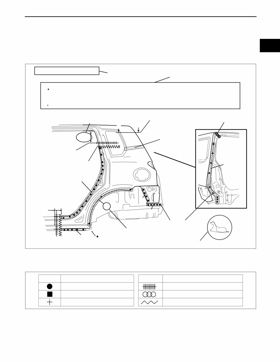
• This section contains information on the body panels in regard to the welding types, number of spot welds, and
cut-and-join locations that are necessary for panel removal and installation.
• The type of weld and position are indicated by symbols.
• Some sections have notes concerning the operation being performed. Thoroughly read and understand the
notes before carrying out any procedures.
Example
Symbols of Panel Replacement
• The following 6 symbols are used to indicate the type of weld that is used when replacing body panels.
REAR FENDER PANEL REMOVAL
Shows operation section
Shows procedure, caution and note
BRAZE WELDING
Shows welding region
Shows a cross
Shows a insulator
Avoid cutting with a flame as the insulator (shaded) is flammable.
1.The rear fender panel and wheel house are joined with glue at the wheel arch line.
Drill the 17 weld locations indicated by (A), from the room side.
Caution
NOTE
CUT-AND-JOINT LOCATION
ROUGH CUT LOCATION
Shows a dimensions
{9.84in}
250mm
A-A
30mm
{1.18in}
Shows number of weld
Shows a cross location
A A
(A)17
17
4
5
7 1
5
acxuub00000031
SYMBOL MEANING
Spot welding
Arc welding (plug welding)
Arc welding (spot welding)
SYMBOL MEANING
Continuous arc welding (Cut-and-join location)
Brazing welding (oxyacetylene welding)
Rough cut location
ac5wzb00000204
You're Reading a Preview
What's Included?
Fast Download Speeds
Offline Viewing
Access Contents & Bookmarks
Full Search Facility
Print one or all pages of your manual
$39.99
$51.99
Viewed 56 Times Today


Secure transaction
What's Included?
Fast Download Speeds
Offline Viewing
Access Contents & Bookmarks
Full Search Facility
Print one or all pages of your manual
$39.99
$51.99
Get the 2014-2015 Mazda6 Service & Repair Manual for comprehensive factory service, repairs, and troubleshooting procedures. This professional manual is essential for both professional mechanics and DIY enthusiasts. It includes detailed photos, diagrams, and step-by-step instructions for completing every job correctly.
- Print any page or the entire manual as needed.
- Use the manual on multiple computers without limitations.
- This is the full manual with no trial periods or expiration, usable for life.
- Fully compatible with Windows and MAC computers.
Click the button to access this invaluable resource instantly on your computer, tablet, or smartphone.


